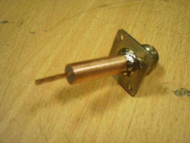
Announcement

Collapse
No announcement yet.

Who performs the first longitudinal Moon-Bounce in history?

Collapse
X
 
  • Filter
  • Time
  • Show
Clear All
new posts

  • #16
    Greetings,

    The problem with moonbounce is validating the actual path taken by
    the signal. You could imagine ionosphere reflections, intermediate
    ionized gas clouds, repeater satellites, Dark Knight repeaters, and
    plain old fraud invalidating the exercise.

    For what it is worth, AstroEngineer.wordpress.com claims that
    Mars rovers (Spirit, etc) are equipped with working superluminal
    transmitters. (Checkout the gnomon on the color calibrator
    as a candidate for the spherical transmitter.) His claim is that
    timestamped data at JPL documents pre-arrival of the data stream
    from the superluminal path, as compared to the conventional path.

    I think the more convincing prospect for demonstrating superluminal
    longitudinal waves is to redo Wheatstone's demonstration.
    Comment


    • #17
      Originally posted by broli View Post
      I'm not knowledgeable in that field.

      But what would the difference be between one large surface and many small individual patches covered over a large surface. The boundaries of these small patches do not connect but all are connected to the center of the sphere. Wouldn't that eliminate the standing wave issue on the sphere?
      As far as I can tell, there is no problem once you get a standing wave in your sphere. The idea of using a sphere with a normal transmitter comes from the paper I posted earlier:

      http://bit.ly/sKQUok

      A spherical surface with a uniform periodic changing net charge q is equivalent to a pulsating point charge density.

      [...]

      The ball antenna source. –
      The geometry of the spherical antenna is indicated in fig. 1. A 433.59 MHz signal is fed into the inside of the metal sphere through a coaxial cable, where the outside grounded conductor acts as a shield. The result is an oscillating uniform spherical charge density that is the source of the radiating longitudinal electric E field. Mathematically a spherically symmetric source can generate only scalar waves; so the ball antenna can only generate a Φ-wave, and, thus, only a longitudinal electrodynamic E-wave. The spherically symmetric current density J within the ball, that gives rise to the pulsating surface charge source, is divergenceless, ∇ · J = 0; so ∇ · A = 0 and ∇ × A = 0; and no transverse wave can arise. The ball antenna as a receiver detects the net charge induced by the component of the incident E field normal to the front surface; so only longitudinal E-waves can be detected. An absorbing screen can be introduced to determine the direction of the incident longitudinal wave. Stray transverse fields generated by leads and neighboring objects play only a minor role.
      So, when you feed your sphere from the centre, no matter what, the waves always end up with the same phase at the outside. So, you can work with a small sphere when feeding from the centre without any standing wave problems. When fed from the centre, the problems are mostly related to how much power you can effectively radiate with such an antenna.

      When not fed from the centre, it depends on how small your sphere is compared to the wavelenghts used wether or not you get too much unwanted phase differences across the surface of your sphere. If it is small enough, you won't have a problem with that respect, but you won't be able to radiate much power either. And a small sphere fed from the center also won't radiate much power.

      Now normally an antenna is designed to resonate in order to get the largest possible radiation. So, I figured: the sphere must also resonate if you want to be able to transmit power effectively. And it turned out that the sphere the guys in the paper used had a radius of about 1/4 lambda.

      But feeding a sphere from the centre is very complicated. How do you fix a feedline to the centre of a shpere?

      Now when the sphere is designed to resonate at the frequency you desire, you will get a standing wave pattern such that the waves at the surface of your ball are always in phase because of the geometry of the sphere. And then and only then you can feed your sphere from the outside without any problem as far as I can tell, while still being able to radiate the optimum amount of power.

      So, from a practical point of view it is much easier to do it like that...
      Last edited by lamare; 11-06-2011, 06:37 PM. Reason: expanded quote

      Comment


      • #18
        Originally posted by KurtNalty View Post
        I think the more convincing prospect for demonstrating superluminal
        longitudinal waves is to redo Wheatstone's demonstration.
        Yes that is a great idea, with todays equipment, as you said, so it reduces their ability as much as possible to speciously counter argue the matter, as there most likely will be interests that would prefer it is never known that will grab for any straw they can to derail the experiment.

        Comment


        • #19
          @lamare

          doesnt the sphere become part of the whole system, which is to say, the best power transfer through the system that could be hoped for would be an exact impedance match between the coil capacitor and the environment at the system level operating frequency? It appears it would be dependent on the physical dimensions of the sphere as you talked about and all external factors, height, nearby objects etc etc? either way it would also need the transmitter to properly load up as well. I am having difficulty imagining how someone can get all these factors knowing what we know about wire mass, length, size etc into a best compromise situation as a system.

          If you wanted to feed the center what about putting a small solid core ball on the end of the coax center and insulator from the braid and the coax mounted so the ball is in the center of the sphere?

          Oddly enough my now 90 year old uncle used to put a small hollow ball over the tip of all his radio antenna's including these 900 mhz phones and to my surprize the reception was noticeably better!
          Last edited by Kokomoj0; 11-06-2011, 08:36 PM.

          Comment


          • #20
            Originally posted by lamare View Post
            Jus try getting low frequency sounds, like a 100 Hz sine wave, from a loudspeaker designed for high frequencies (tweeter) or just any speaker with a very small cone and you know what I mean....

            For the moon-bounce project, we need high gain antenna's and considerable power, so we need to use sattellite dishes as antenna, fed with a sphere. Since readily available dishes have a diameter of in the order of 1 to may be 5m, I am aiming for high frequencies, at least 500 MHz or so.
            coils and design at that frequency get really hairy.

            Interestingly I am planning at some point in building a transmitter and that was the frequency of my first choice but am rethinking it due to the added complexities. For what you are trying to do I dont think you have that luxury. Lots of people still have those old 9ft sat dishes in their yards that might be a consideration.

            Comment


            • #21
              Originally posted by lamare View Post
              Posted this on the jk_wireless Yahoo group:

              Yahoo! Groups


              I realize this gets a bit confusing. What should it be now, n * 1/2 lambda or n * 1/4 lambda??

              All right. Now the outside of your sphere is per definition a voltage node. You get these every 1/2 lambda.

              If you want to drive your sphere from a normal transmitter, which is designed to feed a normal dipole or 1/4 lambda antenna at a current node, you need to feed your sphere from the centre and it needs to have a radius of n * 1/4 lambda in order to get your current node at the centre in order to keep your transmitter happy.

              If you want to drive your sphere from a transmitter capable of driving a dipole at a voltage node (basically: high voltage, low current), you can either use a sphere with a radius of n * 1/4 lamda and drive it from the outside, or you can take a sphere with a radius of n * 1/2 lambda and drive it from the centre.

              At this moment it still has to be determined how to drive an antenna at a voltage node exactly.

              Eric Dollard's experiments suggests that capacitive coupling to a normal transmitter may work. A transmitter like Tesla's TMT probably also works very well, because it's coil is in a self-resonance mode and normally you use the already "open" side of the coil to drive your sphere. So, if you match the size of your sphere to the oscillation frequency of your TMT when oscillating without any capacitive load at the top, you're probably O.K.

              Its too bad Eric did not elaborate on that. He did say he was able to tune up with good swr into the ground in that conference video I believe.

              In this case wouldnt you simply impedance match your transmitter to operate into the primary with enough tuning capability to adjust for variations reflected from the tower to maintain a decent swr?

              I presume your amp would be electrically isolated and driving the primary coil into the ground no?

              Then in a pinch couldnt you adjust your voltage or current mode by a length of coax between the sphere and the top of the coil?

              Comment


              • #22
                Good news!

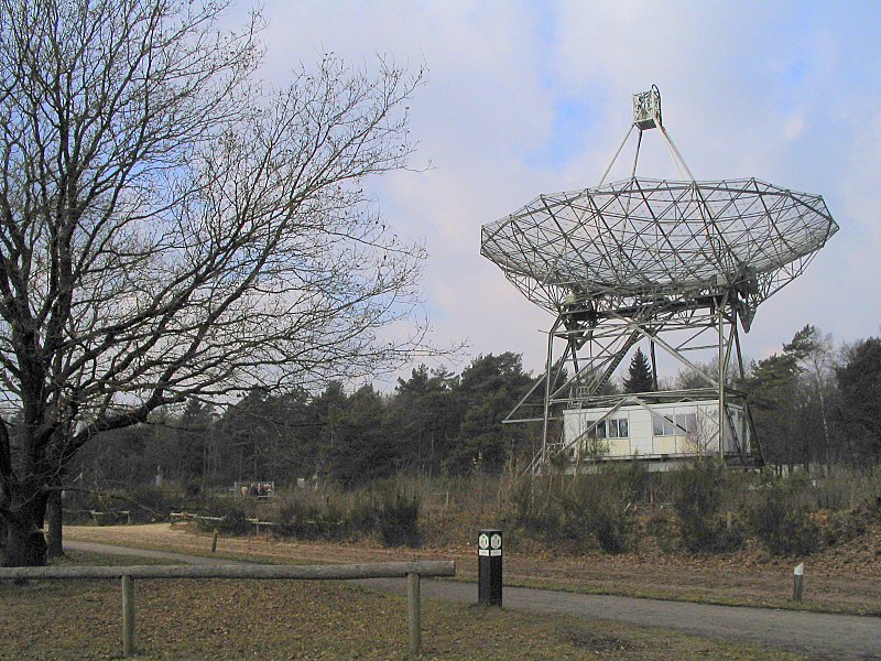
                If we manage to buld a proper transmitter, we can make use of this 25 meter dish for an experiment:
                Dwingeloo Radio Observatory - Wikipedia, the free encyclopedia


                The guy who responded to my mail is involved with the restoration of this dish and he said they could mount a feed at "their dish" and "aim a shot".

                WOW!
                Last edited by lamare; 10-31-2013, 07:52 PM. Reason: uptated url for image.

                Comment


                • #23
                  The lamare longitudinal dipole antenna (and/or dish feed)...

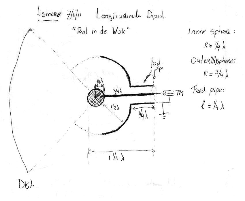
                  Yesterday evening, I have been thinking about how to design a longitudinal antenna for use with a normal transmitter. The design used in the Swiss proof-of-concept was fed from the centre, but the coax mantle was floating, which is not such a good idea. This kept bothering me and after some deep thinking, I suddenly got an idea. The lamare longitudinal dipole:


                  The idea is to make a whip antenna of 1 1/4 lambda, where at the tip of the whip we mount a sphere with a radius of 1/4 lambda. Concentric to that one, we mount a hollow sphere with a radius of 3/4 lambda.

                  So, in between the spheres you have 1/2 lambda, so both are at a voltage node with a phase difference of 180 degrees.

                  The outer sphere acts as a reflective shield. I have drawn this one as a half sphere, but of course you can match the opening in the outer sphere to the angle of your dish, and you get some gain as a result.

                  Since a normal transmitter is designed to couple into a current node, we attach a feedpipe (or how do you call this?) of 1/4 lambda to the outer sphere, which is connected to ground at the feed point.

                  The inner sphere is connected to the same feed point by means of a 3/4 lambda whip.

                  The interesting thing is that because of the difference in propagation speed of a factor pi/2, your transversal resonance frequencies are also a factor pi/2 away from the frequency for which we design our longitudinal dipole, which causes a nice suppression of all the transversal junk we don't want in this case....

                  Attached Files

                  Comment


                  • #24
                    in his work on the transmission of electricity, Dollard makes the distinction between dielectric and and magnetic induction but in this paper did not go to the elements of exactly how it works.

                    The electromagnetic theory, or what was known as the Hertzian wave theory in Tesla's era, fails to explain certain observations made in practical radio engineering. According to E.M. theory the propagating velocity of electric induction must be the velocity of light. In the practical world of engineering however, the factor π/2, or 1.57 times the velocity of light will appear in wave calculations. Is it not coincidental that Tesla claimed that the effective propagation velocity of his wireless system was π/2 faster than the so-called speed of light?

                    Also, according to E.M. theory, the propagation of electric induction must be the cross combination of the dielectric induction and the magnetic induction, these two inductions never propagating independently. The work of J.J. Thomson and M. Faraday indicate that these two distinct forms of induction do propagate independently. Wheatstone claimed that the dielectric induction propagated at π/2 times faster than light.

                    Does anyone have any further information of the exact process that takes place that creates the pi/2 c condition?

                    Comment


                    • #25
                      Originally posted by Kokomoj0 View Post
                      in his work on the transmission of electricity, Dollard makes the distinction between dielectric and and magnetic induction but in this paper did not go to the elements of exactly how it works.

                      Does anyone have any further information of the exact process that takes place that creates the pi/2 c condition?
                      In essence, it's a matter of rotational movement of the ether in the case of the magnetic component versus straight movement in the case of the dielectric component.

                      The magnetic component travels a netto path of half a circle, pi * r, while the dielectric component travels straight trough the centre of the circle, 2 * r. The division of these renders pi/2. In other words: the path the magnetic component has to travel is pi/2 times as long as the path the dielectric component has to travel. The magnetic component takes a detour, while the dielectric component does not....
                      Last edited by lamare; 11-07-2011, 06:22 PM. Reason: typo

                      Comment


                      • #26
                        Originally posted by lamare View Post
                        Yesterday evening, I have been thinking about how to design a longitudinal antenna for use with a normal transmitter. The design used in the Swiss proof-of-concept was fed from the centre, but the coax mantle was floating, which is not such a good idea. This kept bothering me and after some deep thinking, I suddenly got an idea. The lamare longitudinal dipole:

                        The idea is to make a whip antenna of 1 1/4 lambda, where at the tip of the whip we mount a sphere with a radius of 1/4 lambda. Concentric to that one, we mount a hollow sphere with a radius of 3/4 lambda.

                        So, in between the spheres you have 1/2 lambda, so both are at a voltage node with a phase difference of 180 degrees.

                        The outer sphere acts as a reflective shield. I have drawn this one as a half sphere, but of course you can match the opening in the outer sphere to the angle of your dish, and you get some gain as a result.

                        Since a normal transmitter is designed to couple into a current node, we attach a feedpipe (or how do you call this?) of 1/4 lambda to the outer sphere, which is connected to ground at the feed point.

                        The inner sphere is connected to the same feed point by means of a 3/4 lambda whip.

                        The interesting thing is that because of the difference in propagation speed of a factor pi/2, your transversal resonance frequencies are also a factor pi/2 away from the frequency for which we design our longitudinal dipole, which causes a nice suppression of all the transversal junk we don't want in this case....


                        @lamare

                        nice concept and design.

                        you will be able to fine tune it with the pipe I presume.

                        2 questions....

                        What kind of voltage do you predict on the node?

                        and how do you plan to switch it from the transmission mode to receiver mode?

                        Comment


                        • #27
                          Originally posted by Kokomoj0 View Post
                          @lamare

                          nice concept and design.

                          you will be able to fine tune it with the pipe I presume.

                          2 questions....

                          What kind of voltage do you predict on the node?

                          and how do you plan to switch it from the transmission mode to receiver mode?
                          I have no idea at this moment how to calculate voltages on the antenna. Have to figure that out. It is an interesting question, though.

                          In principle the antenna design works exactly the same as a normal whip antenna of 1 1/4 lambda from the transmitter / feedline's point of view. The only difference is the geometry which is designed to generate longitudinal dielectric waves instead of transversal waves. The antenna should work both as a transmitter and as a receiver antenna equally well.

                          And since with a moonbounce we have a return time of about 1.6 seconds, we can transmit a signal for about 1 second after which we have "plenty" of time (about 0.9 seconds) to release the TX button and receive the signal bouncing of the moon trough the same antenna and tranceiver. So, for the actual experiment we only need one antenna and one transceiver, which is very nice, because those 25 meter dishes do not come in large quantities.

                          At the moment, I am investigating the possibilities to realize an antenna for the 1296 radio amateur frequency which is "reserved" for moon-bouncing activities. Since in The Netherlands there are no ERP rules and a maximum of 120 Watt output power is allowed for 1296 MHz, we can kick some a** with this 25 meter dish, that's for sure.

                          However, I still have to arrange a powerfull 1296 MHz transceiver, but first things first. Before we can do anything, we have to build ourselves an antenna....

                          The dimensions I calculated for 1296 MHz:

                          lambda: 1.57 * 300/1296 = 471/1296 = 36,36 cm.

                          3/4 lambda: 27,27 cm.
                          Diameter "wok" - the big one - : 54,54 cm.

                          1/4 lambda: 9,09 cm.
                          Diameter "bol in de wok" - the small one: 18,18 cm.

                          Length feed pipe (balun): 9,09 cm.


                          I would love to have some idea about what kind of error margins are acceptable. The Swiss proof-of-concept suggests an error margin of up to 10% can be acceptable, but this kind of a challenging operation, so I guess we would have to stay within 1 cm of error for the spheres.

                          For the construction of the large sphere, I am currently looking at the possibilities of realizing a design similar to this:

                          Radio Astronomy Telescope Project


                          So, the idea is to make some kind of support structure with ribs and use some kind of mesh to make the reflective sphere.

                          Probably these can be constructed using flexible copper tubes. Then we would make a couple of rings and parts in the shape of half rings and solder these together to make a support structure.
                          Last edited by lamare; 11-07-2011, 09:23 PM.

                          Comment


                          • #28
                            Arend , I met a guy from the USA who is replicating tesla/ Meyls magnifying transmitter sets for a 3rd of the price with 1 watt transmission, (now upscaling to 500watt.) He is selling the 1w sets with alu ball antenna's for 300usd, meyl charges 800 euro or so.

                            He gets 1.2 times C on a resonating frequencies somewhere between 4-8 Mhz.
                            He verified that the scalar resonant frequency is related to length of wire in the coil, and speed of light times 1.2
                            He also noticed the overunity effect at the receiver but so far hasnt explained me in detail about it.

                            I have my doubts regarding the Meyl sets like you and this german set out Meyls errors: Skalarwellen.

                            This is just a remark regarding the earlier posts in this topic.
                            Tesla's 1.54 factor (12HZ from tesla / 7.8Hz schumann resonance)
                            is close to pi/2 but these 2 values seem to be mixed up in many stories I read.

                            Im also from holland
                            Last edited by kitcar; 11-07-2011, 11:07 PM.

                            Comment


                            • #29
                              Small scale proof of concept for antenna with WiFi.

                              I just realized that when people want to experiment with this antenna design, it could easily be scaled down for the 2.4 GHz band, so you can use a wifi device, such as a linksys Linux router, for a proof of concept for longitudinal communication.

                              Since the dimensions for that are much smaller, construction of an antenna is much easier to do. And if your only aim is to experiment with this over a short distance, you don't have to worry too much about error margins.

                              The ideal dimensions for a 2.4 GHz antenna would be:

                              Lambda : 19,33 cm.
                              Diameter large sphere: 29,00 cm.
                              Diameter small sphere: 9,67 cm.
                              Length feed pipe: 4,83 cm.
                              Length whip: 14,50 cm.

                              Here is some more information on a DIY WiFi antenna:
                              Homebrew 2.4 GHz 14 dBi Wide Angle Sector antenna

                              With a detail on how to construct the feedline, which is called a balun:

                              Have fun!

                              Last edited by lamare; 11-07-2011, 10:52 PM. Reason: oops. radius should be diameter

                              Comment


                              • #30
                                Originally posted by lamare View Post
                                I have no idea at this moment how to calculate voltages on the antenna. Have to figure that out. It is an interesting question, though.

                                [CENTER]
                                I would think that the you would be able to at least get the near the rail voltage for unmoduated rf, but wouldnt you have to match it then drive the ball dierctly at such a high frequency? The nice thing is that it would be very directional but may require some kind of tracking to keep it on target too... This can get quite involved real quick. UNfortunately I have very little expereince with super high freq microwave baluns.

                                Is that your back yard?

                                Lambda : 19,33 cm.
                                Diameter large sphere: 29,00 cm.
                                Diameter small sphere: 9,67 cm.
                                Length feed pipe: 4,83 cm.
                                Length whip: 14,50 cm.
                                If you are using a solid sphere wouldnt you stil need to account for the propagation velocity of the ball and transmitting elements?

                                Also on a side note, I believe tesla said that there is no energy in matter and that matter gets all its energy from the environment. In what respect did he mean that? Is he looking at energy as power output or power that can be extracted? I mentioned that to a friend yesterday and the reply was that there is energy in matter such as wood can burn etc and I realized that tesla must have had some very specific set of circumstances he was referring to. Yet if it proves einstein wrong then you would think it applies to al matter generally. If you are up on that one too, I have not found how tesla was applying that?
                                Last edited by Kokomoj0; 11-08-2011, 03:34 AM.

                                Comment

                                Working...
                                X