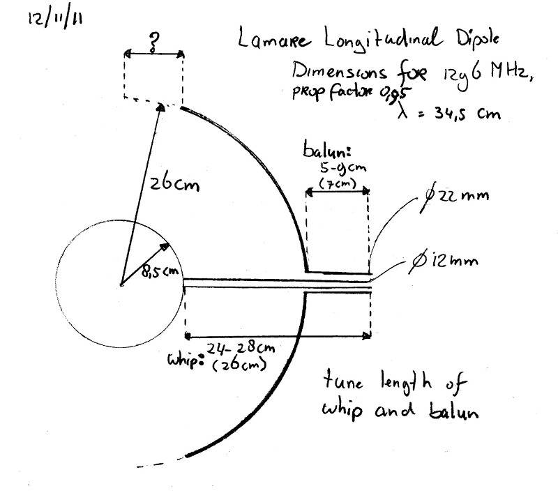
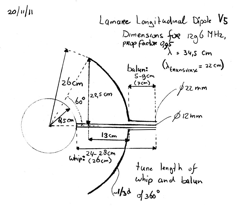
To Lamare Longitudinal Wave
Possiblly using other Bands for which we may have RF exciters.
622.062 = Television = 1.4811 x C Upper Sideband unwanted but suppressed by SWR
420.000 = Ham = 1.4811 x C = F0 Longitudinal Wave Transverse Wave
283.573 = Military = 1.4811 x C Lower Sideband unwanted but suppressed by SWR
===============================
333.041 = Military = 1.4811 x C Upper Sideband unwanted but suppressed by SWR
224.860 = Ham = F0 or Center of Oscillation by standard C Transcerse Wave
151.820 = MURS = 1.4811 x C Lower Sideband to tune to; unwanted but suppressed by SWR
If one were to tune to best SWR for 151.820 this most likely would support the Longitudinal wave as a primary and sidebands as follows:
224.860 = Ham = 1.4811 x C Upper Sideband unwanted Transverse Wave but suppressed by SWR
151.820 = MURS = 1.4811 x C = F0 Longitudinal Wave
102.504 = Broadcast = 1.4811 x C Lower Sideband unwanted Transverse Wave but suppressed by SWR
Also you may want to think about a coil at the feed point of the open end that is fed from the feed point by wire that causes the magnetic current to flow in the opposite direction to cancel some of the magnetic current.
This may however cancel the Longitudinal wave since the two would be out of phase. However if a resistor is placed in line with the coil then a partial decrease in the magnetic current may be achieved without full cancellation of the Longitudinal wave.
You may have to make the feed a bifilar pancake coil.
Another option is to place a primary coil around the can at F0 and then wind a secondary coil around that in the reverse direction Tesla coil style. This may be tried with the standard feed point that you have but not energized, hence it becomes a passive tuning fork style radiator ala a sound style transverse wave from a speaker.
Another option is to use your standard feed point but connected to a bifilar wound pancake coil, for magnetic current canceling. Also you may want to try placing a small ball at the top of your feed point instead of the disk.
Just some ideas I have been toying with myself. You are almost there so I hope some of this may help.
Dave


Comment