Eric Dollard is quoted in an interview with Thomas Brown, speaking of the Farnsworth Multipactor as a free energy device; "Yes, probably the only real free energy device that anyone ever demonstrated which can be reproduced."
An article on the Borderlands website offers anecdotal evidence that Farnsworth operated a multipactor oscillator as a transmitter with a 25 watt input and a 25 watt output.
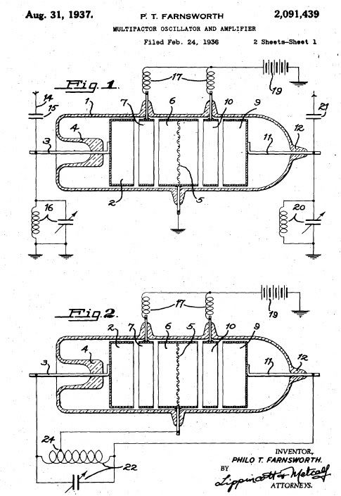
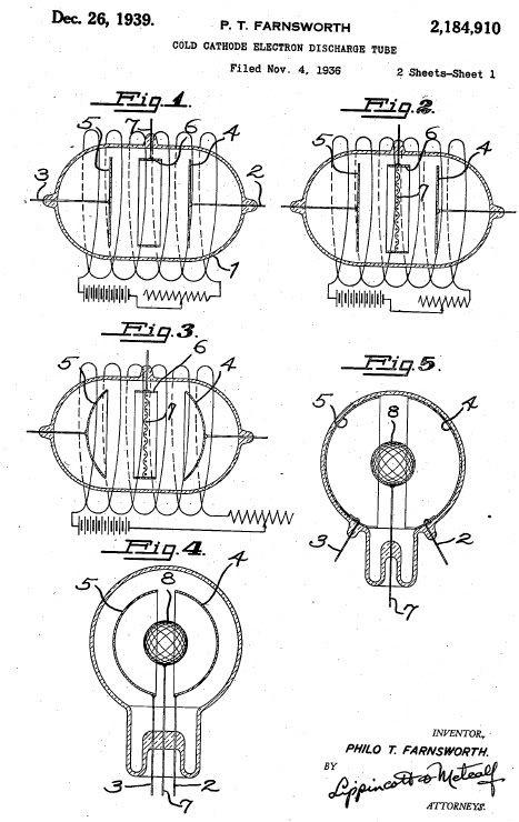
More information about the Multipactor can also be found in an article about the Farnsworth Fusor and of course in the Farnsworth patents themselves.

multipactor by OrionLightShip
After extensive studying of Farnsworth's patents, and without empirical evidence; I cannot arbitrarily agree with the 25 in and 25 out statement. It is possible however, that he improved his designs enough that it is, in fact, true. I believe it to be so, because I believe that I have found what he knew. Note that with the same power input and output, it becomes possible to daisy chain an infinite number of tubes and with extremely hot cathodes (~ 1000 C ) the implications and advantage becomes obvious if the cathodes extend out of the sealed tube with a fluted heat sink as is done on high power vacuum tubes in order to cool the plate.
Farnsworth's documents and lab notes are archived at a university in Utah, however, the university web site states that some material may be restricted due to State or Federal laws. One would immediately surmise that National Security might be the reason for such restrictions, yet I don't believe the powers that be would allow material left in documents of this importance to reside in a university library, so one is left to draw their own conclusions as to why these restrictions might apply to Farnsworth or if in fact they even apply specifically to his archive.
Multipactors utilize cathode coatings ( ~5 microns ) that emit multiple secondary electrons upon impact of one primary electron. Even pure metals such as nickel, silver, gold will work but modern high temperature secondary emitting materials use a cermet (ceramic metal) high temperature material such as 80% magnesium oxide and 20% gold, silver, or nickel co-sputtered onto the main cathode body. The secondary electrons come from the cathode's and coating's free electron source, and must be replaced as energy is withdrawn from a load.
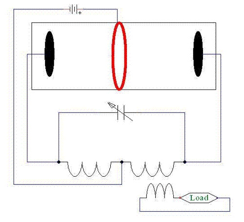
The secondary electrons have little energy when they come off the cathode surface and must be accelerated to the other side of the tube. Farnsworth used a high voltage (hundreds) on the anode to accelerate the electrons from one side of the tube to the other. Some electrons become out of phase and never aquire enough velocity to strike the opposing cathode. They make several trips back and forth past the anode giving up their electrostatic energy to the cathodes and resonant tank circuit and slow down until they are collected on the anode. The power supply then must do work to re-insert electrons back into the circuit via a center tapped inductor in the tank circuit.
Losses at the anode constitute almost all of the losses encountered in this device and Farnsworth's later iterations provided for interrupting the anode current ( pulsing ) which increased efficiency on the order of a full magnitude. It became so efficient that it was necessary to either de-tune the tank circuit or to pull energy out of the curcuit by imposing a load as shown in the circuit diagram I have provided. Failure to compensate for the increased efficiency would lead to a run away condition that would destroy the tube in short order.
The reason for the improved efficiency is quite obvious. The anode acts first to accelerate the electron and then acts to slow it down after passing through the anode on the way to the other cathode. This creates a situation whereby many electrons never strike the cathode and end up "dying" and being collected by the anode instead of multiplying. By pulsing the anode at the proper interval and with the proper duty cycle, the anode current losses can be significantly reduced but not eliminated as many electrons, due to phase relationships caused by time of emission and coloumb repulsion in the electron cloud will still "get lost" and do not make the trip with the proper timing to the other cathode.
The solution is, of course to eliminate the anode and it's inherent losses and replace it with a device that accelerates the electrons from one side to the other without ever imposing a "slow down" condition. More electrons can make the full trip and multiply and therefore more energy is available to the load. Another feature in my design (not shown) force the "slow" electrons back onto the cathodes for reuse. Provision must be made for injecting electrons back into the cathode free electron supply to fulfill all circuit requirements. Can you tell me what that looks like?
Hint: No magnet required or desired.
Provisions have been made with two attorneys and four familly members that if I should die for any reason, copies of my notebook will be made available to a long list of people involved in the free energy research realm, including this and other forums as well. Faxes will fly!
My success or failure will be published here for two reasons. I don't want others to try and duplicate something that doesn't work, the likes of which you see on youtube. If successful it will be used to free humanity. If I ever make a dime off this, it will only occur as a result of building devices for those incapable of doing it themselves. Greed on this planet must come to an end and we must become sovereign and self-sufficient and not reliant upon the failed concept of industrialized agriculture and a government that no longer tolerates peaceful demonstrations or healthy food production. Community values and food growing co-ops are our future. Money and corruption must become our past.
Argentina anyone? Wish me luck.
Orion
An article on the Borderlands website offers anecdotal evidence that Farnsworth operated a multipactor oscillator as a transmitter with a 25 watt input and a 25 watt output.
More information about the Multipactor can also be found in an article about the Farnsworth Fusor and of course in the Farnsworth patents themselves.

multipactor by OrionLightShip
After extensive studying of Farnsworth's patents, and without empirical evidence; I cannot arbitrarily agree with the 25 in and 25 out statement. It is possible however, that he improved his designs enough that it is, in fact, true. I believe it to be so, because I believe that I have found what he knew. Note that with the same power input and output, it becomes possible to daisy chain an infinite number of tubes and with extremely hot cathodes (~ 1000 C ) the implications and advantage becomes obvious if the cathodes extend out of the sealed tube with a fluted heat sink as is done on high power vacuum tubes in order to cool the plate.
Farnsworth's documents and lab notes are archived at a university in Utah, however, the university web site states that some material may be restricted due to State or Federal laws. One would immediately surmise that National Security might be the reason for such restrictions, yet I don't believe the powers that be would allow material left in documents of this importance to reside in a university library, so one is left to draw their own conclusions as to why these restrictions might apply to Farnsworth or if in fact they even apply specifically to his archive.
Multipactors utilize cathode coatings ( ~5 microns ) that emit multiple secondary electrons upon impact of one primary electron. Even pure metals such as nickel, silver, gold will work but modern high temperature secondary emitting materials use a cermet (ceramic metal) high temperature material such as 80% magnesium oxide and 20% gold, silver, or nickel co-sputtered onto the main cathode body. The secondary electrons come from the cathode's and coating's free electron source, and must be replaced as energy is withdrawn from a load.
The secondary electrons have little energy when they come off the cathode surface and must be accelerated to the other side of the tube. Farnsworth used a high voltage (hundreds) on the anode to accelerate the electrons from one side of the tube to the other. Some electrons become out of phase and never aquire enough velocity to strike the opposing cathode. They make several trips back and forth past the anode giving up their electrostatic energy to the cathodes and resonant tank circuit and slow down until they are collected on the anode. The power supply then must do work to re-insert electrons back into the circuit via a center tapped inductor in the tank circuit.
Losses at the anode constitute almost all of the losses encountered in this device and Farnsworth's later iterations provided for interrupting the anode current ( pulsing ) which increased efficiency on the order of a full magnitude. It became so efficient that it was necessary to either de-tune the tank circuit or to pull energy out of the curcuit by imposing a load as shown in the circuit diagram I have provided. Failure to compensate for the increased efficiency would lead to a run away condition that would destroy the tube in short order.
The reason for the improved efficiency is quite obvious. The anode acts first to accelerate the electron and then acts to slow it down after passing through the anode on the way to the other cathode. This creates a situation whereby many electrons never strike the cathode and end up "dying" and being collected by the anode instead of multiplying. By pulsing the anode at the proper interval and with the proper duty cycle, the anode current losses can be significantly reduced but not eliminated as many electrons, due to phase relationships caused by time of emission and coloumb repulsion in the electron cloud will still "get lost" and do not make the trip with the proper timing to the other cathode.
The solution is, of course to eliminate the anode and it's inherent losses and replace it with a device that accelerates the electrons from one side to the other without ever imposing a "slow down" condition. More electrons can make the full trip and multiply and therefore more energy is available to the load. Another feature in my design (not shown) force the "slow" electrons back onto the cathodes for reuse. Provision must be made for injecting electrons back into the cathode free electron supply to fulfill all circuit requirements. Can you tell me what that looks like?
Hint: No magnet required or desired.
Provisions have been made with two attorneys and four familly members that if I should die for any reason, copies of my notebook will be made available to a long list of people involved in the free energy research realm, including this and other forums as well. Faxes will fly!
My success or failure will be published here for two reasons. I don't want others to try and duplicate something that doesn't work, the likes of which you see on youtube. If successful it will be used to free humanity. If I ever make a dime off this, it will only occur as a result of building devices for those incapable of doing it themselves. Greed on this planet must come to an end and we must become sovereign and self-sufficient and not reliant upon the failed concept of industrialized agriculture and a government that no longer tolerates peaceful demonstrations or healthy food production. Community values and food growing co-ops are our future. Money and corruption must become our past.
Argentina anyone? Wish me luck.

Orion


Comment