Announcement

Collapse
No announcement yet.

Eric's "Crystal Radio Initiative" Challenge

Collapse
X
 
  • Filter
  • Time
  • Show
Clear All
new posts

  • Eric's "Crystal Radio Initiative" Challenge

    I thought this challenge needs some promoting to get us all involved in it.

    I want people who are taking on this challenge to post their progress, results, questions, photos etc. in this thread.

    Basically anything that involves this challenge belongs to this thread. We can assist each other in problems, setbacks, windings etc. and generally work together in completing Eric's challenge.

    The objective would be to see how many of us can successfully complete this challenge. Hopefully it also encourages more people to experiment in this field.

    Remember, the idea of the challenge is to get us thinking and doing things on our own, so please try it yourself first, then if you hit a wall that you can't breach, post here and ask help.

    Don't give blueprints or schematics for a working system! If you manage to complete this challenge, post the date of completion here and we can compare results later in another thread specifically made for complete, tested and working setups.

    In short, get off your monitor and start experimenting!

    -Sebastian Bowles -Lost in Northern Territory

  • #2
    Some excellent advice and info by Dr. Green

    http://www.energeticforum.com/eric-d...ompendium.html

    Some very helpfull scientific data and info on coil building etc. here. Use it to your advantage and learn from it.

    Comment


    • #3
      Originally posted by Sebacid View Post
      I thought this challenge needs some promoting to get us all involved in it.

      I want people who are taking on this challenge to post their progress, results, questions, photos etc. in this thread.

      Basically anything that involves this challenge belongs to this thread. We can assist each other in problems, setbacks, windings etc. and generally work together in completing Eric's challenge.

      The objective would be to see how many of us can successfully complete this challenge. Hopefully it also encourages more people to experiment in this field.

      Remember, the idea of the challenge is to get us thinking and doing things on our own, so please try it yourself first, then if you hit a wall that you can't breach, post here and ask help.

      Don't give blueprints or schematics for a working system! If you manage to complete this challenge, post the date of completion here and we can compare results later in another thread specifically made for complete, tested and working setups.

      In short, get off your monitor and start experimenting!

      -Sebastian Bowles -Lost in Northern Territory
      Hi Sebastian,

      What specifically is this challenge and where can I read up on it?

      Best regards,

      Luther
      Electrostatic charges manipulating magneto-gravitic streams...

      Comment


      • #4
        Originally posted by LutherG View Post
        Hi Sebastian,

        What specifically is this challenge and where can I read up on it?

        Best regards,

        Luther
        Hi Luther,

        The challenge is located amidst the jungle in this forum in Eric's posts as T-Rex.

        Here is a short copy describing it:


        "The objective here is to scale the “Crystal Set”, a step at a time, into a Tesla Transformer for the reception of medium wave band, 300 – 3000 kilocycle A.M. broadcasts. No license is required for this and the broadcast station provides the power.And this objective cooperates with the primary objective. That is; Who will be the first ham to disprove Einstein’s theory? An International contest, but who will sponsor it, Iran maybe?We have the good fortune in the “Crystal Set Initiative” that, in theory at least, a quarter wave A.M. broadcast tower, and its 120 quarter wave ground radials, must emit a pair of waves as shown by Tesla in his basic diagrams.

        Hence it can be seen that a pair of waves are engendered by this transmission system. (Tower and Star Radials). One wave, Hertzian, is the over ground wave, the other wave, Telluric, is the under ground wave. These two waves arrive at the point of reception in their own distinct time frames, giving rise to a difference in phase. Hence, multiple rings of interference patterns are produced. Since the Hertzian portion, over ground, time frame is based upon the velocity of light, then the Telluric portion, under ground, time frame gives the Telluric velocity. Two crystal sets, one over ground, one under ground, and a basic oscilloscope , that simple. I have done this at Landers.Concluding, a Tesla Magnification Transformer, properly proportioned can, in theory, actually draw power from a local 50 kW station. Several hundred watts of power reception is likely. This would prove Tesla once and for all. No antenna, just a good ground, and a nice and bright 100 watt light bulb.This would overturn physics more than any billion dollar C.E.R.N. project. A ham radio operator overturns Einstein for 100 bucks. What a concept."

        Read,
        Tesla, “The True Wireless”
        Tesla, “System of Concatenated Tuned Circuits”
        Dollard, “System for the Transmission and Reception of Telluric Electric Waves”
        A.R.R.L. “Radio Amatuers Handbook”. Chapter “H.F. Transmitters, & Tank Circuits”


        Here is another link that has most of Eric's posts shortlisted:

        Eric Dollard | Gestalt Reality

        Hope this helps,

        -Seb

        Comment


        • #5
          What would this look like?

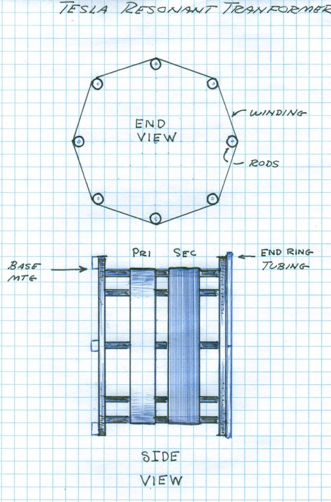
          I have looked at this and done a bit of reading at the context and I don't really have a good feeling for where to start. I am thinking perhaps I should apply some of the functions and formulae that EPD has gathered and perhaps compute the size and other parameters of the necessary coils and capacitors? If someone would suggest some specific numbers and create an example of the calculations, that would seem like a helpful starting point. First, pick a typical AM frequency, such as that of your local 50 KVA AM station, and use that as an example. It seems we need to solve a simultaneous equation. There are two values for inductors and also two? values for capacitors. Then there is the actual circuit diagram. Again, I have a picture in my mind, but I'm not sure if it is right. If you want to post you sample data, my eyes are open. Thx.
          Tesla Disruptive Discharge Transformer.jpg
          There is a reason why science has been successful and technology is widespread. Don't be afraid to do the math and apply the laws of physics.

          Comment


          • #6
            Originally posted by wayne.ct View Post
            I have looked at this and done a bit of reading at the context and I don't really have a good feeling for where to start. I am thinking perhaps I should apply some of the functions and formulae that EPD has gathered and perhaps compute the size and other parameters of the necessary coils and capacitors? If someone would suggest some specific numbers and create an example of the calculations, that would seem like a helpful starting point. First, pick a typical AM frequency, such as that of your local 50 KVA AM station, and use that as an example. It seems we need to solve a simultaneous equation. There are two values for inductors and also two? values for capacitors. Then there is the actual circuit diagram. Again, I have a picture in my mind, but I'm not sure if it is right. If you want to post you sample data, my eyes are open. Thx.
            [ATTACH]13624[/ATTACH]
            Hi Wayne,

            All the information necessary to do this can be found in this forum under Eric's posts as T-Rex. See links in my previous reply. You just have to get your hands dirty and look for the information. That is a part of the challenge, to get people doing.

            But here's some advice to get you started:

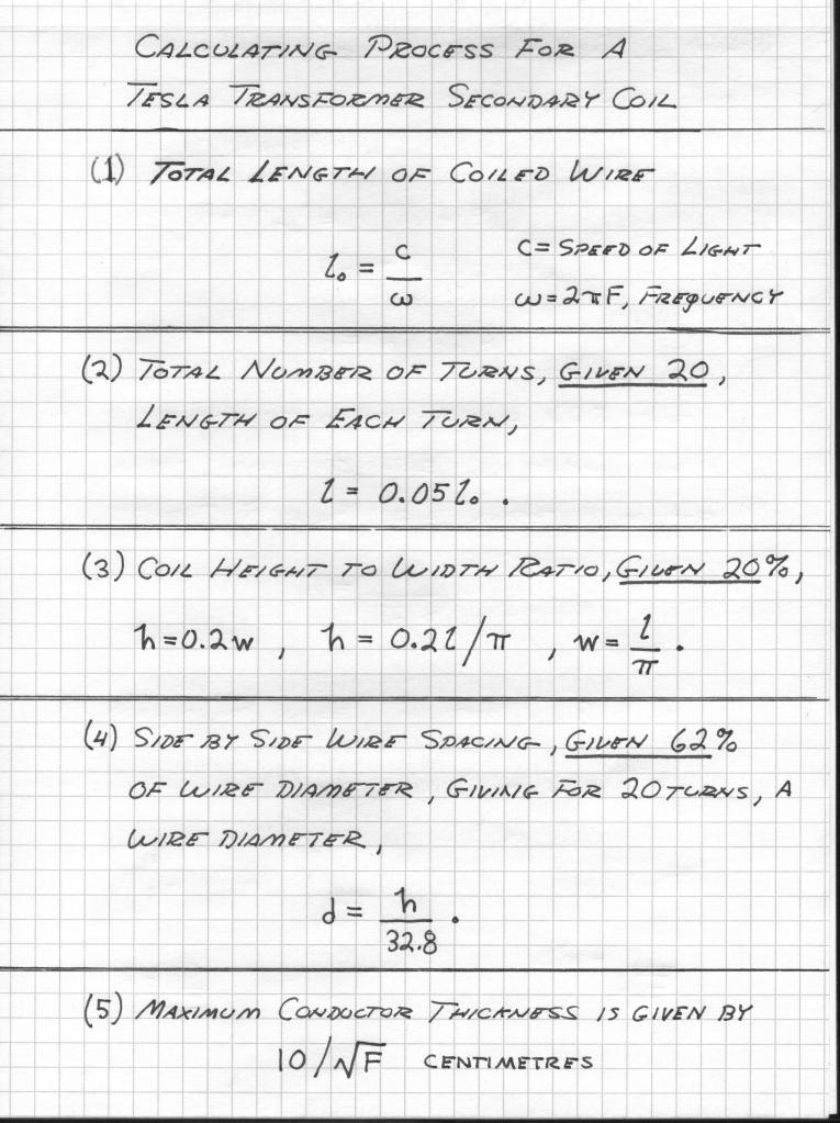
            "The design of the Tesla Transformer starts with the secondary resonant coil. In its resonant mode it is a quadrapolar resonator. Two constants exist in the construction of this solenoidal resonator, one is that the height to length ratio must be 20%, the other is that the side by side spacing of the cylindrical conductor turns is 62% the diameter of the cylindrical conductor. The optimum number of turns is 20 on the secondary, with 2 on the primary. This gives the physical size of the coil for a given frequency. Increasing the number of turns reduces the size of the secondary coil in proportion to the increase in turns. Accordingly the conductor diameter also decreases as the copper is spread out over more windings. The ratio of secondary turns to primary turns must equal a constraint of 10 to 1. For a given number of turns the operating frequency becomes the sole independent variable in coil design.The primary coil is the same diameter as the secondary coil. The ratio of conductor width to coil diameter is 18%.

            The sheet conductor is closely spiralled into two turns, for a secondary of twenty turns. For a conductor thickness as given by the maximum thickness vs frequency the volume of the primary metal must equal the volume of the secondary metal, based upon equal weights for primary and secondary metals. Brass can be 1.7 times thicker than copper, and bronze can be 2.8 times thicker than copper, for a given maximum thickness and frequency.The primary condenser should be made of the same amount of metal as the primary coil. Their weights should be about the same. The connecting leads must be short and the same width as the primary conductor. Large, multiplate air condensers are good, so are metal sheets and glass.The secondary capacitance is best a copper tubing ring around the outside of the H end of the coil. This ring must be open in one spot along its loop so as not to be a shorted turn. The end of the secondary wire connects to this capacity ring. Beer cans make the best elevated capacitors.The finished transformer must operate on a directly connected ground plane. A large plywood table with aluminum foil glued on to it, this covered with a plastic or glass sheet is the minimum required ground plane. Obviously the aluminum plane must be solidly earthed with special attention to minimizing ground lead inductance. In order to light a lamp a more broadcast station style of ground plane is required, but for testing purposes the metallized plywood “ten by” sheet is just fine. Good luck and good crystal set DX ing.


            Hope this helps to get you started?

            -Seb

            Comment


            • #7
              Sample calculations

              OK, based on your suggestions and the calculations you have posted, I can visualize the transformer. It will be small enough to hold in one hand.

              Here is what I have done so far:

              I will be using 750 KHz as my center frequency as an example. This frequency is used by the famous WSB.

              WSB is a 50,000 watt clear channel broadcasting station in Atlanta, GA.

              The antenna is located in Tucker, GA according to Wikipedia.

              Calculation #1

              L = Total length of coiled wire

              L = f/w = 299,792,458 (meter / second) / 2 * PI * 750,000 (/second)

              = 299,792,458 / 2 * 3.14159 * 750,000 (meters) = 63.62 meters = 63.62 meters * .3048 ft / meter

              = 19.39 feet

              Calculation #2

              L = Length of each turn = 19.39 feet / 20 = 0.9695 feet = 11.63 inches

              Calculation #3

              Circumference C = L; Diameter = Circumference / PI = 3.7 inches

              H = Coil height = 0.2 * Diameter = 0.2 * (11.63 inches / PI)

              = 0.74 inches

              Calculation #4

              Max diameter of wire. Space between strands of wire is 62 percent of wire diameter.

              20 turns take 0.74 inches ===> 1 turn takes 0.74 inches / 20 = 0.037 inches

              0.037 inches = 162 percent of wire diameter ===> 100 percent of wire diameter = 0.037 / 1.62

              Wire diameter = 0.02286 inches (max.)

              AWG 23 has a diameter of 0.0226 inches / 0.573 mm.

              AWG 23 has resistance of 66.79 ohms / Km. which is 20.36 mOhms / ft.

              For 19.39 ft, the coil will have 395 mOhms or 0.395 Ohms resistance.

              I thought it would be larger than this. So much for my intuition.
              There is a reason why science has been successful and technology is widespread. Don't be afraid to do the math and apply the laws of physics.

              Comment


              • #8
                Originally posted by wayne.ct View Post
                OK, based on your suggestions and the calculations you have posted, I can visualize the transformer. It will be small enough to hold in one hand.

                Here is what I have done so far:

                I will be using 750 KHz as my center frequency as an example. This frequency is used by the famous WSB.

                WSB is a 50,000 watt clear channel broadcasting station in Atlanta, GA.

                The antenna is located in Tucker, GA according to Wikipedia.

                Calculation #1

                L = Total length of coiled wire

                L = f/w = 299,792,458 (meter / second) / 2 * PI * 750,000 (/second)

                = 299,792,458 / 2 * 3.14159 * 750,000 (meters) = 63.62 meters = 63.62 meters * .3048 ft / meter

                = 19.39 feet

                Calculation #2

                L = Length of each turn = 19.39 feet / 20 = 0.9695 feet = 11.63 inches

                Calculation #3

                Circumference C = L; Diameter = Circumference / PI = 3.7 inches

                H = Coil height = 0.2 * Diameter = 0.2 * (11.63 inches / PI)

                = 0.74 inches

                Calculation #4

                Max diameter of wire. Space between strands of wire is 62 percent of wire diameter.

                20 turns take 0.74 inches ===> 1 turn takes 0.74 inches / 20 = 0.037 inches

                0.037 inches = 162 percent of wire diameter ===> 100 percent of wire diameter = 0.037 / 1.62

                Wire diameter = 0.02286 inches (max.)

                AWG 23 has a diameter of 0.0226 inches / 0.573 mm.

                AWG 23 has resistance of 66.79 ohms / Km. which is 20.36 mOhms / ft.

                For 19.39 ft, the coil will have 395 mOhms or 0.395 Ohms resistance.

                I thought it would be larger than this. So much for my intuition.
                There is a small mistake in your calculations...

                L = Total length of coiled wire

                L = f/w THIS IS WRONG, it should be c/w! (but you have calculated it correctly) = 299,792,458 (meter / second) / 2 * PI * 750,000 (/second)

                = 299,792,458 / 2 * 3.14159 * 750,000 (meters) = 63.62 meters = 63.62 meters * .3048 ft / meter

                = 19.39 feet
                THIS IS WRONG!


                If converted then 63,62 meters gives roughly about 209 feet (63,62x3,28=208,67).

                That shouldn't fit in your hand anymore...

                Remember you need two different setups, one wave, Hertzian, is the over ground wave, the other wave, Telluric, is the under ground wave. These two waves arrive at the point of reception in their own distinct time frames, giving rise to a difference in phase. Hence, multiple rings of interference patterns are produced. Since the Hertzian portion, over ground, time frame is based upon the velocity of light, then the Telluric portion, under ground, time frame gives the Telluric velocity. Two crystal sets, one over ground, one under ground, and a basic oscilloscope , that simple.

                A great link for most information needed is provided in my first answer in this thread. Happy experimenting!

                -Seb
                Last edited by Sebacid; 08-26-2013, 07:37 PM.

                Comment


                • #9
                  Just finished my calculations for my secondary coil and it will be a whopping 76cm in diameter! I am going with 1000Kc/sec Frequency.

                  I finished the work on the wooden bases and supports, all that is left is to bake and laquer them before assembling.

                  My extra coil's diameter/height is going to be 30cm.

                  Some calculations with other stuff is still going on, but I'm going to build two identical coils of the exact same size, one for overground Hertzian wave reception and the other for underground Tellurical wave reception.

                  The coils will be identical but the setup will be different as the goal is to light a 100W lightbulb with the other coil.

                  We'll see how things go once I have built them.

                  -Seb

                  Comment


                  • #10
                    Originally posted by Sebacid View Post
                    Just finished my calculations for my secondary coil and it will be a whopping 76cm in diameter! I am going with 1000Kc/sec Frequency.

                    I finished the work on the wooden bases and supports, all that is left is to bake and laquer them before assembling.

                    My extra coil's diameter/height is going to be 30cm.

                    Some calculations with other stuff is still going on, but I'm going to build two identical coils of the exact same size, one for overground Hertzian wave reception and the other for underground Tellurical wave reception.

                    The coils will be identical but the setup will be different as the goal is to light a 100W lightbulb with the other coil.

                    We'll see how things go once I have built them.

                    -Seb
                    Thinking of replacing solid wooden supports, with hollow pvc tubing (thin) to minimize stray inductance? Any thoughts on this?

                    Comment


                    • #11
                      Hi Sebastian. Yes PVC tubing will be better than wood. Also ideally you should design the coil for a specific frequency/radio station, 1000 kc is a general example. When tuned to different frequencies the magnification factor will alter, the goal is to have highest magnification factor at the intended frequency so different tuning will work against this. Although you will need to experiment to find the highest magnification factor with a given design anyway.

                      For the overground wave reception you should use a normal crystal radio or a normal radio receiver. You need to receive the signal as normal and then measure the difference.
                      http://www.teslascientific.com/

                      "Knowledge is cosmic. It does not evolve or unfold in man. Man unfolds to an awareness of it. He gradually discovers it." - Walter Russell

                      "Once men died for Truth, but now Truth dies at the hands of men." - Manly P. Hall

                      Comment


                      • #12
                        Originally posted by dR-Green View Post
                        Hi Sebastian. Yes PVC tubing will be better than wood. Also ideally you should design the coil for a specific frequency/radio station, 1000 kc is a general example. When tuned to different frequencies the magnification factor will alter, the goal is to have highest magnification factor at the intended frequency so different tuning will work against this. Although you will need to experiment to find the highest magnification factor with a given design anyway.

                        For the overground wave reception you should use a normal crystal radio or a normal radio receiver. You need to receive the signal as normal and then measure the difference.
                        Hi Dr. Green,

                        Thank you for your insight, I will have to do some searching on a AM radio station near me (Finland). The problem here is that almost all of the broadcasting stations have ceased using the AM frequencys. I think the nearest one is in Holland?! Not sure on this, must check.

                        In the calculations for the extra coil, I get a totally different total lenght of coil if I use the formulae by Eric to calculate it?

                        Tesla's Colorado extra coil had the same amount of wire as the secondary (800m). Should I go with this or trust the formulae?

                        Thanks again,

                        -Seb

                        Post edit:

                        Found a radio station from Sweden, Stockholm radio that broadcasts at 1710Khz AM frequency. I think it is still operational, so I will try working with this frequency. The last AM radiostation in Finland ceased to operate in 2007. Any other known operational frequencys are welcome!
                        Time to do the calculations again!
                        Last edited by Sebacid; 08-30-2013, 12:55 PM. Reason: Adding information

                        Comment


                        • #13
                          I forgot to mention, use white or clear etc plastic rods. Apparently to make black and grey they put carbon in it, so that won't be good.

                          Eric's design is different to Tesla's. Eric's theory involves concatenated resonance with the extra coil as a distributed network, whereas Tesla's is lumped. So it's completely experimental. I've tried 3 different extra coil variations, and Eric's latest comments on it was that the secondary might need to be of a lower inductance, so my latest design is a bit different. I have 17 turns secondary with 15% height to diameter ratio, and the extra coil, when calculating wavelength from frequency and speed of light, has 1.19 times longer wire length because of the "faster than light" propagation, wire length is extended to bring the frequency back down.

                          [edit] Probably the easiest way to find whether a radio station is operational and suitable or not is to use a radio. When you find one then you can find info on it on the internet.
                          Last edited by dR-Green; 08-30-2013, 01:57 PM.
                          http://www.teslascientific.com/

                          "Knowledge is cosmic. It does not evolve or unfold in man. Man unfolds to an awareness of it. He gradually discovers it." - Walter Russell

                          "Once men died for Truth, but now Truth dies at the hands of men." - Manly P. Hall

                          Comment


                          • #14
                            for accurate time comparison how do you compensate and adjust for delay differences that result from the inherent design differences between the telluric and atmospheric versions?

                            and one more....

                            how do we calculate the maximum theoretical (ideal conditions) power that can be drawn from a transmitter with a particular receiver design/situation
                            Last edited by Kokomoj0; 08-30-2013, 05:48 PM.

                            Comment


                            • #15
                              Originally posted by Kokomoj0 View Post
                              for accurate time comparison how do you compensate and adjust for delay differences that result from the inherent design differences between the telluric and atmospheric versions?
                              Use an oscillator and tune both receivers to be in phase.

                              Originally posted by Kokomoj0 View Post
                              how do we calculate the maximum theoretical (ideal conditions) power that can be drawn from a transmitter with a particular receiver design/situation
                              Beats me. How's your geological skills?
                              http://www.teslascientific.com/

                              "Knowledge is cosmic. It does not evolve or unfold in man. Man unfolds to an awareness of it. He gradually discovers it." - Walter Russell

                              "Once men died for Truth, but now Truth dies at the hands of men." - Manly P. Hall

                              Comment

                              Working...
                              X