Getting Better
I'm getting lonely. Is anyone else getting ANY results out of the crystal radio initiative setup?
-
Why?
As the distance between the primary and secondary is increased the resonant frequency of the coil increases ~5-10kHz per inch and the amperage measured between the can and the top of the secondary also goes up.
Any ideas?
I'm playing with the secondary and primary like in
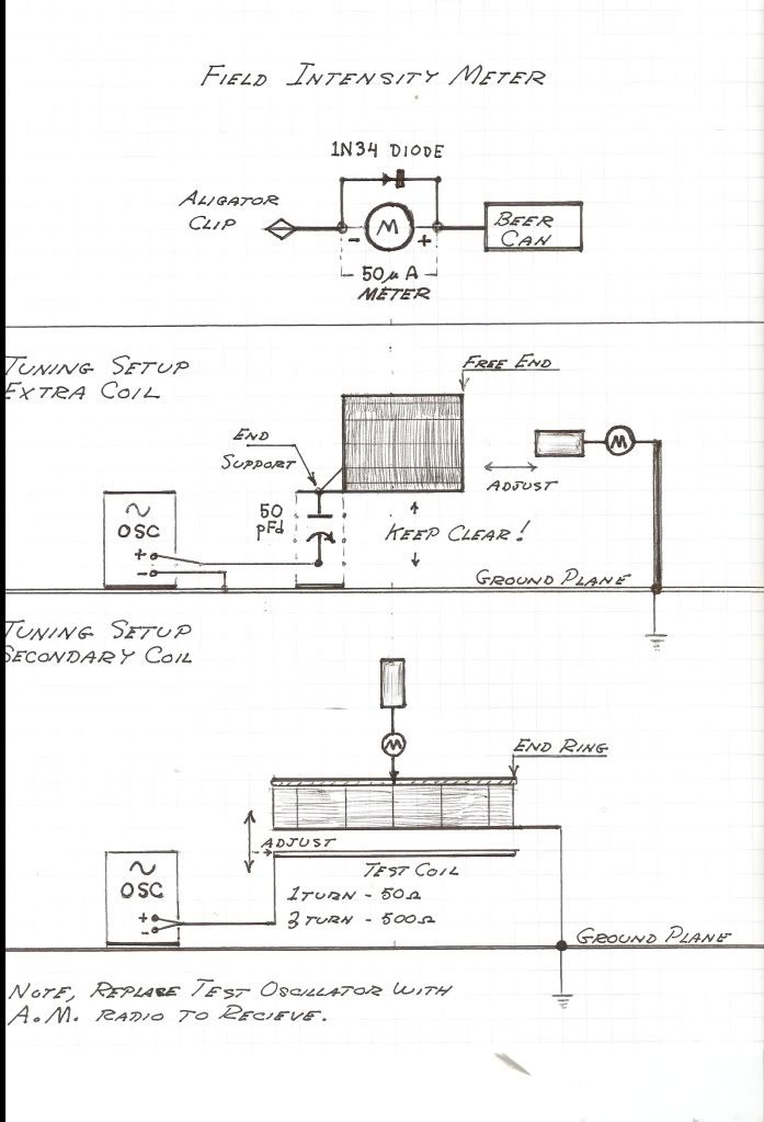
I did not post this in the Dollard thread because I am missing the split ring on top. I am also using more of a current indicator with an adjustable range for readings so there are no actual values I cam use.
Currently the best frequency is 2200kHz. But this will change(+\-500kHz) depending on the evil clip leads being used and how they are laid out. I flattened some 14 gauge and need to get that soldered in place.Leave a comment:
-
Last edited by Kokomoj0; 04-12-2012, 11:41 PM.Leave a comment:
-
That's what I'm trying to figure out.Originally posted by Kokomoj0 View Post
File:Replica-of-first-transistor.jpg - Wikipedia, the free encyclopedia
I like this picture. It says alot about what we can do once we learn how.
I've learned alot about working with radio frequency just tuning the basic crystal radio.
So far my TRT is a Just a large crystal radio with two coils. But it will light an LED continuously all day when the station is @ 10kW. It's dim but it's on. Not blinking(filter cap), one germanium diode and led across the secondary.
It may all be just standard RF reception. I don't know yet. I didn't think that would be possible. But it's not tuned yet. Unless I got it right the first rime.
The full wave should help as long as the extra voltage drop does not cause problems.
Thanks,

Leave a comment:
-
I said this in the other thread, make a ful wave bridge out of your germ diodes and use filter caps. I would be shocked if you couls pull in any amount of power like that because of the low current density. The whole idea of pulling "significant" power off of these radio stations seems absurd to me.Leave a comment:
-
Originally posted by jake View Post
I have posted a number of low power Joule thief circuits. This may be a good choice ... no toroid Joule thief 3 - YouTube
Rectify radio output with diode and capacitor. Run Joule thief from capacitor. You will need at least 0.5 to 0.7 volts to run Joule thief. You do not need 10,000 uF capacitor, use what ever you have. Reduce resistor value to make LED brighter.
Same circuit with toroid >> 2 uA Joule thief - YouTubeLast edited by xee2; 04-10-2012, 02:36 AM.Leave a comment:
-
I have a 10kw AM station about 6 miles away. I looked up mrflathunter and found two more that show similar results of dimly lighting LEDs with nothing but a coil and diode. Do you have any advice on how to run a joule theif off these? I listed the voltages I can measure above.Originally posted by xee2 View PostLeave a comment:
-
Not unless the antenna was near a strong RF source. Do you have any radio or TV transmit towers near you? If you watch MrFlathunter (Seth) videos you will see he is able to light things with his passive resonator but only if near the transmitting exciter.Originally posted by jake View PostLeave a comment:
-
I this typical RF
On a TRT secondary and extra coil:
{extra coil}------{secondary}-----Ground
If I tap between the extra coil and secondary run a germanium diode, my body, and LED in series to ground I can dimly light the led.
{top of secondary}--{+germanium diode-}---{right hand}---{body}----{left hand}---{+LED-}----Ground
The LED will show light and its getting brighter the more I learn.
Is this a normal RF???
I can see 2.2v avg across the LED when I leave my body out of the circuit. 2.6max and 2.5pp. These are all estimated because the values fluctuate with the broadcast signal. They stabalize a bit when I put a 330pF cap across the LED.
Also adding capacitance to the lead that goes from secondary to diode in the form of me touching the insulated lead has a large effect. I was able to recreate this effect using a the piece of aluminium(i.e. the ground terminals of a dule gang air variable cap). Using the variable cap the way it should be used did not work. Made things completely stop working and the voltage dissapear. I found this on accident.
So is this something you would see on a typical crystal radio?
Is it RF or somethine else?Leave a comment:
-
Here's a decent explanation on manifolds.
Manifold - Wikipedia, the free encyclopediaLeave a comment:

Leave a comment: