Announcement

Collapse
No announcement yet.

COP 17 Heater | Rosemary Ainslie

Collapse
This topic is closed.
X
This is a sticky topic.
X
X
 
  • Filter
  • Time
  • Show
Clear All
new posts

  • Considering the NE555 output stage and its specifications, it has a 100ns rise and fall time when drives a load that has a maximum of 15-20pF capacitance.
    In this setup here the power MOSFET type has at least 1500-1800pF capacitance between its gate source and switching speed must suffer towards the microsec speeds.
    The series 100 Ohm in the gate circuit (or in case of Aaron the 1 kOhm potmeter) also works against the switching speed but without it it would be more difficult to make this setup self-oscillate. (This resistor tends to raise the gate impedance, this is one condition to regeneration, the frequency of which is the parallel resonant frequency of the drain circuit where mainly the inductance of the load resistor and the drain source capacitance constitutes a parallel resonant circuit.)

    The reason I mention switching speed above is that without a relatively higher switching speed the flyback pulse is not likely to raise much, maybe some 200-300V, depending on also the resistor self inductance of course V=L*(dI/dt). This means it is very far from any breakdown if the MOSFET ratings are in 900-1000V range.

    rgds, Gyula
    Last edited by gyula; 08-01-2009, 10:56 PM. Reason: some addition

    Comment


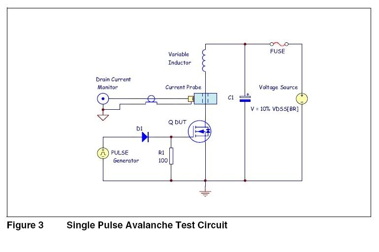
    • Originally posted by Aaron View Post
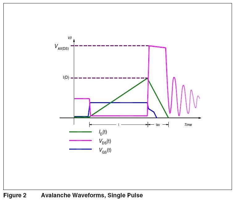
      Diagram to help visualize Harvey's explanation:


      @Aaron, Rosemary and Harvey

      I saw this diagram and it looks very similar to what Aaron is portraying ....

      Infineon Technologies - Introduction to Avalanche conciderations for CoolMos Mosfet's


      Interesting information ..... there's that pesky ground connection again .....

      Best Regards,
      Glen
      Open Source Experimentalist
      Open Source Research and Development

      Comment


      • avalanche

        Hi Harvey,

        On all these Fuji mosfets and other similar ones in the series. I cannot find one single reference to repetitive-avalanche. There is however, very clear specs only on non-repetitive avalanche.

        So it appears there can be avalanche in a mosfet without it being repetitive and being "avalanche proof" seems to indicate that these mosfets can only handle non-repetitive avalanches. Therefore, it seems to me that avalanche and oscillation do not go hand in hand because otherwise, what is the point of a non-repetitive avalanche? And from the datasheets I see, if it is repetitive it will be listed as well as the non-repetitive specs.

        Perhaps someone can ask TK to demo his mosfet and show on the scope that particular mosfet oscillating at over 100kHz - overlaid on the timing duty cycle and frequency.

        If TK's recommended mosfet can show oscillation or that there can be some datasheet found somewhere that indicates repetitive avalanche in addition to non-repetitive avalanche, I'll change the notation on my schematic, will change my post about not using TK's mosfet and I'll edit my post at ou.com
        Last edited by Aaron; 08-01-2009, 11:43 PM.
        Sincerely,
        Aaron Murakami

        Books & Videos https://emediapress.com
        Conference http://energyscienceconference.com
        RPX & MWO http://vril.io

        Comment


        • Originally posted by jas_bir77 View Post
          i thought since we are utilising back emf so why not enhance to a great length and then use it sorry if i went off topic.

          jasbir
          Not sure, if you went off topic, but seems, here still need to do some Proofs for some Experts, that they can believe something.

          But there are 2 Things, i still miss.
          Once, there been nowhere the Claims, that the Batteries still should get loaded.
          It is more about, to create Heat, charging up the Batts, seems should be a Extra Effect.

          And second is, that at this 'Proof' for COP 17,
          there is never included, to calculate the Heat what is created with the Amount of used Energy.
          Only do the measurements across the Shunt. That still dont sounds right.
          But well, our Experts what we got here surely know, what they are talking, maybe?

          Anyway. i got few of this Transformers from Microwaves, catched few from a Junkyard, they are not to hard to get.
          From this boths Coils i get nice Zaps even from a 9V Block, so they still can generate Power.
          And please, let the Argument stick, its only transformed Current, i do know that allready.

          And about the Magnets is the same, what i found out lately too.
          When you put a Magnet between a connection, it can inprove the Current what is running though,
          but it depends at the Place, where you put it, and wich Direction the Poles face too.
          Its like, as if the PMfield push the Current, and let me guess, i think, North, did face to Minus, like Current usual create the EM Field.
          Theorizer are like High Voltage. A lot hot Air with no Power behind but they are the dead of applied Work and Ideas.

          Comment


          • Repetitive Avalanche Rated Mosfets: HEXFET III

            Originally posted by FuzzyTomCat View Post
            Hi everyone,

            I found another possible substitution for the MOSFET ...

            International Rectifier IRFPG50

            ST Microelectronics STW9N150

            N-channel 1500 V - 1.8 Ω - 8 A - TO-247
            very high voltage PowerMESH™ Power MOSFET
            Single pulse avalanche energy - 720

            @ Aaron and Rosemary ....... look at Figure 4 Typical Output Characteristics and Figure 5 Typical Transfer Characteristics everything else appears fairly close.

            Best Regards,
            Glen
            Thanks Glen!

            Here are your four finds:
            Fairchild Semiconductor - FQH8N100C
            Fairchild Semiconductor - FQAF11N90C
            International Rectifier IRFPG50

            ST Microelectronics STW9N150

            --------------------------------------------

            On Harvey's post about HEXFET III: A New Generation of Power MOSFETs, the entire table at the top of page 2 are all Repetitive Avalanche Rated Mosfets!

            IRF510
            IRF710
            IRF520
            IRF720
            IRF820
            IRF530
            IRF730
            IRF830
            IRF540
            IRF740
            IRF840
            IRF450
            IRF460
            Sincerely,
            Aaron Murakami

            Books & Videos https://emediapress.com
            Conference http://energyscienceconference.com
            RPX & MWO http://vril.io

            Comment


            • Keep in mind too, that as I understand Rosemary's claim, it has to do with conserved energy in the load resistor being stored at the point of manufacture, and that it would leak into the field and add to it resulting in a breakdown of the load resistor. Please correct me if I am wrong here.harvey

              Yes.

              EDIT Harvey I keep missing you. Time zones? Whatever. Very happy with that first sentence.

              ANOTHER EDIT. I just keep coming back to that sentence. I think it's a first. Just so chuffed.
              Last edited by witsend; 08-02-2009, 05:11 AM.

              Comment


              • @gyula

                Originally posted by gyula View Post
                Considering the NE555 output stage and its specifications, it has a 100ns rise and fall time when drives a load that has a maximum of 15-20pF capacitance.
                In this setup here the power MOSFET type has at least 1500-1800pF capacitance between its gate source and switching speed must suffer towards the microsec speeds.
                The series 100 Ohm in the gate circuit (or in case of Aaron the 1 kOhm potmeter) also works against the switching speed but without it it would be more difficult to make this setup self-oscillate. (This resistor tends to raise the gate impedance, this is one condition to regeneration, the frequency of which is the parallel resonant frequency of the drain circuit where mainly the inductance of the load resistor and the drain source capacitance constitutes a parallel resonant circuit.)

                The reason I mention switching speed above is that without a relatively higher switching speed the flyback pulse is not likely to raise much, maybe some 200-300V, depending on also the resistor self inductance of course V=L*(dI/dt). This means it is very far from any breakdown if the MOSFET ratings are in 900-1000V range.

                rgds, Gyula
                Hi Gyula,

                Thanks for your input.

                I have a few questions if you don't mind.

                Is there a 555 version with faster rise time for higher capacitance load?

                What about using the 555 to trigger a piggyback transistor like some darlington arrangement or something on the mosfet or would that be redundant and actually slow it down. I can sent the output of 555 thru a h11d1 isolator if necessary.

                Actually the series resistor at the gate is a 1K variable pot. With zero resistance the switching time is much faster and the spike is quite a bit more.

                However, on the applied field of the coil.... when power is turned off, nature brings it to equilibrium and we get the collapsing spike but the spike doesn't stop at the ground or zero. It goes thru the floor way negative. Nature then tries to bring the negative spike to equilibrium and sends it to zero but it doesn't stop there it goes positive and repeat until it rings down to zero. I'm sure you know this but just to illustrate.

                On my scope pic with zero resistance, the positive spike that follows is pretty big and that repeats kind of in a rough manner. With just a bit of resistance, it brings that down until there is a very clean negative spike and then very symmetrical ringing afterward.

                Again, with zero resistance, the spike is like you say, able to go to a few hundred volts. With some resistance, I can get the spike to 4 times the battery voltage or around 100 volts without having any positive spike going above the battery...just nice smooth symmetrical ringing.

                Do you see any way around this limitation? Or a way to enhance what I'm already doing with the 555?
                Sincerely,
                Aaron Murakami

                Books & Videos https://emediapress.com
                Conference http://energyscienceconference.com
                RPX & MWO http://vril.io

                Comment


                • Do you see any way around this limitation? Or a way to enhance what I'm already doing with the 555?[/quote]


                  Hi Aaron,


                  Have you tried a neo magnet in different parts of this circuit yet?
                  I think you can figure out where placing that, might have an influence on the circuit.Just a thought .


                  -Gary

                  Comment


                  • Originally posted by witsend View Post
                    Keep in mind too, that as I understand Rosemary's claim, it has to do with conserved energy in the load resistor being stored at the point of manufacture, and that it would leak into the field and add to it resulting in a breakdown of the load resistor. Please correct me if I am wrong here.harvey

                    Yes.

                    EDIT Harvey I keep missing you. Time zones? Whatever. Very happy with that first sentence.

                    ANOTHER EDIT. I just keep coming back to that sentence. I think it's a first. Just so chuffed.


                    Hoppy

                    Comment


                    • Time Zones

                      Originally posted by witsend View Post
                      Keep in mind too, that as I understand Rosemary's claim, it has to do with conserved energy in the load resistor being stored at the point of manufacture, and that it would leak into the field and add to it resulting in a breakdown of the load resistor. Please correct me if I am wrong here.harvey

                      Yes.

                      EDIT Harvey I keep missing you. Time zones? Whatever. Very happy with that first sentence.

                      ANOTHER EDIT. I just keep coming back to that sentence. I think it's a first. Just so chuffed.
                      My TZ is GMT-8, so I think that may be part of it. Of course it's probably around 10:00AM where you are right now...o.O (give or take an hour or two).

                      Still thinking on your original theory and a solid way to substantiate it that would be palatable to mainstream academia. We may find it useful to use something like the BatCap line Super Cap SuperCap 100 that can be charged to a very specific known value and then dump that through an inductor into another empty SuperCap. By choosing values that support a resonant action, the two SuperCaps should charge each other alternately until they are balanced. In that process, any lost energy should manifest itself as heat in the inductor. Using someone's idea from the forum here, place the inductor in an oil bath and monitor the caloric differential. After enough runs, solid data should emerge that would show both the gains and structural decay. I would guess that at least 20 or 30 runs would be required at a minimum. In this way, we wouldn't be introducing other uncontrollable variables, like battery chemical reactions, spurious oscillations, thermodynamic issues in the control circuits etc. It would be simply two very large capacitors and an inductor in a tuned resonant tank circuit. Put the known energy in one and let it ring until both are balanced. If energy escapes from the inductive structure into the field in your existing circuit, it should be measurable as well in this test - I think

                      "Amy Pond, there is something you need to understand, and someday your life may depend on it: I am definitely a madman with a box." ~The Doctor

                      Comment


                      • Originally posted by Aaron View Post
                        Hi Gyula,

                        Thanks for your input.

                        I have a few questions if you don't mind.

                        Is there a 555 version with faster rise time for higher capacitance load?

                        What about using the 555 to trigger a piggyback transistor like some darlington arrangement or something on the mosfet or would that be redundant and actually slow it down. I can sent the output of 555 thru a h11d1 isolator if necessary.

                        Actually the series resistor at the gate is a 1K variable pot. With zero resistance the switching time is much faster and the spike is quite a bit more.

                        However, on the applied field of the coil.... when power is turned off, nature brings it to equilibrium and we get the collapsing spike but the spike doesn't stop at the ground or zero. It goes thru the floor way negative. Nature then tries to bring the negative spike to equilibrium and sends it to zero but it doesn't stop there it goes positive and repeat until it rings down to zero. I'm sure you know this but just to illustrate.

                        On my scope pic with zero resistance, the positive spike that follows is pretty big and that repeats kind of in a rough manner. With just a bit of resistance, it brings that down until there is a very clean negative spike and then very symmetrical ringing afterward.

                        Again, with zero resistance, the spike is like you say, able to go to a few hundred volts. With some resistance, I can get the spike to 4 times the battery voltage or around 100 volts without having any positive spike going above the battery...just nice smooth symmetrical ringing.

                        Do you see any way around this limitation? Or a way to enhance what I'm already doing with the 555?
                        Hi Aaron,

                        Well, there is the CMOS version of the NE555, it is the LMC555CN or TC555C or TLC555C, see data sheet on the first: http://www.national.com/ds/LM/LMC555.pdf
                        It has a 15ns fall and rise time output driving capability but still at 10pF load capacitor so it is much better than the bipolar IC version but still not enough.

                        The remedy can be using dedicated MOSFET driver chips for the job like you may see here for instance: Special Function IC's - Microchip - TC4420CPA
                        It is able to drive even a 10nF capacitive load and has a 25ns rise and fall time when the capacitive load is 2.5nF.
                        (One notice though: if you wish to use these types than you have altered the original Rosemary circuit.)

                        There is no other good solution at the driver side besides the fast dedicated drivers (they are designed specially for this purpose), if you consider using optocouplers (h11d1) then you certainly make backward steps, this type is way too slow. Again, there are faster optocouplers but they are more expensive than a MOSFET driver.

                        Regarding the rest of your thoughts and findings. In conventional gate driver circuits the inserted series resistor in the gate (usually a few tens of Ohm like 33 or 47 or max 100 Ohm) is expected to reduce any condition for oscillation, or limit a little the gate driving current which flows when the nanofarad capacitor of the gate-source is charged and then discharged, during the ON and then the OFF switching sequencies.
                        So the role of this resistor here is controversial, it would be good to know the original aim of the team with this resistor.

                        I have just seen your answer in poynt99's thread where the function of the series 100 Ohm potmeter becomes explained by the Rosemary team.
                        However you wrote: "...there are mosfets specifically designed to self-oscillate as there are mosfets that are designed to specifically not oscillate. When it oscillates, it may encounter avalanche." I can only agree with your second statement (When it oscillates...), the first cannot be true.

                        rgds, Gyula

                        Comment


                        • @guyla timing signal and oscillation

                          Originally posted by gyula View Post
                          Hi Aaron,

                          Well, there is the CMOS version of the NE555, it is the LMC555CN or TC555C or TLC555C, see data sheet on the first: http://www.national.com/ds/LM/LMC555.pdf
                          It has a 15ns fall and rise time output driving capability but still at 10pF load capacitor so it is much better than the bipolar IC version but still not enough.

                          The remedy can be using dedicated MOSFET driver chips for the job like you may see here for instance: Special Function IC's - Microchip - TC4420CPA
                          It is able to drive even a 10nF capacitive load and has a 25ns rise and fall time when the capacitive load is 2.5nF.
                          (One notice though: if you wish to use these types than you have altered the original Rosemary circuit.)

                          There is no other good solution at the driver side besides the fast dedicated drivers (they are designed specially for this purpose), if you consider using optocouplers (h11d1) then you certainly make backward steps, this type is way too slow. Again, there are faster optocouplers but they are more expensive than a MOSFET driver.

                          Regarding the rest of your thoughts and findings. In conventional gate driver circuits the inserted series resistor in the gate (usually a few tens of Ohm like 33 or 47 or max 100 Ohm) is expected to reduce any condition for oscillation, or limit a little the gate driving current which flows when the nanofarad capacitor of the gate-source is charged and then discharged, during the ON and then the OFF switching sequencies.
                          So the role of this resistor here is controversial, it would be good to know the original aim of the team with this resistor.

                          I have just seen your answer in poynt99's thread where the function of the series 100 Ohm potmeter becomes explained by the Rosemary team.
                          However you wrote: "...there are mosfets specifically designed to self-oscillate as there are mosfets that are designed to specifically not oscillate. When it oscillates, it may encounter avalanche." I can only agree with your second statement (When it oscillates...), the first cannot be true.

                          rgds, Gyula
                          Hi Gyula,

                          I'll look into the other 555 and even the dedicated driver. Peter told me about them. I never had a need for them. I'll experiment with that later after more work on the replication.

                          A faster optocoupler is something I'll look into as well. Thanks!

                          So you agree that when a mosfet is in oscillation, that is may encounter avalanche.

                          My first statement has 2 parts.

                          The first is that there are mosfets that are made to allow for oscillation - as it is implied by the fact that some mosfets do oscillate.

                          The second is that there are mosfets that have built in safeguards against self-oscillation. I posted numerous industry references discussing this safeguard feature against self-oscillation - which they say also prevents "false triggering". There are a lot of references to this in the datasheets, etc...

                          Do you disagree with both of those?

                          If you disagree with the first part, then I can say there are simply some mosfets that oscillate as this would be a fact.

                          With the second, I can find the post in this thread that I put with references to various sources discussing mosfets with anti-oscillation protection built in.

                          Please let me know,
                          Thanks!
                          Sincerely,
                          Aaron Murakami

                          Books & Videos https://emediapress.com
                          Conference http://energyscienceconference.com
                          RPX & MWO http://vril.io

                          Comment


                          • Originally posted by gyula View Post
                            Hi Aaron,

                            Well, there is the CMOS version of the NE555, it is the LMC555CN or TC555C or TLC555C, see data sheet on the first: http://www.national.com/ds/LM/LMC555.pdf
                            It has a 15ns fall and rise time output driving capability but still at 10pF load capacitor so it is much better than the bipolar IC version but still not enough.

                            The remedy can be using dedicated MOSFET driver chips for the job like you may see here for instance: Special Function IC's - Microchip - TC4420CPA
                            It is able to drive even a 10nF capacitive load and has a 25ns rise and fall time when the capacitive load is 2.5nF.
                            (One notice though: if you wish to use these types than you have altered the original Rosemary circuit.)

                            There is no other good solution at the driver side besides the fast dedicated drivers (they are designed specially for this purpose), if you consider using optocouplers (h11d1) then you certainly make backward steps, this type is way too slow. Again, there are faster optocouplers but they are more expensive than a MOSFET driver.

                            Regarding the rest of your thoughts and findings. In conventional gate driver circuits the inserted series resistor in the gate (usually a few tens of Ohm like 33 or 47 or max 100 Ohm) is expected to reduce any condition for oscillation, or limit a little the gate driving current which flows when the nanofarad capacitor of the gate-source is charged and then discharged, during the ON and then the OFF switching sequencies.
                            So the role of this resistor here is controversial, it would be good to know the original aim of the team with this resistor.

                            I have just seen your answer in poynt99's thread where the function of the series 100 Ohm potmeter becomes explained by the Rosemary team.
                            However you wrote: "...there are mosfets specifically designed to self-oscillate as there are mosfets that are designed to specifically not oscillate. When it oscillates, it may encounter avalanche." I can only agree with your second statement (When it oscillates...), the first cannot be true.

                            rgds, Gyula
                            The bottom line here is that if the mosfet is not driven correctly as designed to be, taking into consideration gate capacitance, the device is not switching efficiently. Any attempt to use the resulting effects of this in an attempt to prove high COP in the system in which the mosfet is used, only goes to complicate measurements and invoke criticism of test method.

                            Hoppy

                            Comment


                            • Originally posted by Harvey View Post
                              My TZ is GMT-8, so I think that may be part of it. Of course it's probably around 10:00AM where you are right now...o.O (give or take an hour or two).

                              Still thinking on your original theory and a solid way to substantiate it that would be palatable to mainstream academia. We may find it useful to use something like the BatCap line Super Cap SuperCap 100 that can be charged to a very specific known value and then dump that through an inductor into another empty SuperCap. By choosing values that support a resonant action, the two SuperCaps should charge each other alternately until they are balanced. In that process, any lost energy should manifest itself as heat in the inductor. Using someone's idea from the forum here, place the inductor in an oil bath and monitor the caloric differential. After enough runs, solid data should emerge that would show both the gains and structural decay. I would guess that at least 20 or 30 runs would be required at a minimum. In this way, we wouldn't be introducing other uncontrollable variables, like battery chemical reactions, spurious oscillations, thermodynamic issues in the control circuits etc. It would be simply two very large capacitors and an inductor in a tuned resonant tank circuit. Put the known energy in one and let it ring until both are balanced. If energy escapes from the inductive structure into the field in your existing circuit, it should be measurable as well in this test - I think

                              Hi Harvey,

                              I think you suggest a good idea on using the Farad value capacitors. Though normally the energy transfer between two caps involves a 50% loss, this loss can be reduced significally by tactically choosing the component values, like member poynt99 has pointed out in his earlier pdf file at overunity.com, though even a 50% loss could be tolerated in the case here, being the claim of COP of 17 or higher.
                              (by the way I suggested the oil bath test you remember )

                              Thanks, Gyula

                              Comment


                              • results are the bottom line

                                Originally posted by Hoppy View Post
                                The bottom line here is that if the mosfet is not driven correctly as designed to be, taking into consideration gate capacitance, the device is not switching efficiently. Any attempt to use the resulting effects of this in an attempt to prove high COP in the system in which the mosfet is used, only goes to complicate measurements and invoke criticism of test method.

                                Hoppy
                                If it does it, it simply does it. Period.
                                Sincerely,
                                Aaron Murakami

                                Books & Videos https://emediapress.com
                                Conference http://energyscienceconference.com
                                RPX & MWO http://vril.io

                                Comment

                                Working...
                                X