Announcement

Collapse
No announcement yet.

COP 17 Heater | Rosemary Ainslie

Collapse
This topic is closed.
X
This is a sticky topic.
X
X
 
  • Filter
  • Time
  • Show
Clear All
new posts

  • Hi Aaron. Many thanks for the comments in support of the thesis.

    Whatever the explanation of this effect, in terms of classical analysis - and albeit at comparatively small measurements - results do seem to support the possibility that currrent flow returns to the supply source with zero net loss to the mass or the material at the supply. Alternatively the voltage developed during the on phase of the cycle seems to generate a second identical cycle. In fact, my interest in this waveform is precisely because of those symmetries. The cooling effect seems to have been required by Quantum and Classical theorists - according to Harvey's references. The evidence of heat at the switching components conforms to classical. But the transfer of any energy here, at no quantifiable loss of energy to the supply? That, I believe, is breaking into new territory. Hopefully, it points to our elusive zero point energy - whether or not mainstream see this as the flow of my little zipons.
    Last edited by witsend; 08-29-2009, 07:45 AM. Reason: another point

    Comment


    • Smoke Test:

      Decided to use the LM555 from national and balance out the spiky output with the inductive trimpot. The frequency and duty cycle are exact to the Quantum specs. I haven't measured the inductance of the resistor but its resonant ring is about 916,666 Hz ... if these tired brain cells did the math right. 5.5 cycles in 6µS. For this test I used a single 12V battery and no 'shunt' resistors. The circuit configuration is the Proposed Changes circuit with modified trimpots to 10K instead of 50K and the off-time pad resistor is 150K instead of 100K.

      Scope Settings :
      1 div = 1cm
      Sweep Setting: 5µs/cm
      CH A 5V/div : DC coupled : offset 1cm above center line : Probe x 1
      CH B 1V/div : DC coupled : offset 4cm below center line : Probe x 10
      Sweep Magnification 5x or 1µs/cm

      CH A Ref B(-) : Probe Loc: IRFPG50 Gate (100 Ohm resistor between probe and gate)
      CH B Ref B(-) : Probe Loc: IRFPG50 Drain (physical connection on load resistor)

      The ringing centers around B(+) and never actually dips below B(-) due to the body diode in the IRFPG50. The 16µs gate pulse is more than enough to charge this inductor as can be seen in the flat along the bottom. There is a noticeable delay between the gate directive to turn off the HEXFET and the inductive collapse resulting in an 80V spike followed by the ringing. It is much longer than the charging time of the inductor.

      Larger Pic

      I experimented with a range of duty cycles and gate resistances - in this configuration I could not get the aperiodic oscillation as of yet. I will try some other frequencies and duty cycles on Sunday. There was no apparent heating or cooling in the resistor or 555, both remained at ambient throughout several hours of periodic testing. The dissipation of these two devices seems to be more than enough for the tested duty cycle and frequency with no aperiodic action.

      Cheers,


      EDIT: Oh, I almost forgot - All the smoke stayed in all the parts so everything still works.
      Last edited by Harvey; 08-29-2009, 09:11 AM. Reason: Forgot to mention the lack of smoke.
      "Amy Pond, there is something you need to understand, and someday your life may depend on it: I am definitely a madman with a box." ~The Doctor

      Comment


      • Hi everyone,

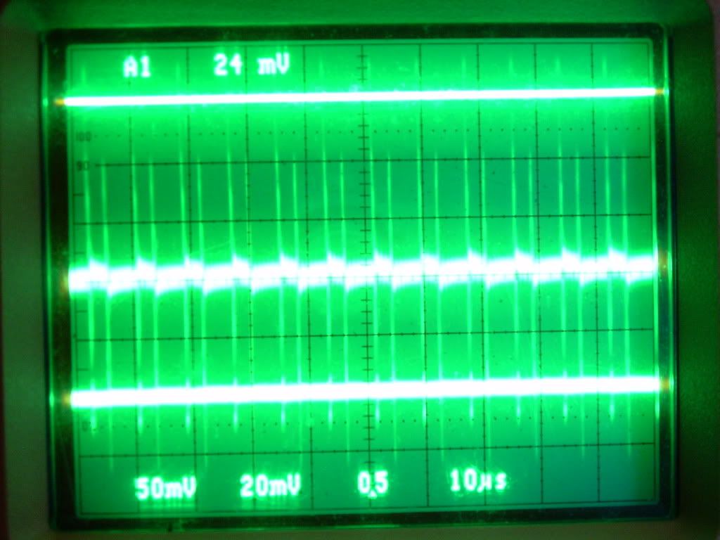
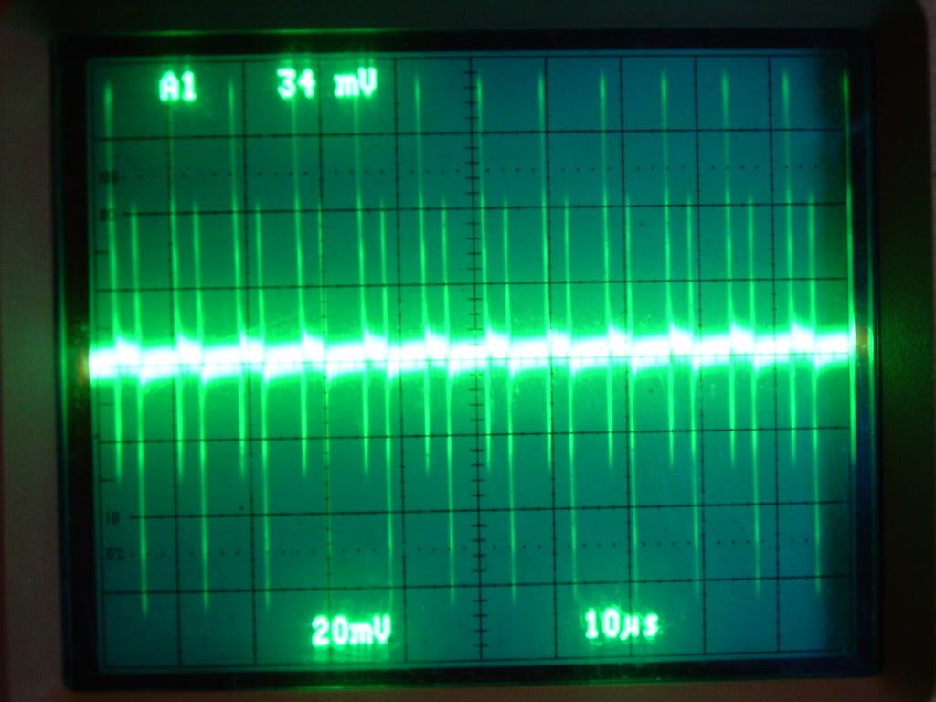
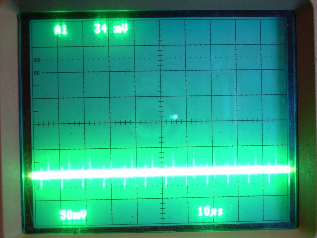
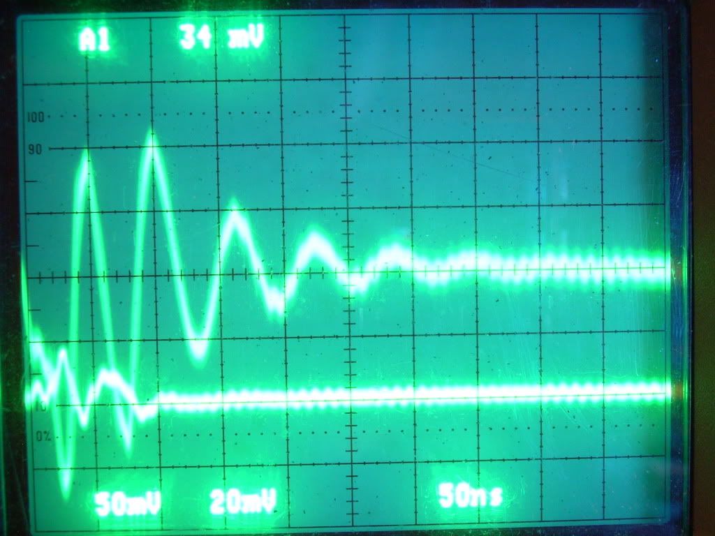
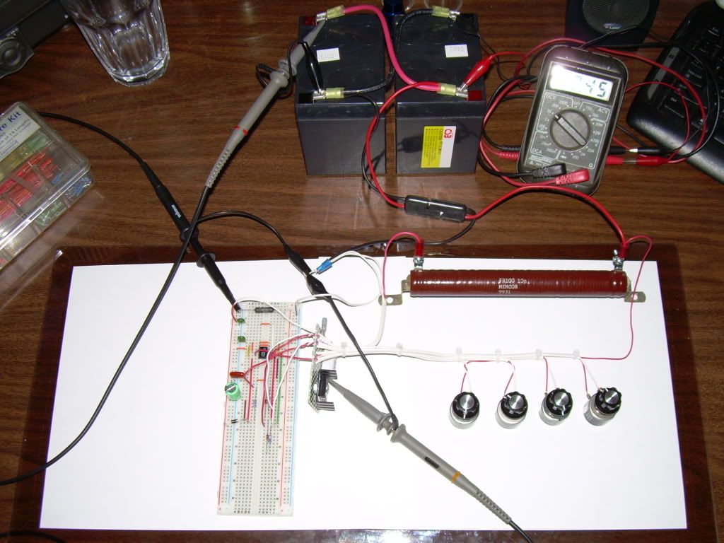
        I acquired the correct parts for the "Ainslie-Murakami Negative Dominant Waveform Generator" put it all together, I used the information from the PDF file "Ainslie-Murakami Negative Dominant Waveform Generator" with the 1 ohm resistor not the RAI 552.UT-5 .25 ohm 5% (non inductive calibrated current sensing resistor) with the presets for the potentiometers -

        • Gate resistance: 53 ohms
        • On pot resistance: 32.8 ohms
        • Off pot resistance: 293.9 ohms
        • NE555N power adjustment pot resistance: 93.1 ohms
        • NE555N timer duty cycle: 55%
        • NE555N timer frequency: 915 kHz
        • Actual run frequency: 1.17 MHz

        Aarons connection points for the scope -

        Channel 1 ground is on battery negative side of 0.25 ohm shunt and probe is at 555 negative rail side of shunt.

        Channel 2 ground is on battery negative side of 1 ohm shunt and probe is at mosfet source side of shunt. The 1 ohm shunt replaces the 0.25 ohm shunt that I was using for sensing load current. It is exactly between the battery negative terminal and the source of mosfet just like in all the quantum schematics.

        Channel 3 ground is on battery negative terminal while the probe is on the positive terminal.

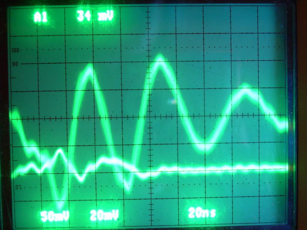
        The same settings used on the Tektronix TDS 3054C in POST 2234 I used on my Tektronix 2445A and this is what I got ......


        It ran for about 2 Hours at 12.45 VDC steady with my cheap meter didn't go up or down for this test run ..... and no heat ??? Is this why theres no "Heat" terminology in the title of this circuit or did I do something wrong ??

        @ Jibbguy , it was hard to find anything quickly and without Aarons potentiometers presets my Scope speed at 150Mhz you can loose traces quick

        @ Harvey, I was so confused, I need to read all the posts carefully sometimes I get in a hurry with a little tunnel vision thrown in

        Glen
        Open Source Experimentalist
        Open Source Research and Development

        Comment


        • Hi Fuzzy,

          Heat does appear for me mostly latest after 10 Minutes,
          and i am not sure, if you can use the same Values from the Quatum Article for all Parts,
          or only for the one, what is used at this Setup there.
          When i adjust my circuit, i mostly do it with my Meter, i set a low duty Cycle,
          then turn the Gatepot to the Border, where it shows at the Scope the best Value,
          and then i change the Frequency, till Voltage at the Source is nice.

          What i have tried with other Coils is, to find her 'Resonance', and what i have seen,
          it is allways different, depends at the Wires and the Resistance.
          For me, there is any Element different, and need other Settings, as the one from the Quantumarticle,
          so far, i dont have the exactly same Parts.
          The heat comes mainly, when i get Spikes at the Circuit, just with a Waveform it isnt that good.
          Maybe you try to change the Gatepot to the best Value, when you have the Ringdown,
          and then change the Frequency at the Timer. Its true, its first some fiddling around.
          Theorizer are like High Voltage. A lot hot Air with no Power behind but they are the dead of applied Work and Ideas.

          Comment


          • Hi Joit. Am delighted to see that you're also testing our circuit? I never mentioned it but was intrigued with the resistor that you wound without a 'frame' of sorts. It seemed so innovative. I always looked to find thick wire on the resistors. I actually think it's all that's needed. So chuffed you're also doing this test.

            Comment


            • What happened to the original RA circuit and its testing

              Why is everyone deviating from the original circuit and tests?

              Has the COP=17 claim already been proved/disproved?

              .99

              Comment


              • Aaron,

                1) What is your final conclusion as to where your "aperiodic oscillation" is coming from, the 555 or the MOSFET or the combination?

                2) Can you get this oscillation at the 555 without the MOSFET connected?

                3) Why do you need to use a current limiting resistor in the 555 supply? What happens when you remove this resistor?

                4) Have you concluded testing on the original RA circuit?

                5) What is your goal in general, since it seems to be changing and now not what you had originally indicated.

                .99

                Comment


                • For those that missed it, the 5.4MHz noise frequency scope shot is in the recent pdf.

                  Also, it is clear that the scope is mis-calculating the frequency of the wave forms shown. The channel 2 frequency displayed on the scope in the shot on page 4 reads 1.493MHz while in reality the true frequency of the wave form is about 416kHz. "Low signal amplitude" displayed on almost all the scope shots showing frequency most likely explains the reason for the error.

                  .99
                  Last edited by poynt99; 08-29-2009, 06:03 PM.

                  Comment


                  • @Glen

                    Hi Glen,

                    The purpose of me using the fractional watts power range was to find the negative zone so I could get the net negative wattage. With that setup, I only had heat on the mosfet, 555 chip, and 555 power pot.

                    So it wasn't really intended to produce heat at the load and in this condition, I found the load went up to 1.1C below ambient.

                    But, if heat is the goal for the load, I would still recommend using small, small power. The reason is that it is so much easier to see the gains on smaller power than big. Going up in power can still have gains, just the big spread is harder to achieve with higher power.

                    Then after getting some gain at the small power levels, then move up. It would have saved me a lot of time if I started at the lower power levels.

                    And with the schematic I most recently posted, the only real difference between the original circuit is that I have a pot meter for the power of the 555. That is it.

                    Your shunt waveform looks pretty balanced on top and bottom but it says 34mv, is that the dc average it is showing? Just to see if you can get heat, you could open up the on time until it is about 100mv and let it run a bit just so you can sense some heat - so at least you know the circuit is running right. The wave forms sure look like it.
                    Sincerely,
                    Aaron Murakami

                    Books & Videos https://emediapress.com
                    Conference http://energyscienceconference.com
                    RPX & MWO http://vril.io

                    Comment


                    • @poynt

                      Originally posted by poynt99 View Post
                      What happened to the original RA circuit and its testing

                      Why is everyone deviating from the original circuit and tests?

                      Has the COP=17 claim already been proved/disproved?

                      .99
                      I wouldn't assume "everyone" is deviating from anything. Your own personal experiment is the only that will have the most value to you.

                      Whether or not heat is produced is one issue. At any power value, it will forever be in debate as to how much the heat is worth for the power input.

                      With showing a negative net wattage on circuit, with cooling at load and heat at switching components, ANY heat at all is automatic free energy. I believe you and your peers may be at a loss to describe what is happening with conventional electron current model theories - but you're welcome to try.

                      My goal is to show clear evidence of unconventional behavior in the circuit that defeats either unity, conventional closed system thermodynamics, inductive laws, electron current theory, etc... and I believe it has clearly been shown that there are very unconventional things happening - that are not included in your models or beliefs but is completely consistent with everything Rosemary, myself and others have been saying for a long time.

                      I have done draw down tests and have beat the control draw with the Ainslie circuit. That is over 1.0 COP with heat production compared to the equivalent wattage needed to get the resistor to the same heat from a control dc supply. I may post these results at some point but for now, you are stuck to explain away what has already been shown.

                      Positive heat on switching components and even if I throw out the cooling of the load as an anomaly if it is up to only 1.1C below ambient (and weighs close to 1 pound of total mass on the load resistor) - the 555 and 555 power pot was up to 10C above ambient with net negative wattage being drawn as indicated by the data.

                      Was that whole demo simply done wrong? Would you claim the Tektronix TDS3054C is erroneously collecting data? Does Ohms Law fail in giving accurate current measurements based on the voltage drop across the current sensing resistor? Is Excel giving false calculations on the THOUSANDS of real time samples to determine the average per waveform draw?

                      Even if I never post another thing in this thread, I honestly think you have no honest explanation for any of it.

                      The negative wattage net draw test shows any work that is done under those circumstances is all free. This is simply an example of the circuit out of equilibrium with it's environment so that work can be done from free environmental potential that enters the circuit. Is it from RF, vacuum energy, zipons, etc...? Irrelevant in the point that the system is getting energy from somewhere and if it isn't from the battery, then that is very clear evidence that there is energy entering from the outside - it is NOT a closed system, therefore, conventional closed system equilibrium thermodynamics do not even apply.

                      In either case, I'm going to focus on making heat now because that can be done without the Tektronix if it is in drawdown tests. And if I have to return this Tektronix in a few days, then at least I can carry on. Much nicer with it since tuning and finding what I want is a breeze with it, in either case, the data collected on the waveforms I showed in the negative range is pretty valuable and with a net negative wattage, that is more important to me to have the data on that rather than positive wattage waveforms.

                      Science is slow and takes a lot of hours. Simply putting together a circut and immediately debunking it while simultaneously admitting "no need to understand the nature of the energy" - is NOT science but that is all I have seen from your side of the camp. In my opinion, it IS the understanding of the nature of the energy that allows one to make progress here because without that understanding, the things that I have found would never even be looked for.

                      If I did these experiments from the conventional mindset, I would have failed miserably because possibilities are already ruled out and that would have prevented me from even asking the questions.
                      Sincerely,
                      Aaron Murakami

                      Books & Videos https://emediapress.com
                      Conference http://energyscienceconference.com
                      RPX & MWO http://vril.io

                      Comment


                      • @all

                        I'm deeply grateful to Peter Lindemann for introducing me to Rosemary's circuit, to Rosemary Ainslie for the brilliant foundations that she has laid out to everyone and the endless support in the experiments and to Tektronix for so kindly lending me the TDS3054C! It makes such a huge difference having the right tools.

                        I hope that everyone in this free energy field that is interested in hard core analysis of their devices would take up this Detailed Integrated Power Analysis method of reading the power draw on their circuits because of the accuracy. I can clearly see this should be a new standard for this field. I learned it from Rosemary and she learned from the best.

                        This Tektronix does 10,000 samples per screen per channel. The Fluke 123 Scopemeter does about 1500 or so, 6~7 times less so it is obvious the accuracy in high sample rates. Anyway, I think there are many people that have scopes that at least have some data logging ability and this method can still be used for thier own sample rate and would be more accurate than the reading on the screen of the scope.

                        Again, I'll be working on some heat production experiments from here on and will post as I have time. I have taken so much time in the last 8 weeks or so on these projects and have to catch up with normal life for a bit. I'm excited to see everyone's replications.

                        Anyway, I'll be posting more in time and will do what I can to help replicators with tuning.
                        Sincerely,
                        Aaron Murakami

                        Books & Videos https://emediapress.com
                        Conference http://energyscienceconference.com
                        RPX & MWO http://vril.io

                        Comment


                        • @poynt

                          Originally posted by poynt99 View Post
                          For those that missed it, the 5.4MHz noise frequency scope shot is in the recent pdf.

                          Also, it is clear that the scope is mis-calculating the frequency of the wave forms shown. The channel 2 frequency displayed on the scope in the shot on page 4 reads 1.493MHz while in reality the true frequency of the wave form is about 416kHz. "Low signal amplitude" displayed on almost all the scope shots showing frequency most likely explains the reason for the error.

                          .99
                          The frequency reading is 100% irrelevant to the accurate data collection of wattage readings on the shunt.

                          You also on many occasions seem to ignore the fact that the 555 timer settings are overridden on any oscillation. If the timer circuit is set at 416kHz, the oscillation can run much, much faster. You need to do the experiments before simply speculating on what you believe is right. Do the experiments and at least you have a rational basis for your beliefs.
                          Sincerely,
                          Aaron Murakami

                          Books & Videos https://emediapress.com
                          Conference http://energyscienceconference.com
                          RPX & MWO http://vril.io

                          Comment


                          • Originally posted by Aaron View Post
                            Hi Glen,

                            The purpose of me using the fractional watts power range was to find the negative zone so I could get the net negative wattage. With that setup, I only had heat on the mosfet, 555 chip, and 555 power pot.

                            So it wasn't really intended to produce heat at the load and in this condition, I found the load went up to 1.1C below ambient.

                            But, if heat is the goal for the load, I would still recommend using small, small power. The reason is that it is so much easier to see the gains on smaller power than big. Going up in power can still have gains, just the big spread is harder to achieve with higher power.

                            Then after getting some gain at the small power levels, then move up. It would have saved me a lot of time if I started at the lower power levels.

                            And with the schematic I most recently posted, the only real difference between the original circuit is that I have a pot meter for the power of the 555. That is it.

                            Your shunt waveform looks pretty balanced on top and bottom but it says 34mv, is that the dc average it is showing? Just to see if you can get heat, you could open up the on time until it is about 100mv and let it run a bit just so you can sense some heat - so at least you know the circuit is running right. The wave forms sure look like it.
                            Hi Aaron,

                            The numerical at the top of the scope screen is the "Trigger Source" A1 and the "Trigger Level" 34mv the wave forms at 50 ns is really cool looking a kind of spiral oscillating wave I'll try to get a better photo of a lowered screen intensity.

                            I'll have more time to fool with the potentiometers adjustments, but with the sampling rate my scope has it's real slow ...... kinda like a hide and seek game. The best part is I thought there was heat going on like in the "Rosemary Anislie COP>17 Heater Circuit" but this circuit with the minor alterations does something different and I could not detect heat on anything at the potentiometers preset levels I show and are referenced in the PDF Ainslie-Murakami Negative Dominant Waveform Generator


                            One thing for sure this circuit makes some complicated and beautiful wave forms with minor component adjustments.

                            Glen
                            Open Source Experimentalist
                            Open Source Research and Development

                            Comment


                            • @Glen & heat

                              Hi Glen,

                              With your setup, are you able to detect heat on the pot between battery + and 555? And what about the 555 chip and mosfet? Do you have some kind of IR thermometer you can aim at those to see if there is heat?
                              Sincerely,
                              Aaron Murakami

                              Books & Videos https://emediapress.com
                              Conference http://energyscienceconference.com
                              RPX & MWO http://vril.io

                              Comment


                              • Originally posted by Aaron View Post
                                Hi Glen,

                                With your setup, are you able to detect heat on the pot between battery + and 555? And what about the 555 chip and mosfet? Do you have some kind of IR thermometer you can aim at those to see if there is heat?
                                Hi Aaron,
                                I don't have a IR thermometer was going by touch only ..... with the "Rosemary Anislie COP>17 Heater Circuit" at certain levels the Mosfet heat sink and 10 ohm resistor you could'nt hang on to way to hot , every thing on this circuit was cold but the scope showed it was working ...... it through me a little there.

                                I'm going to see if i can get a IR detector wanted one anyway for my work

                                Glen
                                Open Source Experimentalist
                                Open Source Research and Development

                                Comment

                                Working...
                                X