Announcement

Collapse
No announcement yet.

COP 17 Heater | Rosemary Ainslie

Collapse
This topic is closed.
X
This is a sticky topic.
X
X
 
  • Filter
  • Time
  • Show
Clear All
new posts

  • Hi Rosemary, actually the self oscillations were with air-core coils and some with cores when removing power from 555. Though I'm sure certain inductive heating elements would do the same as Aaron is showing.
    peace love light
    Tyson

    Comment


    • @poynt

      Poynt,

      The document that I put out on the negative wattage net "draw" from the battery - well, that answered the first few questions already but you asked anyway. If you want to hound me with questions and expect me to answer you, there are a few things that you might want to consider.

      First, you may want to actually do me the courtesy of reading it. If you did, some of your questions would have already been answered. Respect my time please, especially if you're skeptical about what this is. That is the whole point to the document. I don't mind helping you out with your questions but I think you get my point.

      Second of all, you should try to comprehend what I'm saying instead of figuring out ways that my way is wrong as you attempt to chisel it down until it is something that fits in your very own personal round hole.

      I heard that you're a genius if you can hold two opposing opinions firmly in mind at the same time, equally. What have you got to lose? See it my way and forget about what you know. Just try that for a while...like 90 days and see what your observations are like. You might find that some things start to make more sense or maybe not.

      Then at that point, if you completely disagree, can't you as a rational human being simply choose or more likely decide to simply go back to believing what you already believe? Sure you can. Just try it for fun and see what happens. I'm sure you have enough control over you mind to do that without getting emotionally riled up about it can't you? You should be able at will to simply BE the very essence of the opposing argument so that you can grok it. Not just logically rationalizing it in your mind based on your own already pre-conceived filters but actually BE the essence of the opposition with every fiber of your being. That would be science wouldn't it? Actually experiencing the opposing view in an argument as opposed to simply trying to make everything fit into your own personal viewpoint? Anyway, just a friendly suggestion.

      If you did the first and second, the reading and comprehension part, you would spend less of my time AND YOURS in dealing with things that have ALREADY BEEN ANSWERED. My time is valuable to me and I'm sure yours is to you.

      When something is tuned, changing the impedance of its flow will disrupt the tuning and that is exactly what series meters will do! Plus they absorb potential away from the circuit the same way that placing our hand on the resistor or mosfet can dampen the waveforms...we're absorbing potential like a capacitor away from the circuit.

      It will take simple paths to ground themselves into equilibrium and that is what we provide in relation to the circuit as do meters. Machines do the same thing. Meters I'm talking about, even these scopes. They call it SAMPLING for a reason...it takes a sample from your circuit.

      They all take away from radiant charging effects. Disconnect them when not in use! Your efforts will increase. Only connect them fresh each time you want to measure something and let them sit for a minute to get their bearings straight.

      We've heard the last of the recommendations that aim to squash the gains...stop trying to push that agenda because that isn't happening.

      The meter will not show a negative current on a digital meter. It will be at 0.000 and will alternate back and forth between that and -0.000 with a negative sign in front of it, but it won't show a negative current value. It will show a negative voltage and I hope you know the difference enough to know that because it does show negative voltage, that doesn't mean they'll show a negative current value - just 0's.

      I've already done that and it does exactly what I just told you it shows. 0.000 or -0.000 back and forth, that's it. No positive amperage indicated. That means it is definitely 0.000 amps or less. In either case, that would indicate cop 1.0 or cop 1.0+ and since there is no measurable positive current it cannot be less than cop of 1.0... according to the data presented. Is it over 1.0 COP? Yes, I think so.

      There was for example 1 degree different in load from ambient. Up to 10C on the 555 power pot. 8C on 555 itself. 1-2 on mosfet. How much wattage would you ballpart that would be?

      More than what the meter would show. The most decimals it shows is 0.000 so at bare minimum it would show 0.001. 1/1000 of an amp! At about 12v. That is 0.012 watts.

      1. Can a timer run on 0.012 watts?
      2. Can that 1k 10 turn pot get to 10C over ambient on 0.012 watts?
      3. Can the 555 timer produce 8C over ambient with 0.012 watts at the same time as the pot at 10C over ambient?
      4. can the mosfet be 1-2C above ambient?

      What about this:
      • timer minimum power needed?
      • power needed to warm 10 turn 1k pot to 10C over ambient?
      • 555 timer chip heat 8C over ambient - how much to do that?
      • watts needed to maintain mosfet 1-2C above ambient?
      • watts needed to maintain load a 1C difference from ambient?
      Can all 5 of those be accomplished with 0.012 watts at minimum?

      If they can be, then it is doing that work without that much being able to register and at 0.000 or -0.000 on the amp meters indicate unity or over. That itself is over 1.0 COP. These meters aren't broken. I hooked an led up to the battery with resistor in series just to see if the amp meter function worked and it worked just fine. Had 0.017 amps. That is more than 0.200 watts!!

      Are you telling me that all that work is done for almost 1/16th of what that one single LED was running on? 1/16th of what it takes to run a 0.2w led or less than 1/16th of that appears to be running a mosfet, 555 timer and heating both AND raising a 10 turn 1k pot to 10C above ambient.

      Wow, 0.2 watts divided by the minimum measurable amps that in reality was too low for the meter to show is 0.012 watts. 0.2 divided by 0.012 is 16.67 times.

      So again, 16.67 times less than what it takes to run a led at 0.2 watts is making this:

      mosfet run and be at 1-2c above ambient
      555 timer run and be up to 8C above ambient
      timer power pot heat up to 10C above ambient
      load that weights about 1 pound is held at 1C from ambient
      shunt resistor that weights about 4 ounces is held at 1C from ambient

      So, all of that is done with 16.67 times less power than it takes to run a 200mw led.


      I say 0.012 minimum of course because at minimum positive current that it can show, it would be 0.001 amps * battery = 0.012 watts. Do you understand? It is fluctuating between a possible 0.00099999999999999999+ amps and under and the meter rounds down or something. It ceratinly isn't rounding up so it is going between that much wattage and less.

      Again, one particular led neeed 0.017 amps but this circuit is using less than 0.001 from the same power source, yet it... again....
      • timer minimum power needed?
      • power needed to warm 10 turn 1k pot to 10C over ambient?
      • 555 timer chip heat 8C over ambient - how much to do that?
      • watts needed to maintain mosfet 1-2C above ambient?
      • watts needed to maintain load a 1C difference from ambient?
      Can that be done at 12v and with less than 0.001 amps? If so, then it is possible that it is still positive wattage ONLY ACCORDING TO THE FLAWED TEST OF USING A AMP METER IN SERIES. And even if it is positive, again, can it be done with 12v and less than 0.001 amps? Answer the question, just ballpark it.

      But again, that is a flawed way to read the current at those frequencies. THAT IS WHY YOU USE SOMETHING THAT CAN TAKE 10,000 SAMPLES OVER A VERY SHORT PERIOD OF TIME! Unvelievable!

      Was it proven by anything I did? Everyone has to decide for themselves.

      I'm open to the possibility that there are measurement errors.

      If current is no able to be accurately measured by the voltage drops over a resistor, then say so because I really want to know!

      If that is an accurate way to measure current according to Ohms Law, then the measurements appear to be correct. However, you obviously have a problem with this. If that is not an accurate way to measure current according to Ohm's law, then the measurements are incorrect. Are you suggesting Ohm's Law is wrong?
      Sincerely,
      Aaron Murakami

      Books & Videos https://emediapress.com
      Conference http://energyscienceconference.com
      RPX & MWO http://vril.io

      Comment


      • Originally posted by FuzzyTomCat View Post
        Hi Aaron,

        I went to Harbor Freight and picked up the Non-Contact Infrared Thermometer - Harbor Freight Tools - Quality Tools at the Lowest Prices and I found my Fluke 87 DMM for some good DC voltage readings.

        I think I'm going to do the same 2 hour test and use one 12 volt 3 Ah battery instead of the (2) 12 Volt 4.5 Ah battery's I used yesterday in my trial run with all the same parameters in the PDF and scope shots taken but this time with the Non-Contact Infrared Thermometer and DMM readings, then well go from there !! I'm going to start around 9:00 PDT or about 1 hour from now if you, Rosemary or anyone else may have comments (NO comments please poynt99 for now) on this go round, on a closest apples to apples test .....

        Glen
        Fuzzy. I'm so sorry I've taken so long to answer this. Yesterday and today I've been falling asleep at the drop of a hat. Before that I was so keyed up I couldn't sleep when I tried. Perhaps this old body is trying to 'catch up' here. Yet again missed this post and I see that you're no longer there. Hopefully you'll see this when you wake up.

        In any event. I'm just so chuffed that you're replicating here. Really, really honoured. Always knew there was some considerable intellect and talent behind those glasses. You've romped into the waveforms with such ridiculous dexterity. I'm only sorry to see that you've moved yourself off the board. I think you should stay right there. Just to keep close watch on the data. Many many thanks Fuzzy.

        Regarding the results. You appear to have all the symmetries that Aaron found but not at the same voltage values and therefore not at the same benefits? We'll need your's and Harvey's input here to discuss this. And we'll also need to see your use of that new IR number.

        I said it earlier but would like to re-iterate. We are really honoured to have yours and Harvey's talents involved in replicating. It makes such a difference. Really nice efforts from a really cool kitty. And at the risk of boring you - yet again, thank you.

        Comment


        • Originally posted by witsend View Post
          I find this a encouraging. Had no idea of this negative voltage effect. In which case - is the 'heat' dissipated at the resistor only evident if the net value of the voltage across the resistor is above zero? And is the heat then also the difference between the two values above and below zero? And then the next question. Does the negative voltage over the resistor constitute a potential recharge to the battery? .
          I'm still waiting for some opinions to this question. To my opinion, the cooling effect and the battery recharge is two different things, but let's hear all opinions.

          Comment


          • The PCBs has finally arrived

            Hi Group,

            The Rosemary Ainslie Switch Circuit PCBs has arrived and I will be
            shipping 20 pcs. to GOTOLUC on Monday.


            If you want a PCB for yourself then please PM GOTOLUC and he will
            send you one. It may take approximately one week for the PCBs in
            shipping time from Norway to the US.

            I can see from this thread on page 1 that there is a
            small change in some resistor values. This will have NO impact on
            the PCB itself. The layout is still correct. Just ignore the printed
            values on the PCB and solder in the new resistor and capacitor values
            so that you get the correct frequency and duty cycle. If you don't want to
            use the trimmer resistors then just solder wires from the PCB to external
            variable resistors.

            I will be soldering one unit next weekend and start testing.

            Regards,
            Groundloop

            Comment


            • Groundloop - many thanks indeed for the circuit. Am blown away. it just looks so professional. If you're also experimenting - would love to see results posted here.

              Many thanks indeed for this.

              Rosemary

              Comment


              • Rosemary,

                Thanks you for the nice words. :-)

                Yes, I have ordered some parts and will solder one unit next weekend.
                Will start testing then. Small steps........

                Regards,
                Groundloop.

                Comment


                • Hi everyone,

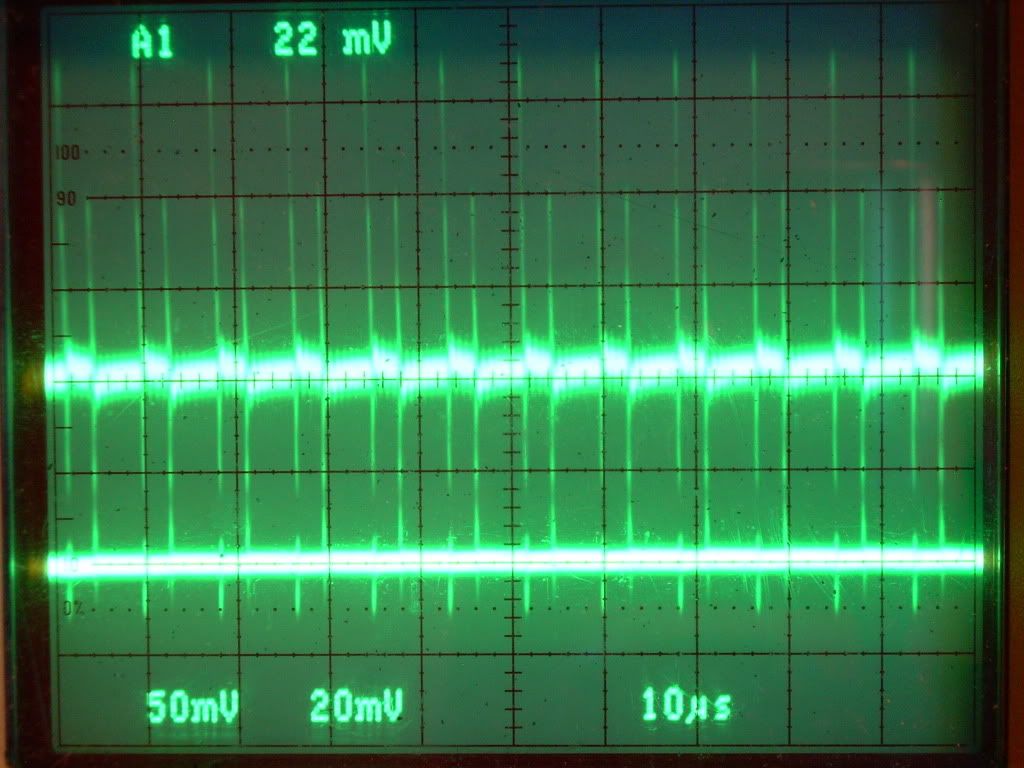
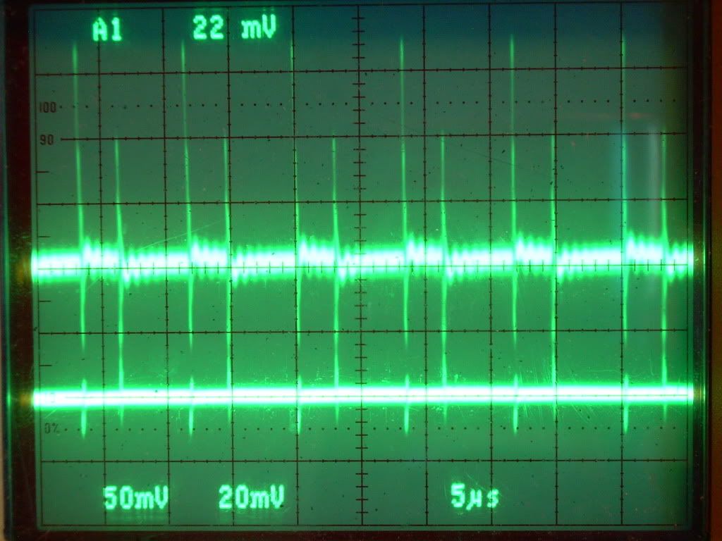
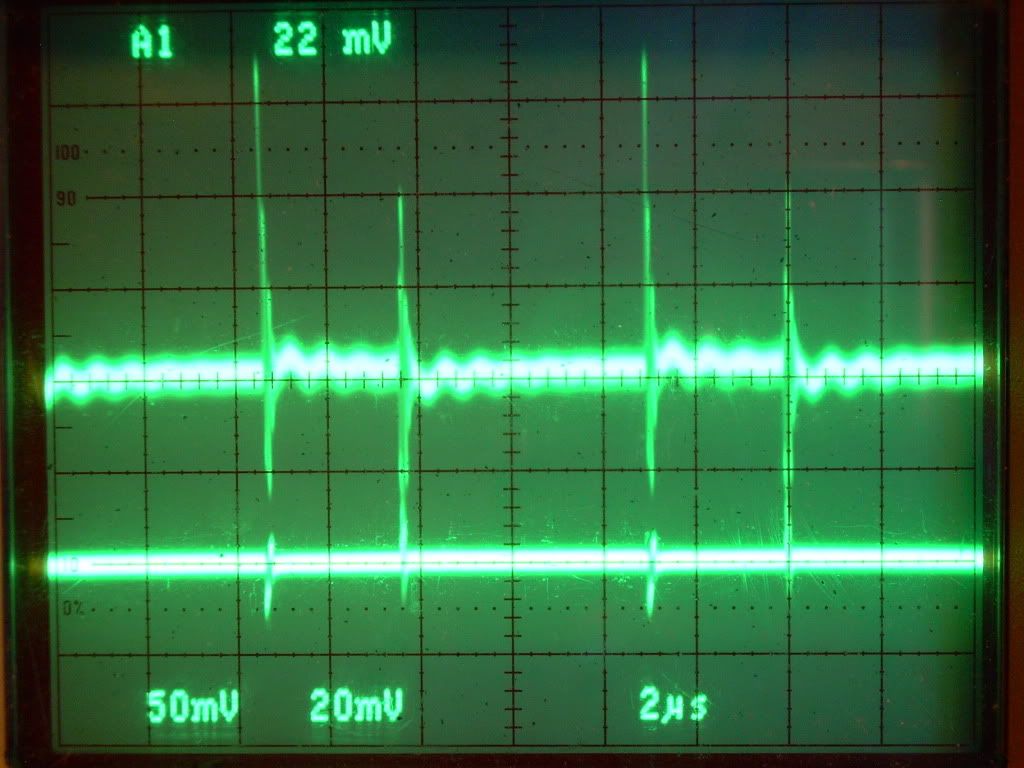
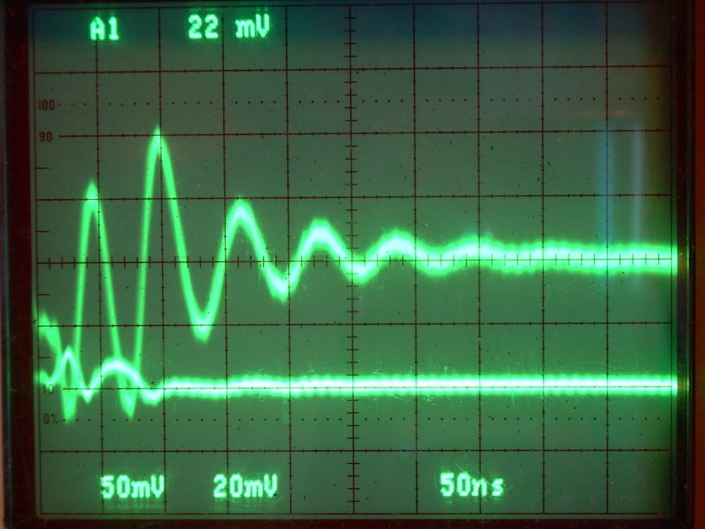
                  I'm still compiling the data on my battery draw down and temperature testing of the components. I disconnected the potentiometers and did the presets to insure they had the correct figures using my Fluke 87 and there was some difference from my RCC DMM. I made some new scope shots with the intensity turned down so the wave forms are more visible the trigger level is at 22mV this time maybe due to the more accurate potentiometer settings, I'll be posting my testing data tomorrow.


                  Glen
                  Open Source Experimentalist
                  Open Source Research and Development

                  Comment


                  • Aaron,

                    I appreciate the time you take to answer my questions.

                    I am quite willing to consider the possibility that a circuit or device might exhibit strange behaviour, even OU behaviour. That's one reason why I partake in these forums.

                    However, before I decide to invest any time and effort on something, it's only logical to investigate the phenomenon fully to the best of one's abilities in an attempt to explain what is observed by conventional means. This is what I am trying to do with my questions regarding your observations and scope shots.

                    I am suggesting that one thing at a time be examined, and one of the easiest would be the direction of the current. So for the time being, the powers and heating issue is on hold for me.

                    Now, about the DC ammeter. I do not understand the aversion being expressed here.

                    The DC ammeter will not alter the results any more than the shunts presently in the circuit will. There is a current sense resistor (shunt) inside the meter that does the same thing. Any averaging that is done by the meter is done after the sampling, so it has no effect on the current itself.

                    The other important point is regarding the meter resolution. I am assuming when you tried it you were using the AMPS input rather than the milliAMPS input? Most meters have a 200mA FS input and a 10A FS input. I am assuming you used the 10A input? If so, that is not correct. Try again but this time use the 200mA full scale input. Surely there is at least 1mA being used in this circuit, and if so it should be indicated with ease, and of course the direction will be also. By using the 10A input, it's no wonder you saw no current reading.

                    .99

                    Comment


                    • Hi Poynt. Glad to see you're still considering all options. As Aaron isn't on line yet - I think I can answer you here. He has tested the amperage on three different meters including the Fluke 123. All three register 0 volts or -0 . The Fluke doesn't have that 10amp setting.

                      EDIT - am answering you here Poynt as I feel I'm monopolosing posts. Hopefully you'll see this. I believe that Aaron has done this. But he'll have to answer you himself.
                      Last edited by witsend; 08-30-2009, 12:47 PM. Reason: answer to poynt -

                      Comment


                      • An alternative if you are not open to placing a DC mili-ammeter in the circuit, is use a conventional DMM meter (not a scopemeter) set on DC Volts (set on 200mV if not auto-ranging) across the present shunt.

                        The meter will average out the positive and negative excursions and indicate a net direction of current.

                        .99

                        Comment


                        • OK we go over it again...

                          This is the problem: DMM's, and even bench multi-meters, are known to not accurately measure such fast non-sinusoidal and non-repetitive waveforms... Even if they have "True RMS" written on them.

                          Since this problem is fairly well known and often used as a favorite debunking argument, presumably you must know this yourself, so it is odd to hear you requesting it.

                          The reason they cannot accurately measure such "spiky" and non-repetitive waveforms is because internally, separate RMS circuitry is used... This RMS circuit physically conditions the signal before sending it to the A-to-D and display. The circuit has limitations in F Response; and some assumptions are made within its design for expecting repetitive signals, which are then not always true for non-repetitive. And when in RMS mode (the only DMM mode that could hope to meaningfully read any of these signals except the "Temps"), the result is always "positive"... There is no such thing as "negative RMS". And of course if left set to "DC" you would get meaningless constantly changing numbers and polarity... Wholly dependent on the display's update rate.

                          Sometimes in a well-balanced and stable circuit, you can "cheat" and put a cap & resistor across the terminals of the DMM set to DC and get a poor man's "Averaging" effect just as a rough check, but any messing around like that WILL affect this circuit that is balanced "on the head of a pin" impedance-wise; and is out of the question here: As this is NOT a stable and "well balanced" circuit, BY DESIGN!

                          ...And this instability and extreme susceptibility to changes in impedance is also the reason why some detractors' yelling on the other forum for "using a capacitor instead of a battery" is absurd... the oscillation effect being studied in the first place would almost certainly be ruined by all that capacitance in the circuit (adding capacitance is the most common method for getting rid of "unwanted" astable oscillations in commercial electronics)... Lol that is what they want anyway; as those pesky little oscillations are obviously driving them crazy

                          And of course when trying to read current in-line with a DMM or analog Meter, voltage across an internal shunt resistor is used...So all the above restrictions apply. Analog panel Amp Meters that use inductance to move the needle are heavily reliant on operating within a frequency range... And would not be accurate in this case either.

                          Any Hall Effect Current Clamp-Ons i've ever seen have very serious restrictions in Frequency Responce... Way too slow here. The only way to accurately deduce current for this circuit is across a shunt; with either the scope to do the math on-board, or the math done on PC-stored raw samples. And that, as Aaron has pointed out, is how the Pro's do it (whether they use a digital storage oscilloscope, or a fast-sampling PC-based data acquisition system, the results would be exactly the same).

                          Scopes that have on-board measurement do not use an internal physical circuit to condition the AC signal into a flat "DC-like" representation before measuring it.... They use math to figure both Average and RMS based on the actual "raw" signal... By using calcs based on "area under the curve" that are computed in a rolling average. This is why they are the MOST reliable and accurate method in these situations.

                          This is exactly how Aaron has done it and we should applaud him for it

                          Comment


                          • Aaron,

                            Despite the above post, please try either the DMM milli-ammeter inserted in place of one of the shunts, or use a DMM meter set to DC Volts (or milli-volts) and measure the voltage across the shunt of your choice.

                            In either case the meter will average out the positive and negative excursions and give an indication of net current flow amplitude (if there is one) and direction. If the positive and negative current is equal, then the meter will read "0.000" indicating the average net current is zero.

                            .99

                            Comment


                            • Poynt - let's assume that Aaron does this and the results remain at 0.00 volts. What's the next test? What I'm actually asking is - 'at what point do you consider that the evidence may be consistent with an over unity result?'

                              Theoretically you could continue demanding a string of tests and then disclaim the evidence on the basis that you cannot 'yet' devise a new test? This would not be unlike TK's debunk. But he devised a string of tests without a single detailed power analysis and then concluded in his last post that he was 'convinced there was no overunity on the circuit' or words to that effect. Edit. I might add that not one of you classicists asked him to give a detailed account of a single test conducted. And how many videos did he do on this? Way too many. Where was your critical analysis then?

                              Jibbguy has suggested that there comes a time when mainstream's fractious objections become self-evidently obstructive and/or unreasonable. I wonder if you are not at the point yet. Aaron has obliged you on every required basis thus far. Why not oblige us for a change? I would love to know whether or not this waveform can be duplicated on your simulators? If not, it would be of very real interest. And even if so - it would be mind bending. How about it?
                              Rosemary

                              Edit. It reminds me of the sad parade of experiments that we conducted for academics. Every time a new test devised and every time we duplicated the experiment and passed the test. Notwithstanding which no single academic ever earnestly attempted his own replication nor would he make conclusive comment on our results. The organ grinder's monkey - dancing - but not even being paid in peanuts.
                              Last edited by witsend; 08-30-2009, 03:58 PM. Reason: another point

                              Comment


                              • Do the average current test as I have suggested using a DMM and the results shown by the Tek scope will either be supported or unsupported. If the latter is true then the results must be in question.

                                If the DMM reads "0.000" even on DC milli-amps or milli-volts, then either the net current is zero, or the meter's integrating A/D is too slow to provide enough signal to resolve. In either case, the meter reading would then have to be dismissed.

                                All we are looking for with this test is a solid "0.001" or "-0.001" (or better).

                                The goal is to provide a double-check against the scope reading.

                                .99

                                Comment

                                Working...
                                X