Originally posted by eternalightwithin
View Post
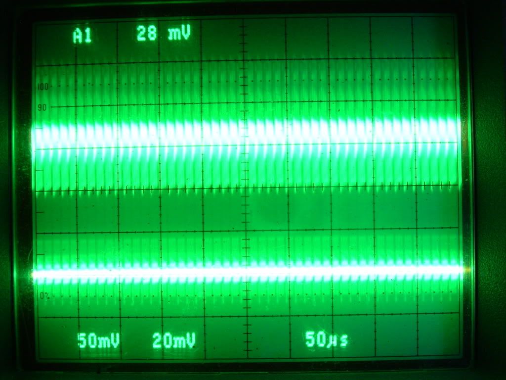
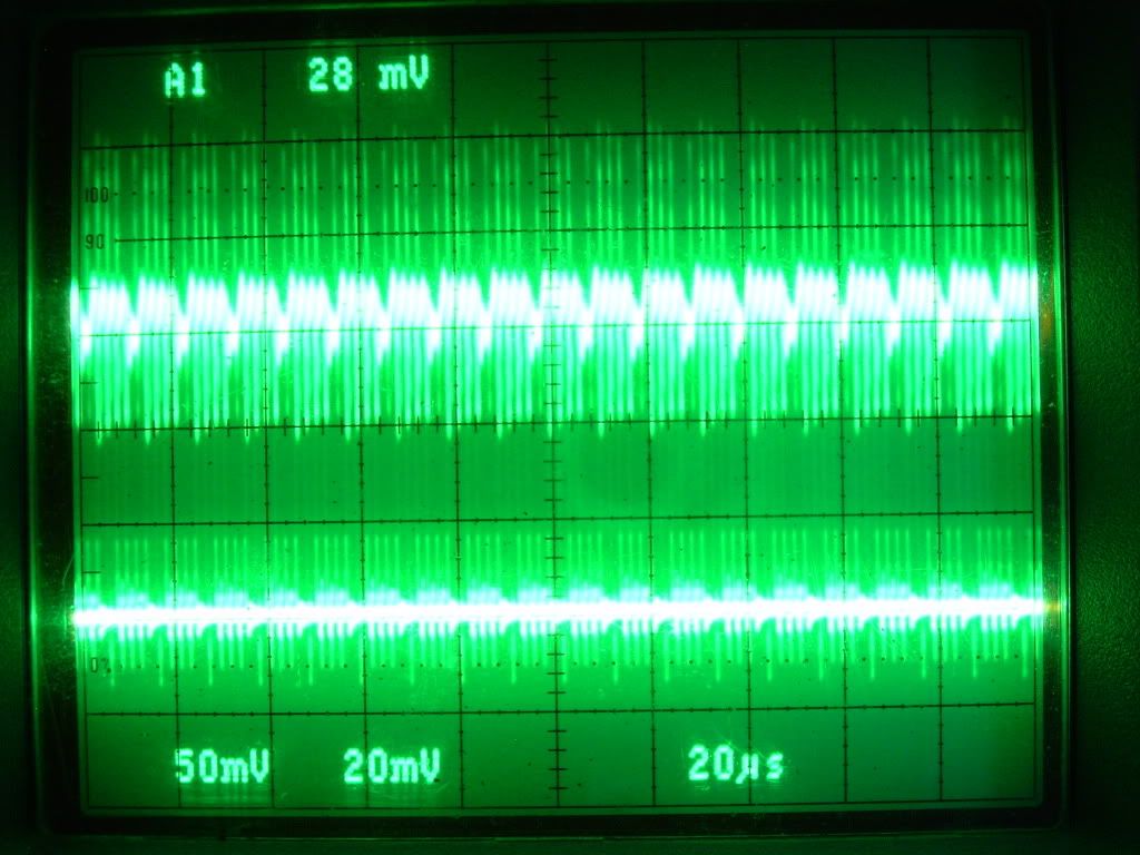
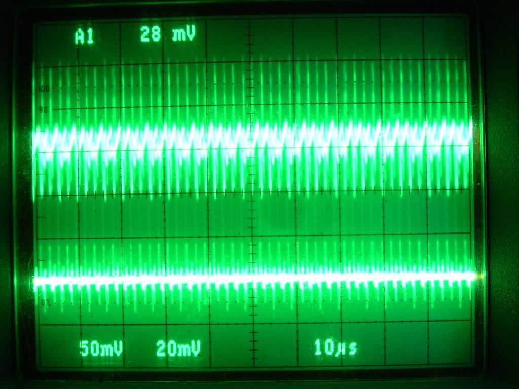
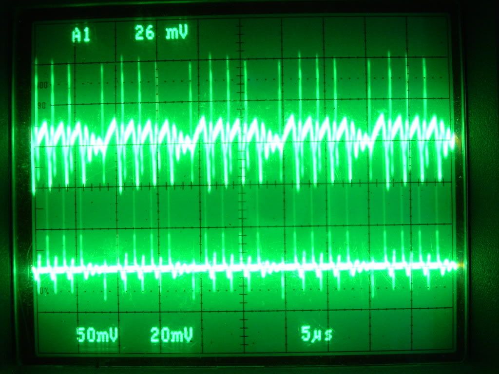
The problem with these approaches that have been suggested is phasing. The aperiodic operation is so efficient because it is driven by the inductor itself rather than the other way around. The controls are properly phased in harmonic synchronization even though they are firing on different harmonics throughout its range.
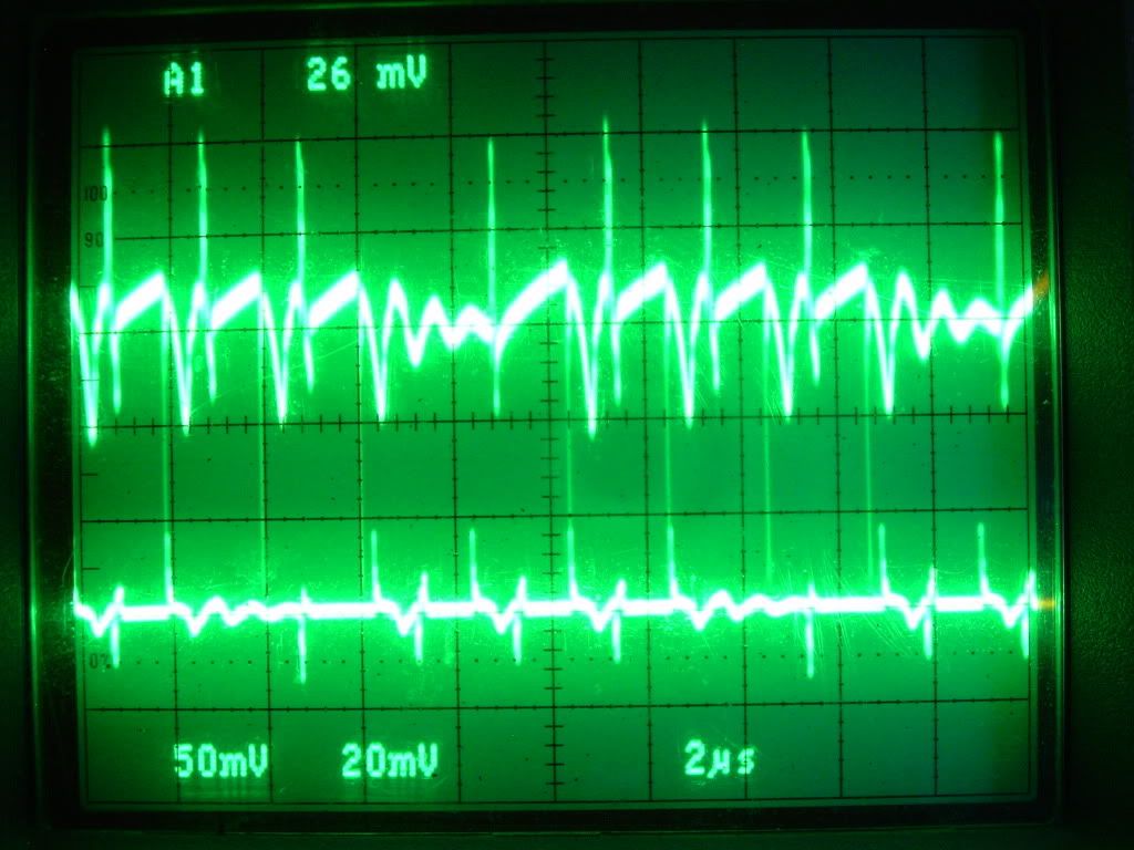
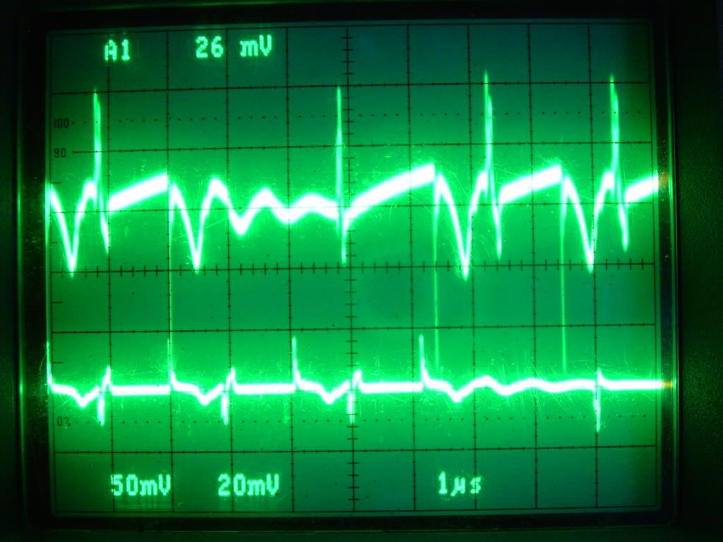
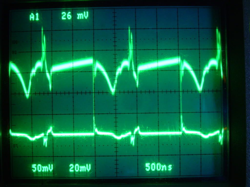
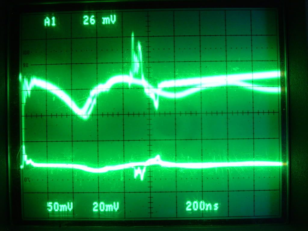
If I were to set out to eliminate the 555 from the circuit I would first have to identify how that feedback is occurring if I wish to duplicate it in the proper phase. As I have said before, this still has to be ascertained. I have even tried an inductive feedback into the timer to see if I could get it to sync up and allow the use of unloading the gate so badly. This action is a symbiotic reaction between the FET and the 555 and my tests last night hint that impedance is necessary on the return path to the battery.
If we knew specifically the fundamental resonant frequency of our load, we could then create a random pulse generator that selects any of the harmonics and fires a few pulses at that frequency. The pulse width can remain the same, it only needs to be as long as is necessary to charge the inductor. Then we could ensure nice clean steep FET operation at an aperiodic phase sync'd manner. But alas, the dynamics of the inductor change with temperature and other factors. It's resonant frequency shifts. So now we are getting into PLL resonant amplitude detection circuitry all of which we are adding in just to eliminate the 555. What is the old adage, if it works don't fix it? And KISS, keep it super simple?


 And it's not you who's the obsessive compulsive. It's me. I think the term is projection.

 It's easy to overlook things when your mind is made up and you don't want to be confused by the facts
  I really do admire his craftsmanship though

Comment