Announcement

Collapse
No announcement yet.

COP 17 Heater | Rosemary Ainslie

Collapse
This topic is closed.
X
This is a sticky topic.
X
X
 
  • Filter
  • Time
  • Show
Clear All
new posts

  • misc

    Originally posted by FuzzyTomCat View Post
    Adding a insulator between the Mosfet and the Heat Sink eliminating the antenna effect

    Starting voltage after purchase at store 2:30 pm PDT 12.67 volts, Start test after Mosfet Insulation between heat sink 7:30pm PDT 12.67 volts ........ Right Now 1:30 am PDT 12.69 volts after 6 HOURS ....... .02 volt increase above voltage at time of purchase ......
    Glen,

    I completely removed the mosfet from the heat sink and couldn't tell a difference so I put it back. At least, no difference with the settings I had running.

    Glad you and others have been getting different oscillating effects and that I'm not the only one. Also good to see that you have had an increase in some battery voltage while the circuit is running.

    Have you or anyone else seen that the pot adjustments to the mosfet are not linear and that there are non-linear zones where the waveform goes up then down then up or visa versa while turning the pots in the same direction? I'll show a vid on this because it is these areas that I have played in quite a bit.
    Sincerely,
    Aaron Murakami

    Books & Videos https://emediapress.com
    Conference http://energyscienceconference.com
    RPX & MWO http://vril.io

    Comment


    • HF Drive

      Here is my own attempt at my own suggestion of driving the original Ainslie circuit at 454.5kHz, in lieu of coaxing the 555 into its own wild oscillation mode.

      I see similarities to a scope shot I found of Aaron's on page 74 and posted it here. I am not certain of what he was scoping there, but I think it is the load shunt as well.

      Aaron's load resistor is resonating at a much higher frequency than mine (~5MHz compared to my ~1MHz). Also his shot indicates a second switching of the load about 800ns after each primary trigger of about 2.2us (base frequency of about 454.5kHz).

      I have not tried to implement this secondary trigger 800ns after each primary one, but the idea is there. A good approximation would be to drive the MOSFET at about 900kHz.

      .99

      Ref. Files are "HF_drive01.jpg" and "ainslie-murakami-dipa2-pic2.jpg"
      Attached Files

      Comment


      • Originally posted by eternalightwithin View Post
        I'm getting comfused now. Do we want electricaly conduction or isolation between IC and heatsink?
        Hi, what I did is place the mica between the Mosfet and the Heat Sink and put the white paste ( not the 99.9% Silver stuff ) on both sides of the mica and assembled ...... and that for some reason made all the difference in the world in getting "aperiodic oscillations" and quantity of them you can easily find and modify.

        The other thing is the battery the "Gel" type lead acid battery's don't work right you can find a "aperiodic oscillation" and it changes somehow and you end up chasing it with the "gate" potentiometer.

        The only issue I see now is how much of a loss is going out through the scope probe "ground" connections and not back to the battery negitive.

        Glen
        Open Source Experimentalist
        Open Source Research and Development

        Comment


        • .99 - That is closer to what I wanted to see, the 864µH version.

          There are few things I'd like to change up there. Reduce the drive pulse width to just a smidgen above saturation, just enough to give it some settling time. I'd like to see the first ring clipping time be as long or longer than the drive pulse.

          Then I would like to see the net power for B(-) and B(+) using the drain as the reference. I think spice will let you float the battery and ground the drain for scope reference, it will make things easier for the analysis if we are looking at those power curves already referenced to that point. I think the reason will become clearer later. We need to run the simulation for a bit as I suspect there will be a harmonic accumulation that you will see after a minute or so of running, if it is in resonance. You may want to sweep it to find the optimum resonant frequency, and then experiment with different sweep rates while using that as the fundamental center frequency of your sweep. We have not discovered the frequency's rate of change yet.

          The goal here is to show in the simulation how the battery will react to current flow into a circuit node that has a lower potential than both of its terminals and how that impacts the power readings for both terminals. This is why the more clipping we show with the body diode the better.

          Thanx again for your efforts here, it is appreciated.

          "Amy Pond, there is something you need to understand, and someday your life may depend on it: I am definitely a madman with a box." ~The Doctor

          Comment


          • Originally posted by Aaron View Post
            Hi Everyone - just back night before last from an incredible week hiking and sightseeing at Glacier National Park in Montana. INCREDIBLE - a much needed break! Will have to post pics later - WOW - talk about Majestic!

            Anyway, reading through posts and catching up on email.

            Welcome back - looking forward to the pics
            "Amy Pond, there is something you need to understand, and someday your life may depend on it: I am definitely a madman with a box." ~The Doctor

            Comment


            • WB Aaron, Hi Harvey , Poynt, Rosie Et all.

              I got Andrew (Other half of Panacea) to get the ball rolling, here is some data we got back so far from Aarons version, just gotta figure what we are doing wrong at this stage. More of a learned art more then a science .

              -------------

              Hey all,

              I built this circuit using Aaron Murakami's hand drawn 555 timer circuit (8/1/09) and have some results to report and interested in suggestions as to how to better capture the spikes off the resistor.

              The resistor I used was a 10 ohm 200W wirewound (RS Australia part# 169-950). They didn't have a 100W resistor but they sell as high as 1KW. Higher resistance values are available - does anyone advise against using a higher resistance or a variable wirewound resistor or experimenting with voltages?

              The attached photos outline the results so far. I can see the Mosfet self oscillation in the waveform (little resistance at gate - scope zoomed in).

              The temperature readings are as follows:
              Ambient temperature - 25C / 77F
              Resistor temperature - 53C / 127F (with air flowing in the room from a fan)

              One of the problems I had was I could only get 1.65V across the 470 ohm resistor which was connected across the 4700uF capacitor collecting the spikes off the resistor through a 1N4007 diode. I used an analogue volt meter to get the reading as the digital volt meter was jumping all over the place.
              Should I try a fast recovery, ultrafast, or schottky diode instead?

              The capacitor charged the most with no resistance to the gate, and highest frequency (both 100K potentiometers set to zero resistance leaving only the 2 x 1K resistors).

              The 555 timer was fed using a 9V regulator / capacitor, and a 3 - 15V 25A switchmode lab power supply set to 12V to power that. A 24V 4A switchmode power supply was used to power the resistor.

              Schemo used
              Imageshack - circuitschematicused

              Whole set up
              Imageshack - rimg00011

              500 ohms resistance at gate
              Imageshack - 500ohmsresistanceatgate

              little resistance at gate
              Imageshack - littleresistanceatgate

              little resistance at gate (scope zoomed in)
              Imageshack - littleresistanceatgates

              no resistance at gate
              Imageshack - noresistanceatgate

              Voltage spikes from the resistor
              Imageshack - rimg00071

              Thermometer
              Imageshack - thermometer

              Does anyone have any suggestions or questions?
              Andrew from Panacea

              Comment


              • Hi everyone,

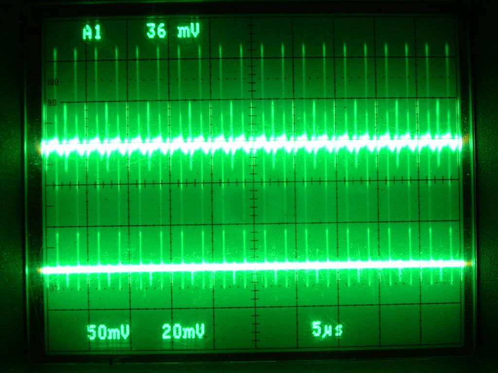
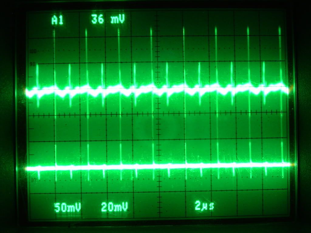
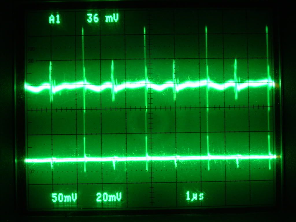
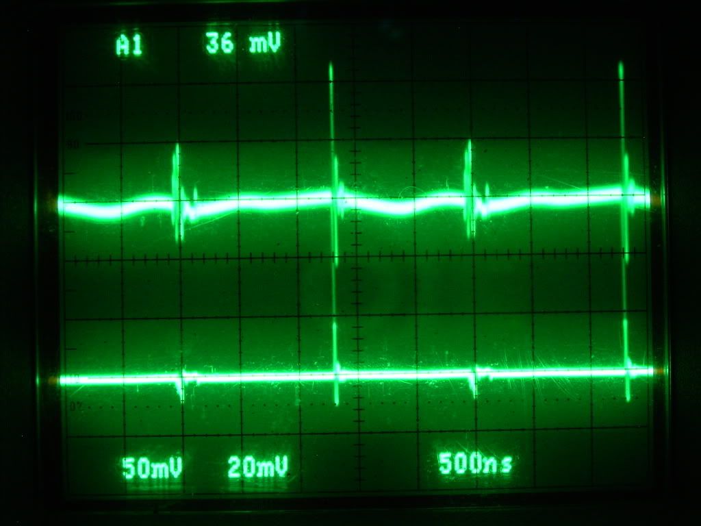
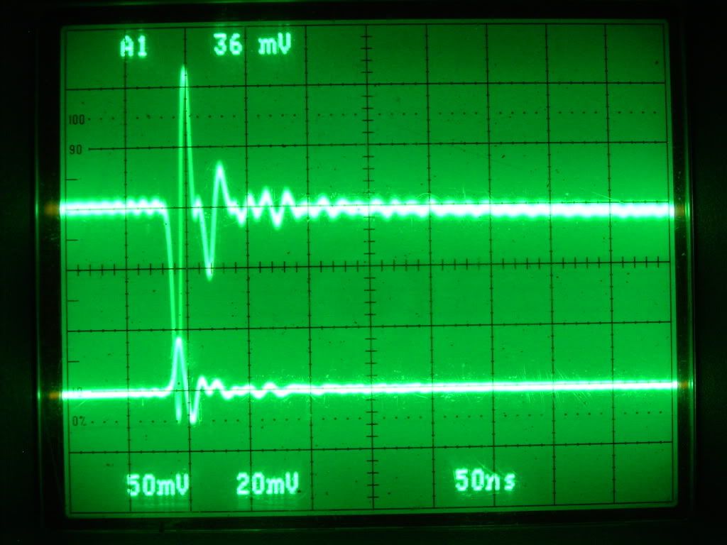
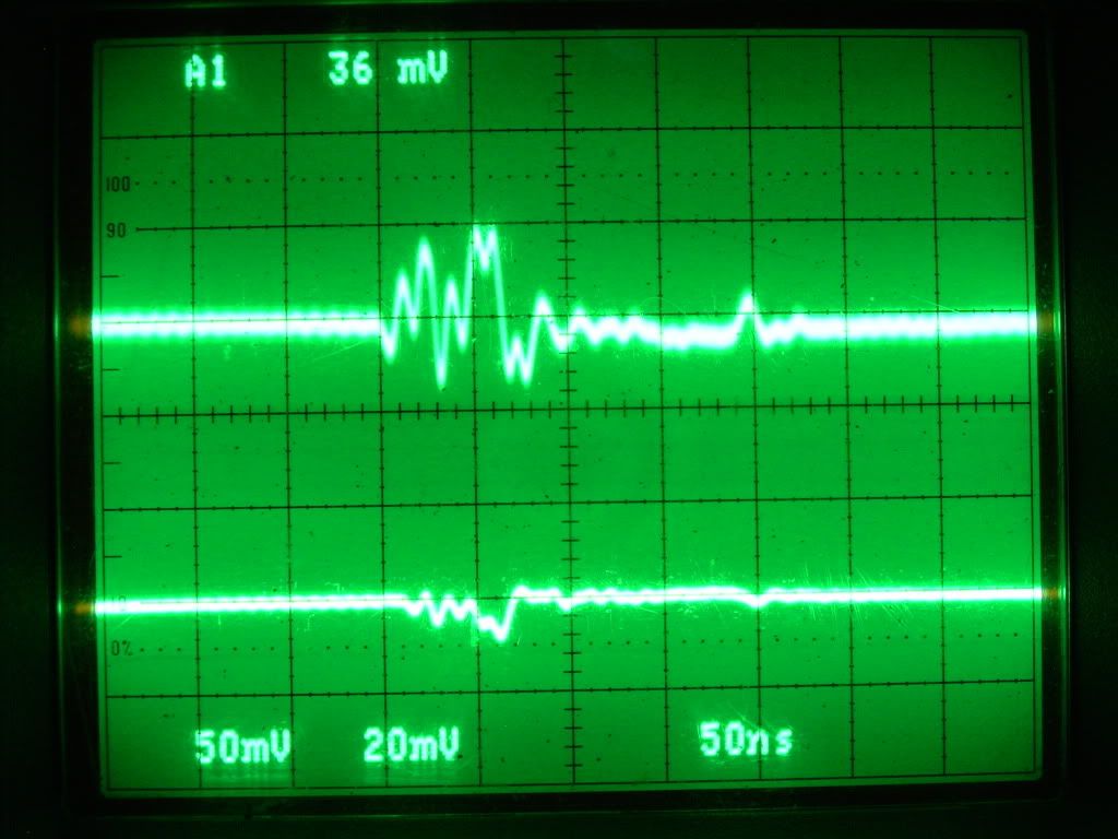
                After playing with the Gate potentiometer some more and possibly have achieved better results now, still using the "Ainslie-Murakami Negative Dominant Waveform Generator" circuit as shown in the PDF file .....

                Scope shots are DC coupled, probes at 1 ohm DC - X10

                Channel 1 is on the bottom [ A1 36mV ] ground is on battery negative side of a 0.24 ohm shunt and probe is at 555 negative rail side of shunt.

                Channel 2 is on the top [ coupled ] ground is on battery negative side of a 0.25 ohm shunt and probe is at mosfet source side of shunt.

                • Gate resistance: ? ohms ( 40 - 100 ohms estimated "test" still running )
                • On pot resistance: 32.8 ohms
                • Off pot resistance: 293.9 ohms
                • NE555N power adjustment pot resistance: 193.1 ohms

                COMPONENTS -

                1) Load Resistor 10 ohm Wire Wound , 100 watt , "MEMCOR" FR100 10 OHM

                2) Insulator between the Mosfet and the Heat Sink

                3) "Liquid" lead Acid battery
                Exide Technologies Model # GT-H
                TRACTOR - 12 aH
                CUTTING EDGE
                25 Reserve Capacity Minutes at 25 Amps
                Cold Cranking Amps 235
                12 Volt
                UPC Code: 017724265936
                Exide Technologies Exide Lawn & Garden


                Glen
                Open Source Experimentalist
                Open Source Research and Development

                Comment


                • Golly Fuzzy. Getting better and better.
                  Last edited by witsend; 09-07-2009, 07:00 PM.

                  Comment


                  • Originally posted by Harvey View Post
                    That video has no intention of supporting OU. Tesla's coils like the one shown have been rigorously tested and shown to work inside of the conservation laws - TK knows this and that is why he is trying his misdirection here.

                    For a better demonstration let's compare a 40W fluorescent lamp to a 7.2W plasma ball:

                    YouTube - Physics Plasma Ball lighting up fluorescent tube

                    Now, the important thing to note here is that the plasma ball doesn't diminish in function while doing the 'work' on the lamp. Is there a full 40W being shown? The lumens appear comparable, but it is doubtful that the energy is really happening in that way. How would we test it to be sure?

                    Just for your amusement - I answered TK
                    A magus decided to see
                    If energy really was free
                    He managed some fire
                    'round really thin wire
                    And claimed 'all this glory's for me'.

                    But Tesla, his rival, awoke
                    And thro' Aether'rising he spoke,
                    He said, 'Well I never.
                    I'd think you were clever
                    If it weren't just a practical joke'.

                    About the 'test' - surely it would be proven if there was no extra energy drawn from the plug to keep the plasma ball alight? Can't you do this Harvey - or get someone to do it? It's too interesting to just pass over.

                    Comment


                    • Originally posted by ashtweth View Post
                      WB Aaron, Hi Harvey , Poynt, Rosie Et all.

                      I got Andrew (Other half of Panacea) to get the ball rolling, here is some data we got back so far from Aarons version, just gotta figure what we are doing wrong at this stage. More of a learned art more then a science .
                      Ash/Andrew, it's good to see someone testing the original circuit.

                      does anyone advise against using a higher resistance or a variable wirewound resistor or experimenting with voltages?
                      I think what you have there is fine. It would be interesting to measure its inductance to see where it lays in comparison to others used so far.
                      The attached photos outline the results so far. I can see the Mosfet self oscillation in the waveform (little resistance at gate - scope zoomed in).
                      Not sure I would call that self-oscillation, but who knows it could be the start of it. Interesting that there is some small ripple during the off phase.
                      The temperature readings are as follows:
                      Ambient temperature - 25C / 77F
                      Resistor temperature - 53C / 127F (with air flowing in the room from a fan)
                      With the duty cycle you have set, the 53ºC would be expected I think. With no graticules on your scope it is difficult to ascertain the frequency and duty cycle, but it is apparent that the duty cycle is set to about 30%.
                      One of the problems I had was I could only get 1.65V across the 470 ohm resistor which was connected across the 4700uF capacitor collecting the spikes off the resistor through a 1N4007 diode. I used an analogue volt meter to get the reading as the digital volt meter was jumping all over the place.
                      Should I try a fast recovery, ultrafast, or schottky diode instead?
                      Aaron's circuit is drawn with a 1N4007 flyback diode connected across the load resistor. I think it was mentioned by Rosemary and agreed by all that this diode should not be there. As you are charging an external capacitor/470 Ohm resistor, is it correct to assume that you are using that diode for this? If you are, then what you are collecting seems about right. It is clear from your scope shots that you too are seeing very little spiking off your load resistor due to a relatively low inductance. Also, I don't believe that collecting the spikes was really part of Rosemary's tests, at least in the Quantum article and in the EIT paper.
                      The capacitor charged the most with no resistance to the gate, and highest frequency (both 100K potentiometers set to zero resistance leaving only the 2 x 1K resistors).
                      You will get the highest amplitude spikes from the load resistor when the MOSFET is driven with no gate resistance. When Gate resistance is introduced, the switch-on speed of the MOSFET is greatly reduced and the inductance part of the load resistor may not be fully energized. The other down side to using a high gate resistance is the MOSFET itself will start to waste some battery power and it will heat up.

                      The fact that you are having to adjust out those two 100k pots tells me that the 555 design may be in question as to it's ability to achieve the desired 3.7% duty cycle and 2.4kHz frequency. This should be a starting point at least, and if the circuit isn't able to be set there, then it's design should be revisited. Andrew, were you able to set it to achieve this starting point? Maybe it's time to re-design the 555 or at least look at Harvey's mods (which I have not done).

                      .99

                      PS. You and Ash should consider looking into a cheap analog scope. I was looking on ebay the other day to see what my first scope was selling for (I bought it in 1985 for $940), and they can be bought for about $50 now. It is a Hitachi V-212.

                      Comment


                      • Andrew,

                        I see that the adjustments which nulled out the 100k pots was just to get the highest frequency, which resulted in the best collection on your capacitor. Makes sense. I'm still curious if you were able to achieve the 2.4kHz, 3.7% duty cycle starting point? If so, then that's good.

                        If you want better spike collection, change the MOSFET to something else, like a IRF840 or IRF820. The IRFPG50 is a 1000V device, but it's a slow one.

                        Anyway, stick with the IRFPG50 for the Ainslie circuit testing because this will affect the resonant frequency when combined with the inductive resistor. The MOSFET's capacitance and inductance in the resistor is forming a series resonant LC tank circuit. As the capacitance in the MOSFET varies with its VDS, this may be contributing to the "aperiodic" nature of the observed but elusive aperiodic resonance mode of operation when combined with the 555 chip.

                        .99

                        Comment


                        • Originally posted by Harvey View Post
                          .99 - That is closer to what I wanted to see, the 864µH version.

                          There are few things I'd like to change up there. Reduce the drive pulse width to just a smidgen above saturation, just enough to give it some settling time. I'd like to see the first ring clipping time be as long or longer than the drive pulse.
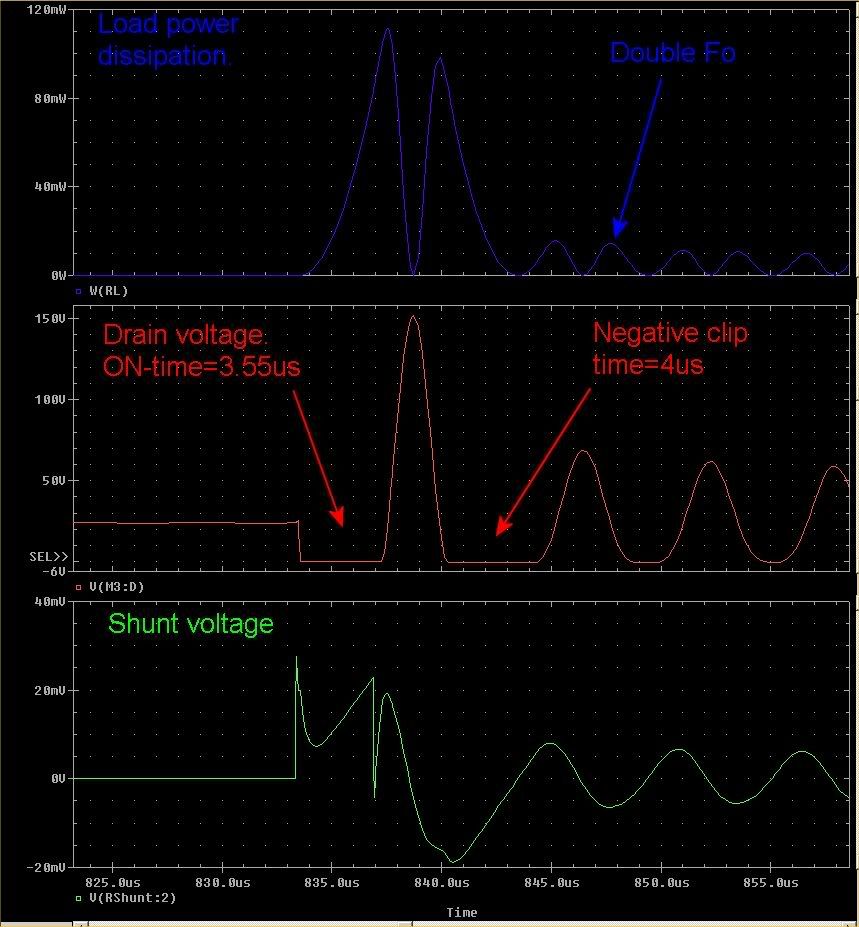
                          Saturation is not being reached even in my original shots with the 864uH. I have reduced the pulse width to 3.5us (from 15.4667us) and achieved a slightly longer clip time than ON time. This is well below inductor saturation.

                          Then I would like to see the net power for B(-) and B(+) using the drain as the reference. I think spice will let you float the battery and ground the drain for scope reference, it will make things easier for the analysis if we are looking at those power curves already referenced to that point. I think the reason will become clearer later. We need to run the simulation for a bit as I suspect there will be a harmonic accumulation that you will see after a minute or so of running, if it is in resonance. You may want to sweep it to find the optimum resonant frequency, and then experiment with different sweep rates while using that as the fundamental center frequency of your sweep. We have not discovered the frequency's rate of change yet.

                          The goal here is to show in the simulation how the battery will react to current flow into a circuit node that has a lower potential than both of its terminals and how that impacts the power readings for both terminals. This is why the more clipping we show with the body diode the better.

                          Thanx again for your efforts here, it is appreciated.

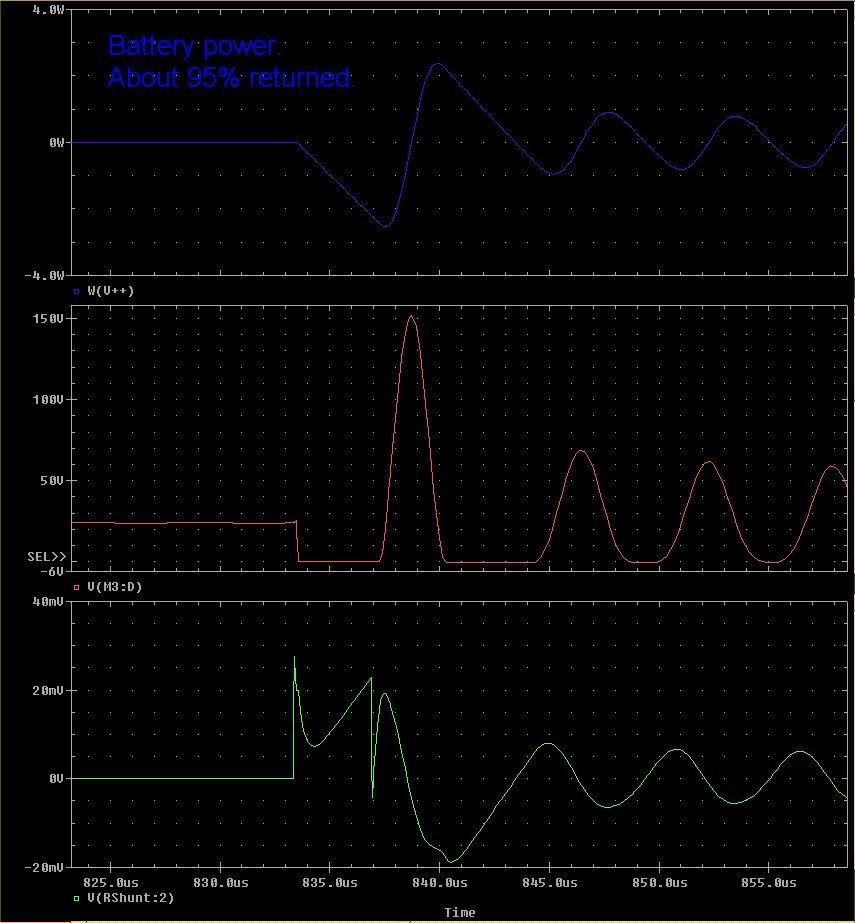
                          I have been able to show with this setup that most of the energy gets returned to the battery, say about 95%. It was interesting to see double the resonant frequency in the resistive part of the load. This is the result of the instantaneous power calculation and the fact that the V and I is changing polarity every half cycle (-'ve x -'ve = +'ve value).

                          So we see that very little net power is being used from the battery down at these settings with a very low pulse width driving the MOSFET/load. Average power dissipation in the load is in the low mW range.

                          By increasing the frequency (and decreasing the pulse width accordingly), a similar effect will take place with a much smaller inductance. I have already shown similar effects by driving the 8.64uH at 454kHz. A similar analysis could be done with the above in mind.

                          Harvey regarding your request for the Drain as a reference etc., I'm not sure what you are after here exactly. I can take differential voltage measurements across any two points in the circuit if that will help. Let me know.

                          Attached are two scope shots:
                          1. is of the Load power, Drain voltage, and shunt voltage together
                          2. is the same, but instead of Load power it shows battery power.


                          .99

                          ref files: harvey01.jpg and harvey02.jpg

                          Comment


                          • Originally posted by witsend View Post
                            Golly Fuzzy. Getting better and better.
                            Hi Rosemary,

                            The small corrections I've made to duplicate the replication of the "Ainslie-Murakami Negative Dominant Waveform Generator" appears to have worked, giving results now that should be able to be measured easily.

                            I'm still concerned on the apparent "LOSSES" that are happening through the osicilliscope probe "ground" connections and the gains that could be added to the battery that are going elsewhere.

                            I guess it's now down to my previous posting POST #2450 / 9-3-09

                            Quote :
                            The consensus for a approve method to measure the current on the RA circuits from members here at Energetic and at Over Unity will be needed to resolve the issue only if small amounts can be produced unless there are larger differences through replications using other "Load" 10 ohm resistors with mH impedance values or other substituted components. This battle is to the others, the replicators will all be waiting here soon for your answers, as for the replicators we should not to be bias one way or the other. Our ( replicators ) bottom line is, the obtained readings we may achieve for any verification, there just needs to be a agreed method of measurement .......

                            It's now here for the "Ainslie-Murakami Negative Dominant Waveform Generator" circuit .... so I can go on to your "Rosemary Anislie COP> 17 Heater Circuit" the Revised: August 12, 2009 first and the original Quantum circuit .... using the correct "liquid" lead acid batteries and 10 ohm wire wound "LOAD" resistor which as you know no one has done replicating these circuits other than possibly Aaron.

                            If by some chance there is no wide consensus on the measurement issue I will have no alternative but to go "Wild Cat" and use proven processes already applied, but may not be agreed upon by everyone, as I already discussed with you and some others.

                            Best Wishes
                            Glen
                            Last edited by FuzzyTomCat; 09-07-2009, 08:06 PM.
                            Open Source Experimentalist
                            Open Source Research and Development

                            Comment


                            • @Ash

                              Originally posted by ashtweth View Post
                              The resistor I used was a 10 ohm 200W wirewound (RS Australia part# 169-950). They didn't have a 100W resistor but they sell as high as 1KW. Higher resistance values are available - does anyone advise against using a higher resistance or a variable wirewound resistor or experimenting with voltages?
                              All the resistors I'm using are variable except one. But I have taken the sliding clamp off of the ones I'm using so no variability. The wire is simply exposed along one side of the resistors. I have used from 1 ohm up to 1500 ohms as a load but am mostly focusing on 10 ohms.

                              Wattage ratings are from 50 up to 250 watts or so.

                              24V is the most voltage I used.

                              What I really want is 20awg 15.83 feet long wound into a coil like the quantum article states. The quantum specs appear to show that the wire would be 12awg but at 15.83 feet long, it would only have about 1.5 ohms and if the quantum coil is really 10 ohms, then it would have to be 20awg to have 10 ohms at 15.83 feet long.

                              I'll post a video that might be helpful to experimenters... in the next few hours possibly.
                              Sincerely,
                              Aaron Murakami

                              Books & Videos https://emediapress.com
                              Conference http://energyscienceconference.com
                              RPX & MWO http://vril.io

                              Comment


                              • @Glen & Harvey & all

                                Thanks Glen and Harvey for answering questions and keeping the conversation going while I was gone.

                                @Harvey - the 3 resistor measurements that you're talking about - are you talking about placing them exactly one on each leg of the mosfet?

                                Anyway, I'll post a video that I hope will answer some questions - and no doubt will bring up more.

                                I would suggest everyone look at this for a moment:
                                Negative resistance - Wikipedia, the free encyclopedia


                                I don't know if in the mosfet there is the same type
                                of negative resistance effect that violates ohms law
                                but there are non-linear zones exactly like this on
                                the irfpg50 depending on the settings. I'll show what
                                I mean in a video.
                                Sincerely,
                                Aaron Murakami

                                Books & Videos https://emediapress.com
                                Conference http://energyscienceconference.com
                                RPX & MWO http://vril.io

                                Comment

                                Working...
                                X