Announcement

Collapse
No announcement yet.

COP 17 Heater | Rosemary Ainslie

Collapse
This topic is closed.
X
This is a sticky topic.
X
X
 
  • Filter
  • Time
  • Show
Clear All
new posts

  • 10ohm resistor

    What are people using for the 10 ohm resistor?

    I found this:
    D225K10R - OHMITE RESISTOR, 10 OHM, 225 WATT, ADJ. TUBULAR, WIREWOUND, +-10% TOLERANCE

    Item Number: D225K10R
    Manufacturer: OHMITE
    Item Category: Resistors
    Subcategory: Bracket Mount
    Series: WIREWOUND POWER
    Height: 1.13 Inches
    Width: 10.5 Inches
    Depth: 1.13 Inches
    Resistance: 10 Ohms
    Watts: 225
    Adjustable: Y
    Composition: Ceramic
    Package Type: Tubular
    Terminal Type: Radial Lugs
    Tolerance (%): -10~10 Percent
    Volts AC Max.: 4595 Volts AC
    Dielectric Voltage: 3000 Volts
    Temp Coefficient (ppm/C): 260
    H x W x D (in.): 1.13 x 10.5 x 1.13

    It's a little larger then the specifications and doesn't give the number of turns.


    The schematic on page 1, there is a diode above the 12V battery that doesn't have a value. What should I use for this Diode?

    The 1N4148 Diodes - does it matter what voltage, current or speed rating to use? DigiKey.com has many configurations available.

    Thanks,
    Last edited by dllabarre; 09-11-2009, 02:13 PM. Reason: add
    Don

    Comment


    • Originally posted by witsend View Post
      Lighty - I tried to read your link. Is there any chance of getting a translation here? I'm sure there are a number of us who'd be interested.

      What link?
      http://www.nequaquamvacuum.com/en/en...n/alt-sci.html
      http://www.neqvac.com

      Comment


      • Originally posted by lighty View Post
        What link?

        I think she's referring to the link under your name, your signature link.
        I viewed it and it's not English.
        Don

        Comment


        • I'm not even trying to do anything practical. ATM I'm over my head with some bureaucratic stuff that I postponed for some time. Bleh.

          You're quite right about different construction of IGBT and MOSFET. In fact in general terms IGBT can be treated as voltage controlled BJT.The thing is that when MOSFET is fully opened it will allow for current passing both ways while opened BJT will not allow for that. Their main difference is that BJT is basically represented as equivalent of two diodes with common cathode or anode. MOSFET however is of quite different nature and allows for bi-directional passing of current. The main problem with MOSFET is it's rather large intrinsic capacity in comparison with BJTs.

          As for the freewheeling diode (indeed better term in this particular case is flyback diode) I did suggest to use hyperfast type with as low forward voltage drop as possible. If one choose to use IGBT which already have built-in freewheeling diode one can also use hyperfast diode in parallel but recovery time will then be that of the freewheeling diode.

          Now, as for using IGBT for this particular purpose. The moment one introduces series blocking diode one did nothing else but compensated for MOSFETs bidirectionality and the result is that it's directionality characteristics will in that case match that of BJT. The problem with the series diode and MOSFET combination is that it introduces additional forward voltage drop and thus additional power dissipation, so in the end one ends up with forward voltage drop of diode + Rds. In case of using IGBT as I suggested it would be only C-E voltage drop and the directionality would be the same as with MOSFET + series blocking diode. On the other hand with the appropriate selection of MOSFET and series blocking diode one could cut power dissipation to about 12% of the power dissipation of the original circuit.

          Also, I don't quite understand why would anyone want to use IRFPG50. It's a high voltage MOSFET with terrible switching and electrical characteristics. It has very large input and output capacitance (slower rise/fall time) and just awful Rds (2 Ohm). That MOSFET itself is a terrible power dissipator because with slower rise/fall times you spend more time in the linear region which translates directly into power dissipation. Also Rds of 2 Ohm is extremely high by any standards. The only reason one would want to use that particular MOSFET is if one want to switch voltages over 800V. In this particular case voltage to be switched is under 30V. Add to that series blocking diode and that's horrible.

          Lets do a simple calculation and lets assume that rise/fall time of IRFPG50 is reasonable. If we have continuous current of 1A going through the MOSFET when it's turned one that means that we will have power dissipation of P= R * I^2 = 2 Ohm * 1 A = 2W. So, we already lost 2W of energy into heat. Now, if average diode has forward voltage drop of around 0.6V that means that on the diode itself we will have power dissipation of P = 0.6 V * 1 A = 0.6W. So, with IRFPG50 with series blocking diode we have about 2.6W of losses. Of course with pulsing DC the losses will be lower but in that case we should calculate energy losses in Joules rather than in Watts. In any case we are doing the comparison of the different setup and their relationships will remain same in any case.

          By using common IRFP450 (there are much better MOSFETs out there but this one is rather common) we could cut losses by about 2.5 times. The calculation is simple - Rds is max 0.38 Ohm so let's use that value. P = 0.38 * 1 = 0.38W.
          So with IRFP450 total power dissipation with blocking series diode gets to be about 0.98W which is about 2.5 times less then in case of IRFPG50.

          Now, if we use some MOSFET with even less Rds and with smaller maximum current (we are not trying to push 14A which is maximum continuous rating of IRFP450 or 6A which is maximum continuous rating of IRFPG50. Let's say we want to use about 3A. Then even a commonly used BUZ11 gets much better performance. For example BUZ11 Rds is 0.04 Ohm so the power dissipation will be P = 0.04 * 1 = 0.04W. Compare that to IRFPG50's 2W of power dissipation. So in this case total power dissipation with series blocking diode would be around 0.64W which is about 4 times less then with IRFPG50. Of course maximum D-S voltage of BUZ11 is 50 V and maximum current rating is 30 A but if voltages under 50V are used then this approach is much simpler. Ah, and since intrinsic capacitances of BUZ11 are smaller it's rise/fall time should also be better. In other words over-engineering is not always better.

          Now, if Schottky diode is used for series blocking diode and it usually have forward voltage drop around 0.2-0.4V that means that power dissipation of diode can also be cut in half.

          So, let's see the case with BUZ11 and some Schottky diode. It's total dissipation would be about 0.04W + 0.3W = 0.34W. Now compare that to IRFPG50 with standard rectifier diodes which has power dissipation of about 2.6W. We managed to cut power dissipation to 1/8 of the power dissipation of the original circuit.
          Last edited by lighty; 09-11-2009, 03:15 PM.
          http://www.nequaquamvacuum.com/en/en...n/alt-sci.html
          http://www.neqvac.com

          Comment


          • Originally posted by dllabarre View Post
            I think she's referring to the link under your name, your signature link.
            I viewed it and it's not English.
            In fact there is an English language section and Alternative science section. Sometimes I write for various magazines in Croatia and later I put articles on webpage. It would take great amount of my time to translate everything to English. However you can access English section/Alternative Science here Alternative Science

            There is also alternative science section in Croatian language with one article about ground radio from historical and practical point of view.


            P.S.
            It also seems links in my signatures were not correct so I corrected them.
            Last edited by lighty; 09-11-2009, 03:20 PM.
            http://www.nequaquamvacuum.com/en/en...n/alt-sci.html
            http://www.neqvac.com

            Comment


            • Originally posted by dllabarre View Post
              What are people using for the 10 ohm resistor?

              I found this:
              D225K10R - OHMITE RESISTOR, 10 OHM, 225 WATT, ADJ. TUBULAR, WIREWOUND, +-10% TOLERANCE

              Item Number: D225K10R
              Manufacturer: OHMITE
              Item Category: Resistors
              Subcategory: Bracket Mount
              Series: WIREWOUND POWER
              Height: 1.13 Inches
              Width: 10.5 Inches
              Depth: 1.13 Inches
              Resistance: 10 Ohms
              Watts: 225
              Adjustable: Y
              Composition: Ceramic
              Package Type: Tubular
              Terminal Type: Radial Lugs
              Tolerance (%): -10~10 Percent
              Volts AC Max.: 4595 Volts AC
              Dielectric Voltage: 3000 Volts
              Temp Coefficient (ppm/C): 260
              H x W x D (in.): 1.13 x 10.5 x 1.13

              It's a little larger then the specifications and doesn't give the number of turns.


              The schematic on page 1, there is a diode above the 12V battery that doesn't have a value. What should I use for this Diode?

              The 1N4148 Diodes - does it matter what voltage, current or speed rating to use? DigiKey.com has many configurations available.

              Thanks,
              Hi dllabarre,

              The 10 ohm resistor for the "Rosemary Ainslie COP>17 Heater Circuit" is a custom made resistor -
              The load resistor was made by Specific Heat CC (SA). It comprises a 10 ohm hollow core wire wound ceramic structure with a length of 150 mm (5.9055 in long). and a diameter of 32 mm ( 100.5308 mm / 3.9579 in circumference ). 48 turns of resistance wire (4825.4784 mm / 189.9795 in / 15.8316 ft long) are spaced at 1 mm. It was chosen for its inductance (8.64 micro Henries).

              48 turns - 10 ohms @ 15.8316 feet = .63165 ohms ft
              AWG 20 [.032 dia] ( .6348 ohms ft ) = ( 10.0499 ohms ) "Ni Cr A" 80% nickel, 20% chromium

              I'm using a MEMCOR # FR100 10 ohm which are in my posted build photographs and will be winding my own resistor using some 32 mm OD. "Borosilicate Glass Tube" ( Pyrex ) to copy the replication.

              The diode that is missing the information is a 1N4007

              The 1N4148 diodes can be substituted with a 1N914 are being used

              I hope this helps in your build

              Glen
              Last edited by FuzzyTomCat; 09-11-2009, 05:41 PM. Reason: circumference not diameter on 32 mm measurements
              Open Source Experimentalist
              Open Source Research and Development

              Comment


              • body diode bypass

                Originally posted by lighty View Post
                You only want to let current pass in one direction like from drain through source, right? And that's why you using blocking diode, correct?
                Hi Lighty,

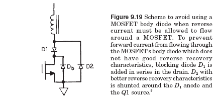
                The concept is to switch the mosfet on which lets the battery charge the inductive reisistor. When the mosfet switches off, the body diode allows the collpasing magnetic field to conduct back to the battery sending back recovery.

                However, from what I've read, the body diodes of all mosfets are basically junk.

                So the blocking diode is supposed to prevent the body diode from conducting reverse current back to the battery on the collapse while the parallel diode does allow the revese current to be conducted around bypassig the body diode with a better quality diode.

                When I used a 6A100 blocking diode (very slow) and a 1n914 parallel diode, I was able to get a few degrees hotter at the inductive resistor while the current leaving the battery dropped 1.3 watts.

                That showed me that bypassing the body diode with a better quality diode significantly increases efficiency.
                Sincerely,
                Aaron Murakami

                Books & Videos https://emediapress.com
                Conference http://energyscienceconference.com
                RPX & MWO http://vril.io

                Comment


                • lighty,

                  The flyback diode I am referencing is across the inductor, not the switch. I think you stated not to use one and that a 30V or 20V device will be adequate. What I was trying to convey was that this particular circuit not using an inductor flyback diode will exhibit quite high flyback voltages which stress the switch, and depending on switch speed and inductance, can be as high as 2kV. Certainly 300V is not uncommon here.

                  So, although I agree with you that the IRFPG50 is crap as a switch, one of the main reasons it is used here is to tolerate any high flyback voltages and not fail.

                  Incidentally, when the MOSFET is OFF, it is at a high enough resistance that very little current conducts through it. Also, the reverse biased diode present in the MOSFET model, is desirable in that under certain conditions the flyback voltage will go negative for one-half cycle of resonance, and during this period battery recharge is allowed.

                  .99

                  Comment


                  • Originally posted by Aaron View Post
                    However, from what I've read, the body diodes of all mosfets are basically junk.
                    They are not junk for most purposes and when not dealing with very fast rise times and high repetition rates. For this purpose however they are a bit junky that's true.


                    So the blocking diode is supposed to prevent the body diode from conducting reverse current back to the battery on the collapse while the parallel diode does allow the revese current to be conducted around bypassig the body diode with a better quality diode.
                    I understand what you're trying to do with parallel diode used for bypasing intrinsic diode but I don't really understand why would you need blocking diode? If you turn off MOSFET fully then it will block inductive collapse by it's very nature and parallel diode would act as bypass back to battery and to protect MOSFET at the same time. Am I missing something here?


                    That showed me that bypassing the body diode with a better quality diode significantly increases efficiency.
                    Read my above post about using better quality components and check the simple math I used to explain to explain rudimentary basics of choosing proper components. As it is at the moment you are dissipating about 8 times more energy then necessary on inadequately chosen components.
                    http://www.nequaquamvacuum.com/en/en...n/alt-sci.html
                    http://www.neqvac.com

                    Comment


                    • Hi Aaron,

                      I was looking at your possible modification to the IRFPG50 Mosfet, and found some components that should match the Mosfet specifications fairly close and with higher performance.

                      1) low on state blocking diode NTE Electronics - NTE586
                      http://www.nteinc.com/specs/500to599/pdf/nte586.pdf

                      2) fast switching parallel diode NTE Electronics - NTE597 ( w/ heat sink and mica insulator )
                      http://www.datasheetcatalog.org/data...nte/NTE597.pdf
                      "or" (2) 1n914 fast switching diodes in parallel

                      Any thoughts ?

                      Glen
                      Last edited by FuzzyTomCat; 09-14-2009, 01:01 AM. Reason: diode descriptions reversed - sorry !!
                      Open Source Experimentalist
                      Open Source Research and Development

                      Comment


                      • Originally posted by poynt99 View Post
                        The flyback diode I am referencing is across the inductor, not the switch.
                        I think we have a major misunderstanding here. What inductor diode? Are we looking at the same circuit? I can see on first page of this thread circuit with IRFPG50? Is that the proper one or are we talking about the second schematic by Peter?
                        http://www.nequaquamvacuum.com/en/en...n/alt-sci.html
                        http://www.neqvac.com

                        Comment


                        • Ah, I suppose we're discussing Peter's schematic.

                          It's even simpler this way. Diodes D1 and D2 should be ones with as low voltage drop as possible with as short recovery time as possible. Again Schottky diodes are the only viable solution in this case.

                          Diodes D3 and D4 should of course be as fast as possible. Possibly one of the hyperfast types of diodes.

                          As for the MOSFET it doesn't seem that D-S voltage will go so high because most of it would be snubbed by recuperating capacitor C through diodes D3 and D4.

                          However if one wants to be completely certain I have a few suggestions.

                          1. Use IRFGP50 but parallel a few of them in order to keep total Rds on some reasonable levels. I don't think that is necessary because of the snubbing properties of the D3, D4, C portion of the circuit.

                          2. Use some higher voltage MOSFETS but with much lower Rds than IRFPG50. I doubt D-S voltage will ever get so high anyway.

                          3. Use lower voltage MOSFETs like BUZ11 but put in parallel suppression diodes of let's say 47V. Those protection diodes open in matter of pico-seconds and are more than adequate to protect MOSFETs. They also can dissipate up to 1500W peak power if necessary and come in unidirectional or bidirectional flavour. They are also rather cheap.


                          I would definitely opt for third option. Recovery/snubber circuit D3, D4, C will cut voltage spikes to reasonable levels and if some voltage remains transient suppression diode will bypass MOSFET and protect it. At least if protection diode get warm one can see that there are voltage spikes are present which are higher than it's threshold voltage (it's better to use oscilloscope to measure it, of course).

                          Of course MOSFET have to be properly driven in order to raise efficiency of circuit (short rise/fall times) so using high current MOSFET drivers or at least a BJT driver stage is very advisable. 555 output is simply not good enough for that job. I mean it will all work but if one is fighting for every Joule of energy saved then appropriate MOSFET, diodes and driving circuitry has to be employed.
                          http://www.nequaquamvacuum.com/en/en...n/alt-sci.html
                          http://www.neqvac.com

                          Comment


                          • 10 ohm resistor

                            @FuzzyTomCat and ALL

                            The 10 ohm resistor comprises a 10 ohm hollow core wire wound ceramic structure with a length of 150 mm (5.9055 in long). and a diameter of 32 mm ( 100.5308 mm / 3.9579 in circumference ). 48 turns of resistance wire (4825.4784 mm / 189.9795 in / 15.8316 ft long) are spaced at 1 mm. It was chosen for its inductance (8.64 micro Henries).

                            48 turns - 10 ohms @ 15.8316 feet = .63165 ohms ft
                            AWG 20 [.032 dia] ( .6348 ohms ft ) = ( 10.0499 ohms ) "Ni Cr A" 80% nickel, 20% chromium


                            So I gather from this that getting 10 ohms AND 8.64 micro Henries is what's important in reproducing this resistor to maintain the circuits performance?

                            Thank you,
                            Don

                            Comment


                            • diodes

                              Originally posted by lighty View Post
                              I understand what you're trying to do with parallel diode used for bypasing intrinsic diode but I don't really understand why would you need blocking diode? If you turn off MOSFET fully then it will block inductive collapse by it's very nature and parallel diode would act as bypass back to battery and to protect MOSFET at the same time. Am I missing something here?

                              Read my above post about using better quality components and check the simple math I used to explain to explain rudimentary basics of choosing proper components. As it is at the moment you are dissipating about 8 times more energy then necessary on inadequately chosen components.
                              I tried out the blocking and bypass diode and found that this scheme is used in quite a few setups:


                              Are you saying if mosfet is off that the body diode isn't supposed to
                              conduct? I thought that when the mosfet is off, it is the body diode
                              that able to conduct in the reverse direction so the collapse magnetic
                              field can send the spike back to the front battery.

                              Anyway, I can remove blocking diode and see what happens. but I
                              did notice that with a blocking diode there but no parallel diode,
                              the spikes are still getting to the battery. Diode probably not fast enough
                              to shut off the spike.

                              I get it about using the right components - for the diodes, I'm just
                              using what I have on hand. Will have to order some better ones.
                              Sincerely,
                              Aaron Murakami

                              Books & Videos https://emediapress.com
                              Conference http://energyscienceconference.com
                              RPX & MWO http://vril.io

                              Comment


                              • schematic

                                Lighty, this is the schematic I'm using:

                                The values on the timer circuit may be different and I have a pot
                                between the battery and the timer circuit positive to vary how much
                                power I want it to have. And I have the timer powered by the same
                                battery as the load.

                                The 10 ohm resistor on the left side of the circuit is an inductive
                                resistor.

                                Sincerely,
                                Aaron Murakami

                                Books & Videos https://emediapress.com
                                Conference http://energyscienceconference.com
                                RPX & MWO http://vril.io

                                Comment

                                Working...
                                X