Originally posted by poynt99
View Post
Announcement
Collapse
No announcement yet.
COP 17 Heater | Rosemary Ainslie
Collapse
This topic is closed.
X
This is a sticky topic.
X
X
-
Harvey - I missed this. The Fluke scope is battery operated. Did we misrepresent this in the paper? I hope not. On the rare occassions that we ran it 'plugged in' it made no real difference to the measurements. I hope this answers the question.Originally posted by Harvey View PostYou'll notice that there are really 3 batteries. Two in series for the 24V and a single separate battery for the timer. I have to admit, for my tests I did not provide a separate battery for the timer circuit - instead, I tapped the timer off the intermediate junction between the two series batteries. All of the 'grounds' were shared and bonded to an 8' copper rod in the ground via the scope probe references and scope chassis ground. A separate path to earth was strictly avoided to prevent ground loop currents. Therefore, in my case the circuit itself was 'free floating', only being tied to Earth via the scope chassis. There was no noticeable difference between having two references connect or just one, even though if a potential did exist it could have looped through those parallel circuits. The Ainslie circuit in the white paper clearly shows a zero reference being tied to the circuit, and that same reference is schematically shown as the scope chassis. How this was accomplished physically, I do not know specifically. Since the unit was operated at more than one location, it is reasonable to conclude that the zero reference was probably tied to the scope chassis or electrical earth ground by some wire. How much and by what wire gauge, we would need to ask Rosemary.
Cheers,

Comment
-
Hi ALL
Here is the report , we will also be moving onto Aaron latest, lets see How far we can push that 555 timer in the real world, doesn't mater if it fails, Rose still shows an IO/O even if it wont last on the farm.. more to come guys.
Schemo used
Imageshack - quantumschematic6
Set up
Imageshack - setuppg
2_4KHz 3_7%
Imageshack - 24khz37
first negative dominant generator
Imageshack - firstnegativedominantge
http://www.turboimagehost.com/p/2122...lunt_spike.jpg
capacitor loaded resistor blunt spike
report
----------
Hey all,
I have built a new 555 timer board calibrated to exactly 2.4KHz 3.7% duty cycle and tested it. The same 10 Ohm 200W resistor has been used. The frequency / duty cycle meter was checked for accuracy using a signal generator computer program / sound card.
The circuit consumed 100mA at 24V.
The ambient temperature was 21C / 70F
The resistor temperature was 32C / 90F.
The same 4700uF / 50V capacitor and 470 Ohm resistor load were used.
Leaving the capacitor on charge for longer than half an hour it charged up to 25.2V and when I connected the 470 Ohm resistor, the voltage rapidly fell to 180mV under load.
I notice the oscilloscope spike waveforms are sharper when the capacitor is charged, but when the capacitor is loaded, the spike is blunt.
I've built the August 12 2009 negative dominant generator and had slightly better luck with it.
The 4700uF 50V cap powers a 470 Ohm load at 1.1V
The circuit consumed 23.6V 1.1A
Ambient temperature: 24C / 75F
Resistor temperature: 83C / 181F
The maximum output frequency with the August 12 revision was 24KHz 42.5%
The Mosfet was slightly warm while operating.
I found the gate resistance had to be adjusted to see a normal waveform with negative spikes or else the waveform / mosfet oscillates wildly and heats up further.
I will be progressing onto the August 26 2009 revision (915KHz 55%) - it looks like it will deliver better results.
I read that the 555 timer is 5 deg C above ambient temperature operating at 915KHz! I wonder if we should be using an RLC / tank circuit somewhere around 1MHz to operate the mosfet - like how Dr Stiffler does his transistor driver in his SEC boards?
Does anyone have any suggestions, questions or comments?
AndrewLast edited by ashtweth; 09-14-2009, 06:31 AM.
Comment
-
Hi Ash,
There is a minor problem that you may have with RF or other types of frequency's that the Mosfet puts off during oscillations and its pointing towards the 555 timer and the Potentiometers and will effect them in adjustments and you will have a lot of adjustments so keep plenty of screw drivers handy. The Mosfet may also work better for you with isolating the "Drain" which is physically connected to the Mosfet back plane with some Mica or Sil -Pad from your "Heat Sink" it acts like a mini antenna.
PC Board Example ( Mosfet pointing away )
gotoluc post on groundloop's PC bare board
groundloop's finished PC board
Also there is two circuits ....
Rosemary Ainslie COP>17 Heater Circuit
Ainslie - Murakami Negitive Dominant Waveform Generator
This is my replication of the Ainslie - Murakami Negitive Dominant Waveform Generator circuit POST 2606
Glen Open Source Experimentalist
Open Source Research and Development
Comment
-
Hi .99Originally posted by poynt99 View PostWould anyone here care to sell an IRFPG50 or two if they have extras?
Thanks,
.99
A earlier Post of mine I offered you one for free for a "replication" if you could not afford one, I wasn't aware you were only doing "SPICE" modeling .....
POST 2152
PM me we "might" be able to come to a agreement @ $1.95 each Mosfet plus $5.00 for USPS Priority Mail ( I have only three now extra )@.99
What are you saying here? That anyone else's opinion including my replication I just started working and haven't received all my parts yet doesn't matter and what about the other Energetic members, doesn't there actual replication matter or have any influence here in this thread?
I don't understand what your insinuating with this broad statement?
How is your replication going?
Do you have any stats, data or photos of a replication to share with the group, or have I just missed them?
What's the hurry? I didn't realize there was a time table on this, whats the due date now????
Glen
------------------------------------------------------------------------
edit- If you need a Mosfet for your replication and cannot afford one, I will send you one "FREE" of charge just PM me !!!!
GlenOpen Source Experimentalist
Open Source Research and Development
Comment
-
Hi .99Originally posted by poynt99 View Post@ Glen
Check your inbox, you've got money!
Thanks
.99
The two Mosfets are packed up and will be shipped out tomorrow 09-15-09 USPS priority mail ..... have fun
Glen Open Source Experimentalist
Open Source Research and Development
Comment
-
I wish I had the time to work up a video of the simulations I have been working with to show how sensitive this circuit is. Seems like any time the things try's to truly go aperiodic Spice complains about not being able to converge properly - but I have at least obtained enough to move forward with my research. It looks like it will be at least a week before I can get a vid together as I have to leave town tomorrow and do a lot of catchup on return.
There are two areas specifically that have stood out.
1. Internal Capacitance of the Inductive Resistor:
This capacitance is usually considered to be across the resistive structure, however, in reality the bulk of it is parallel with the inductance. To accurately model this we would need a separate inductor-capacitor for each winding in series with a resistor-capacitor for each winding. This capacitance has a dramatic effect on how the energy is stored or dissipated in the resistor. I have modeled a single resistor from two 4.32uH inductors with a 10Ohm resistor in between. I specifically chose a resonate capacitance for each inductor of 0.0432uF to match the impedance of the resistor which results in a resonant frequency of 184.207KHz during the ring cycle. It is noteworthy that Spice recognizes no power as being dissipated in the resistor during this period. A 0.001nF was selected across the resistor and seems to be more important to the Spice convergence than to the resultant signal values.
2. Gate signal trailing edge slope:
This is not consistent in the physical model or the simulation. While the majority fall into a relative mean, sometimes the slope is very good and vertical. When this occurs, a healthy spike of voltage becomes present on the inductor and can sometimes exceed the avalanche voltage of the IRFPG50. These spikes can be so fast that they are hardly discernible. Other times the slope can be so poor that it nearly consumes all of the ring energy entirely right off the bat. When the slope is sharp and avalanche occurs, aperiodic action can initiate that cascades into further avalanche. This seems to be why the gate resistor plays such an important role - as all of the gate charge needs to be fully scavenged as quickly as possible to ensure an affirmative and complete switching in the shortest possible time.
Of what value are the ringing if they don't even register as power dissipation? I originally discounted dielectric heating because of the low frequencies this is operating at. But when I started seeing how those very narrow spikes can occur during the aperiodic operation I am convinced that this is a big part of what is happening. The frequency is not there in repetition, but the force that produces the dielectric heating is. The 'power' subtended in the ring energy is considered apparent power and if it is not dissipated in the resistance or dumped into the FET on the next gate pulse, it can be used to cause dielectric heating...if the delta magnetic peak over delta time is steep enough. When the 8.64uH Inductance is resonant, all of the ringing cycle is above ground far enough to prevent body diode conduction. The peak envelope is around 46V.
A good portion of the heat in the Ainslie test simply came from increased on time during aperiodic operation. Some of the power charted as heat was discounted during the subtraction of negative excursions. We don't have negative watts unless only one of our values is negative. IOW, negative voltage times negative current is positive watts. However, this some is a very small percentage of the whole. In fact, tests show it really only pertains to the negative going spike that occurs during the field collapse which can be less than 1us for an overall 400us period. And when compared to the 15us on time, we can see that this cannot account for all the extra power that seems to be consumed in the circuit.
So apart from normal heating, a minor miscalculation and dielectric heating, the only other classical contributor could be a form of Radio-kinetic action. Similar to Sonoluminance but in reverse and not in the visible spectrum. If the specific resistor was sensitive to the RF frequency and at a molecular level was able to convert that energy to molecular movement, then heating could occur from the RF aperiodic action. In this case, the RF may not have even been able to leave the enamel. I have had noteworthy RF action and so has Aaron. In my case, the resistor was close to my keyboard and provided enough interference so as to type all types of things. I had to position the cursor in notepad during my tests and hope that the ALT key didn't get transmitted. At any rate, that energy may have been wholly conserved in the Ainslie resistor and converted to heat.
Well, I'm out of time for now - will check back when I get back in town.
Cheers,
 "Amy Pond, there is something you need to understand, and someday your life may depend on it: I am definitely a madman with a box." ~The Doctor
Comment
-
pm
Hi Glen, send you a pm.Sincerely,
Aaron Murakami
Books & Videos https://emediapress.com
Conference http://energyscienceconference.com
RPX & MWO http://vril.io
Comment
-
10 Ohm Resistor
Hi everyone,
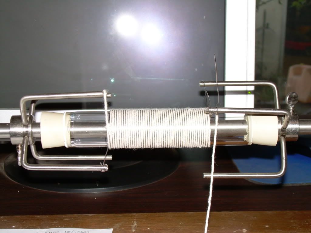
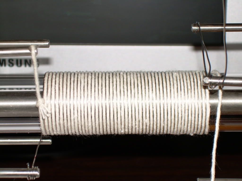
I just finished my "Borosilicate Glass Tube" ( Pyrex ) 10 Ohm Wire Wound Prototype Resistor, it's specifications are - 32 mm OD. x 6 inches long, 48 turns of AWG 20 [.032 dia] ( .6348 ohms ft ) "Ni Cr A" 80% nickel, 20% chromium resistance wire @ 1mm (+ -) Spacing.
Rosemary Ainslie COP>17 Heater Circuit Quantum - October 2002
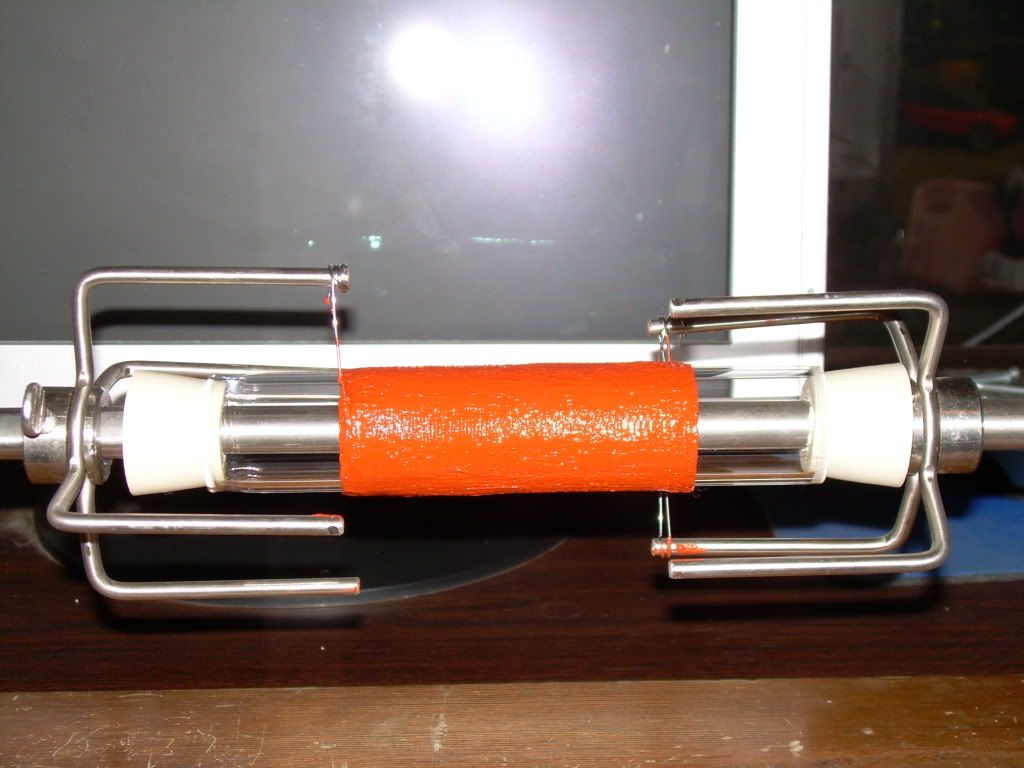
The outer covering is "Permatex" Red High Temp RTV Silicone - Continuous Operating Temperatures °C (°F) -54 to 316 (-65 to 600)
Red High Temp RTV Silicone #81409
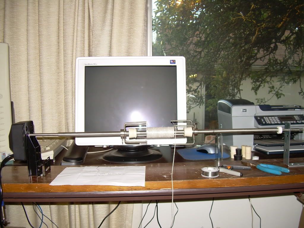
Here are some photos of my "Barbecue" coil winder, the last photo is with string removed and RTV silicone covering ....... drying now ...... testing is tomorrow


Glen Open Source Experimentalist
Open Source Research and Development
Comment
-
Looks nice.Originally posted by FuzzyTomCat View PostHi everyone,
I just finished my "Borosilicate Glass Tube" ( Pyrex ) 10 Ohm Wire Wound Resistor, it's specifications are - 32 mm OD. x 6 inches long, 48 turns of AWG 20 [.032 dia] ( .6348 ohms ft ) "Ni Cr A" 80% nickel, 20% chromium resistance wire.
The outer covering is "Permatex" Red High Temp RTV Silicone - Continuous Operating Temperatures °C (°F) -54 to 316 (-65 to 600)
Red High Temp RTV Silicone #81409
Glen
What inductance is your resistor?Don
Comment
 The PDF is all up to date now too for others
Comment