Announcement

Collapse
No announcement yet.

COP 17 Heater | Rosemary Ainslie

Collapse
This topic is closed.
X
This is a sticky topic.
X
X
 
  • Filter
  • Time
  • Show
Clear All
new posts

  • Latest circuit.

    Hello Peter , Aaron, I tried to read as many of the posts that I can out of the 2,700 posts

    I am going to build the circuit and do some research with Btu's gained using water, I have post #1924 as being the latest and greatest circuit for replication ease, is that correct Aaron?

    Ken

    Comment


    • @Ken

      Hi Ken,

      I would say that general circuit is good but you will have to swap out the resistors and caps on the 555 timer circuit to get the ranges you want.

      I have done many tests using separate shunts to independently measure the 555 power draw and the load draw and have used one single shunt to measure both at same time (this is with powering 555 and load from the exact same battery).

      Most variations of the schematics I posted are almost identical and the main difference are the resistor/cap values on the 555 circuit.

      Harvey has his own 555 timer mod he suggested.

      I posted Lighty's suggested schematic to use an opto isolator between 555 and load size of circuit - which if the effect is dependent on the material of the inductive resistor wire, then it could possibly work better.

      I built Lighty's Schmidt trigger and totem pole driver but it didn't work. I think the used transistors I used are fried. Have to replace those and it should work fine.

      Once you build the basic 555 circuit, it is easy to set all the rest up. Post some pics and any mods to the schematic if you make any and we can walk you through what we have done.

      Also, with super high frequencies on the 555, that is super low power not to make heat but just to show the point that we can get a net negative wattage from the battery, meaning there is more going to the battery than leaving.

      With slower frequencies and more power, that is for actually making heat, which I am moving back to.

      Glad to see someone else interested in building!
      Sincerely,
      Aaron Murakami

      Books & Videos https://emediapress.com
      Conference http://energyscienceconference.com
      RPX & MWO http://vril.io

      Comment


      • Originally posted by Aaron View Post
        Hi Ken,

        I would say that general circuit is good but you will have to swap out the resistors and caps on the 555 timer circuit to get the ranges you want.

        I have done many tests using separate shunts to independently measure the 555 power draw and the load draw and have used one single shunt to measure both at same time (this is with powering 555 and load from the exact same battery).

        Most variations of the schematics I posted are almost identical and the main difference are the resistor/cap values on the 555 circuit.

        Harvey has his own 555 timer mod he suggested.

        I posted Lighty's suggested schematic to use an opto isolator between 555 and load size of circuit - which if the effect is dependent on the material of the inductive resistor wire, then it could possibly work better.

        I built Lighty's Schmidt trigger and totem pole driver but it didn't work. I think the used transistors I used are fried. Have to replace those and it should work fine.

        Once you build the basic 555 circuit, it is easy to set all the rest up. Post some pics and any mods to the schematic if you make any and we can walk you through what we have done.

        Also, with super high frequencies on the 555, that is super low power not to make heat but just to show the point that we can get a net negative wattage from the battery, meaning there is more going to the battery than leaving.

        With slower frequencies and more power, that is for actually making heat, which I am moving back to.

        Glad to see someone else interested in building!

        Excellent info, thanks for the quick reply Aaron !

        I will let you know of the progress, I think I have most of the parts for it. I will keep to the published schematic as accurately as I can, have some spools of Nichrome wire in the basement I could test with only AFTER I can get the published circuit to 'ring'.

        Ken

        Comment


        • Tektronix TDS 3054C Testing - Part #1

          Hi everyone,

          This past week has been a busy one gathering all the information and compiling it from the testing that was done. As some of you may be aware that I have a working replication of the Ainslie - Murakami Negitive Dominant Waveform Generator circuit and have already shown my earlier results in POST #2606 and indicated that my Tektronix 2445A 150Mhz Oscilloscope was just not able to make the fine adjustments and record any data that could further this replication.

          I contacted Aaron and was allowed to travel to his home some 550 miles away to use the Tektronix TDS 3054C that was on loan to Energetic Forum and presently in Aaron's possession. This was kinda funny because I live not more than 15 miles from Tektronix's Complex and Corporate offices in Wilsonville & Beaverton, Oregon.

          I can not thank Aaron enough for his help and hospitality also Lisa from Tektronix for the opportunity to use one of the finest pieces of equipment I have had to view it's operation and use ..... basically my Tektronix 2445A I was 50% blind on what was happining in the replicated circuit and without any quality recording capability.

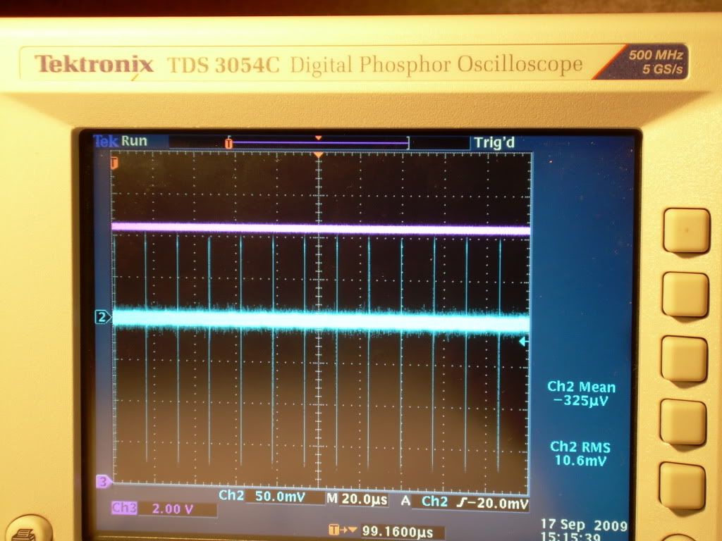
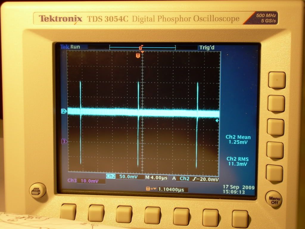
          TEST #1

          Replication Components - ( Items #1 through #4 used in both TESTS #1 and #2 )

          1) International Rectifier - IRFPG50 HEXFET® Power MOSFET
          w/ Sil-Pad insulator between Mosfet and Heat Sink

          2) Fairchild Semiconductor - NE555N Timer

          3) Vishay Spectrol - SP534 Percision Potentiometer/ 10-turn 2-Watt

          4) Exide Technologies Battery "Liquid" Model # GT-H - TRACTOR 12V 12Ah CCA 235

          5) Original Test Load Resister "Clarostat" 10 ohm + - 5%, 225 watt, 64.7 uH ( never before used on my replicated circuit )

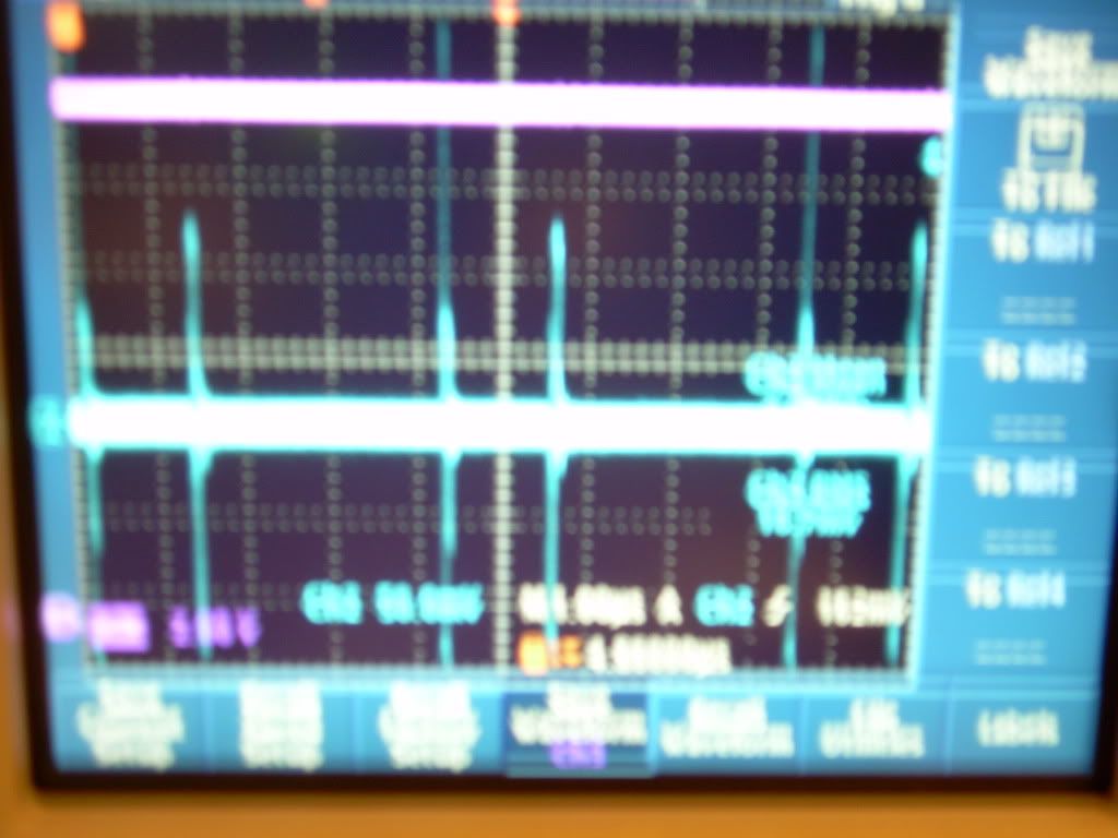
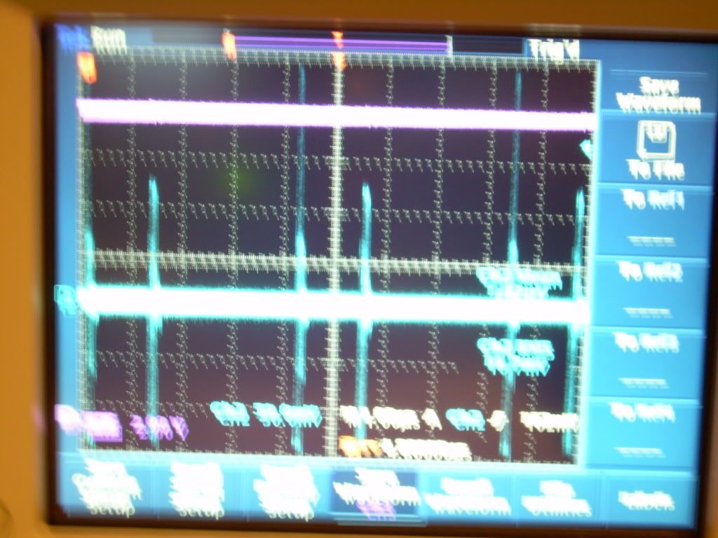
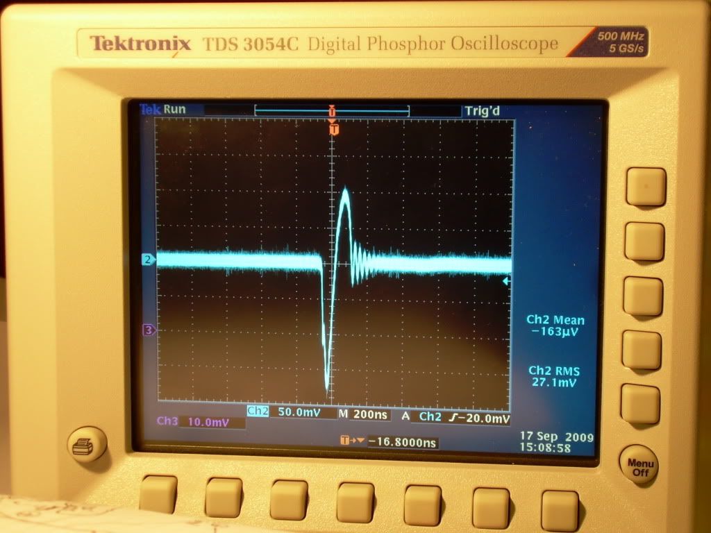
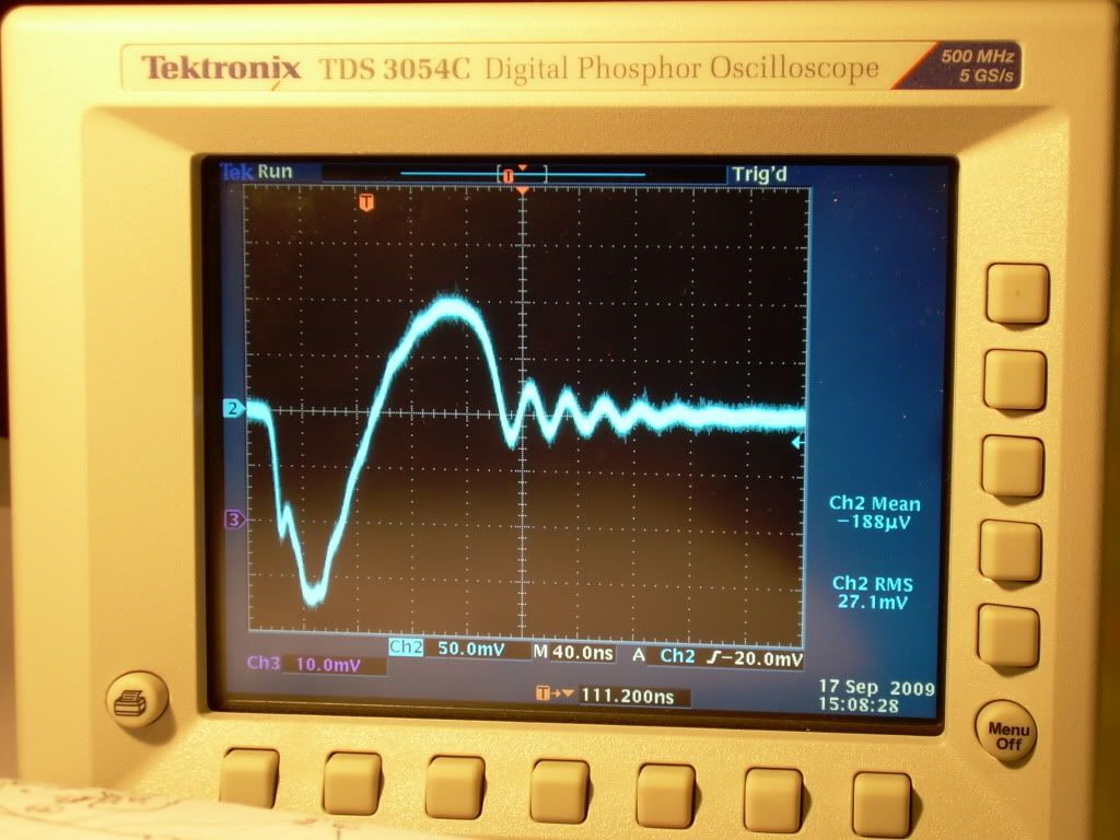
          Photos - 50 mV Div, 2us ( SORRY ... for the poor HD photos it was 12:00 am after traveling hours and hours it didn't happen a second time )


          Original 2us Data Dump (CSV file)
          Crunched 2us Data Dump (CSV file)

          I will be posting PART #2 shortly that one was the main reason of my travels

          Glen
          Open Source Experimentalist
          Open Source Research and Development

          Comment


          • I too have received Groundloop's PCB. Excellent Excellent Excellent! This little beau is premium professional quality PCB. WOW!

            Thanks again GL, Luc, and FuzzyTomKat.

            David

            P.S. Soldering up this baby now.

            Originally posted by poynt99 View Post
            On the Ainslie circuit note:

            I received Groundloop's PCB today in the mail.

            Thanks Luc, much appreciated!

            .99
            Last edited by eternalightwithin; 09-22-2009, 02:41 AM.

            Comment


            • Tektronix TDS 3054C Testing - Part #2

              Hi everyone,

              Here is the second test, as noted in the previous Test #1 components items #1 through #4 are the same ......

              TEST #2

              Components -

              1) International Rectifier - IRFPG50 HEXFET® Power MOSFET
              2) Fairchild Semiconductor - NE555N Timer
              3) Vishay Spectrol - SP534 Percision Potentiometer/ 10-turn 2-Watt
              4) Exide Technologies Battery "Liquid" Model # GT-H - TRACTOR 12V 12Ah CCA 235

              5) Quantum 10 Ohm + - 1% "Replication"
              6) "ADDED" 4,000 ohm resister in series between 555 power adjustment potentiometer and 1N914 diode positive rail

              Potentiometer Adjustments -
              1) Gate- .5 ohms
              2) On- 201.6 ohms
              3) Off- 317.3 ohms
              4) 555 Timer- 688.0 ohms ( "plus" 4,000 ohm resister "Total" = 4,688.0 ohms )

              Temperatures - ( constant + - .5 F )
              1) Mosfet- 76 degrees F
              2) 555- 76 degrees F
              3) 10 ohm Load resister- 76 degrees F
              4) Desk Top- 76.5 degrees F

              Battery Voltage - 12.45 VDC ( Fluke 87 )

              Additional Oscilloscope -
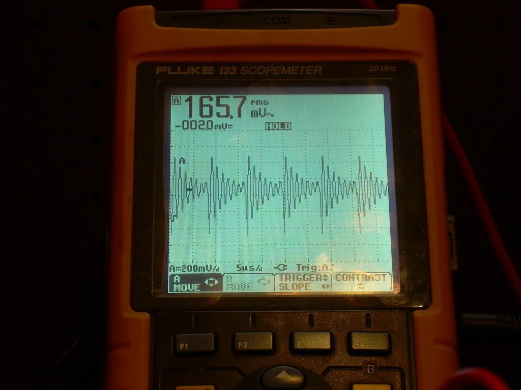
              Monitoring the 10 ohm "Load Resistor " Fluke 123 ScopeMeter


              Original 20us Data Dump (CSV file)
              Crunched 20us Data Dump (CSV file)

              Original 2us Data Dump (CSV file)
              Crunched 2us Data Dump (CSV file)

              Well I guess it's up to the Scholars or Academics now Members, Guests and Replicators the data is what it is ..... because I was there

              Best Regards,
              Glen
              Open Source Experimentalist
              Open Source Research and Development

              Comment


              • FUZZY - very well done. Many, many thanks for all that info.

                Comment


                • Originally posted by witsend View Post
                  Poynt - I was perfectly happy with your video presentations but am shocked if you are seriously proposing that we take your numbers over those of the serious equipment that Aaron's using. Your method is fine for hobbyists. But that's it. Nothing seriously suggested to gain authoritative values. Just loose guidelines in my opinion.

                  Sorry. You're getting overly optimistic if you expect anyone to take such readings as an 'acceptable standard' of measurement - with respect.
                  Discounting this as a hobbyist only measurement is a mistake. Simply because this is not a well-known measurement technique is not just cause to invalidate it.

                  What many fail to realize is that the oscilloscope is trying to emulate what the meter already does inherently, it's not the other way around. The meter uses a combination of analog and digital processing, but one of the critical elements inherent in the measurement process is the integrator, and this integration (i.e averaging) takes place in the analog domain. Analog integration has its challenges, but there are distinct advantages for certain processes where an analog "computer" is better than a digital one. This is one such application.

                  Overall, my findings are that the meter is a better instrument for measuring net mean voltages compared to the TDS784A. The scope for example can't make heads nor tails (in terms of mean voltage) of a FM sine wave modulated between 250kHz and 1MHz at any modulation rate (because of the way it does its computation). The meter does just fine with this

                  .99

                  Comment


                  • GroundLoops PCB

                    Thanks Luc

                    Very nice looking board.

                    Can't wait to hook it up!
                    Last edited by dllabarre; 09-22-2009, 03:08 AM.
                    Don

                    Comment


                    • Glen's waveforms

                      Glen,

                      Thanks for posting all of that - it was great meeting you in person and having you here with your circuit to see that my circuit is not some weird exception and that the "dominant negative" waveform concept is replicatable, which you have done in much more clarity than my own circuit has done.

                      Your expanded pic of the waveform that shows a neg pulse first then a positive pulse is very clear and smooth, much more than my own and more smooth than what I tried to show in my short vid I just posted.

                      You're a walking encyclopedia for subjects that span quite a few fields and I learned a lot while you were here! I finally got what you were saying all along about the scopes and the grounds, real grounds versus neutral "grounds", etc... just am glad it didn't apply to my early tests since I powered my analog scope from an inverter hooked to a car battery.

                      Anyway, I would love to see any comments from anyone that sees the significance of the negative pulse rebounding smoothly into the next positive pulse.

                      Harvey's simulation video hints to this concept almost but I'm not sure it is the same but in either case, it is interesting how only the open minded people are showing these interesting effects in both the real circuits and even in the simulations. What's up with that?
                      Sincerely,
                      Aaron Murakami

                      Books & Videos https://emediapress.com
                      Conference http://energyscienceconference.com
                      RPX & MWO http://vril.io

                      Comment


                      • A "MEAN" Meter - Part 3

                        This time we push the scope and meter a little, and see how they handle a FM signal modulating between 250kHz and 1MHz, at a rate of between 100 to 200 Hz.

                        You may be surprised at the outcome (jibbguy may even start to get the picture )

                        YouTube - A "MEAN" Meter - Part 3

                        I welcome any challenge for this measurement. Let's see what it can do. Suggest something and I'll see if I can put it together with the generators I have on hand.

                        .99
                        Last edited by poynt99; 09-22-2009, 06:25 AM.

                        Comment


                        • Originally posted by poynt99 View Post
                          This time we push the scope and meter a little, and see how they handle a FM signal modulating between 250kHz and 1MHz, at a rate of between 100 to 200 Hz.

                          You may be surprised at the outcome (jibbguy may even start to get the picture )

                          YouTube - A "MEAN" Meter - Part 3

                          I welcome any challenge for this measurement. Let's see what it can do. Suggest something and I'll see if I can put it together with the generators I have on hand.

                          .99
                          Select 9 astable multivibrators, fixed frequency, random duty cycle.
                          A fundamental frequency, four harmonics below and four harmonics above.
                          Each oscillator should have a reset pin to allow independent reset.
                          Run all 9 through an XOR gate.
                          Using a randomization, randomly reset the oscillators to effect phase changes in the timing. This should be independent of the random duty cycle.

                          The output should be a loose approximation of the aperiodic action experienced in the RA circuit.

                          Using your methodology, provide a 'mean' current reading and prove it's reliability.

                          "Amy Pond, there is something you need to understand, and someday your life may depend on it: I am definitely a madman with a box." ~The Doctor

                          Comment


                          • Originally posted by witsend View Post
                            FUZZY - very well done. Many, many thanks for all that info.

                            @Glen,

                            What she said
                            "Amy Pond, there is something you need to understand, and someday your life may depend on it: I am definitely a madman with a box." ~The Doctor

                            Comment


                            • Originally posted by Harvey View Post
                              @.99

                              Large Pic

                              Hopefully that helps clear up some of your confusion regarding source impedance of constant voltage sources

                              Guess I missed this post, just came across it looking for one of my posts.

                              No it certainly does not clear anything up as I am not the one confused about this issue. I'll state it one last time, then you're on your own:

                              The internal/output impedance of a constant voltage source is zero, i.e "0". Always and forever, no matter what analysis you apply to it, or how you interpret that analysis.

                              .99

                              Comment


                              • WOW this is getting exciting (hehehe i guess i need to get out more then)

                                Congrats Fuzzy, and GREAT WORK m8!

                                Same to all the skilled Replicators, who have our deep respect and gratitude!

                                _______________________________

                                Poynte:

                                Your statement regarding the way the meters and scopes work is not correct at all. There is no real similarity. This is the difference between $150 and $6,500 .

                                Real Time Math is the accepted and reliable method of measurement because it is based on raw signal data... Signal that is not first manipulated. The algorithms used for the math are fully accepted and have been extensively tested under all circumstances. There are anti-aliasing filters built in to the devices, and sufficient Frequency Response to insure no data is lost.

                                How do i know this? Because in the old days, the government "GSA" and "Mil Spec" regulations required hard-copy paper chart recordings (by analog "high-speed" oscillographs) of the key processes for manufacturing most parts used in military applications (also, the Nuclear Regulatory Commission for anything going into a nuc plant).

                                By the mid 90's, they had all discarded this requirement as the digital data from DSO's and data acquisition systems were proved in several very large and comprehensive independent studies to be more reliable than the old paper charts.

                                Millions of trees have been saved.... Lol and my old employer lost millions in revenue It forced us to scramble and get our own "paperless" DAQ systems out there (we already had the line of "Gould/Advance" Digital Storage Scopes, the first commercially available Digital Storage Oscilloscopes, manufactured in Hainault, Essex UK). But i can tell you, the market dropped from around $1 Billion to about half a Billion in less than 4 years once the digital storage medium was accepted.

                                However, these government-sponsored studies that were testing the reliability of digital storage stated that the analog front ends must not distort the signal and the possibility of "Digital Aliasing" must always be eliminated. For this reason, DMM's, even with a "Data Logging" option, were not acceptable.

                                Look, you can make a hundred vids, but you will not be able to convince Those That Matter in a hundred years that way:

                                The idea is to make convincing, plausible, and repeatable data sets ALWAYS BASED ON RAW SIGNAL DATA.

                                THAT IS HOW YOU GAIN CREDITABILITY and change minds, how you publish Papers that are accepted by your Peers. Using non-accepted methods of measurement only leave room for attack, give folks who don't WANT to believe it an easy out, and get you Rejection Notices from the publishers

                                The manufacturers of those meters WILL NOT recommend them for this application THEMSELVES.... Because they don't want to get sued.

                                Lol i can't explain it any more than that.

                                I would suggest you take all that time and energy and equipment, and put it towards doing something positive... If it will help, i will stop commenting on the subject and you can have one more post as the last word
                                Last edited by jibbguy; 09-22-2009, 03:21 PM.

                                Comment

                                Working...
                                X