Announcement

Collapse
No announcement yet.

COP 17 Heater | Rosemary Ainslie

Collapse
This topic is closed.
X
This is a sticky topic.
X
X
 
  • Filter
  • Time
  • Show
Clear All
new posts

  • Harvey,

    Tanks for the explanation. I haven't designed much RF before so this is
    new to me. I mostly design digital electronic. Is is good to have bright
    minds around. I'm terrible at math. :-)

    Groundloop.

    Comment


    • Free running oscillator test

      All,

      I wanted to see if a wire wound resistor was able to oscillate at all and
      also at what frequency it would oscillate at.

      So I designed this circuit:

      The oscillator did run very well indeed.
      I made a Ferrite coil inside the load resistor like this:

      The o-scope is showing an oscillation:

      The frequency counter said that the frequency was 966.567KHz :

      The finished unit look like this:


      I did not use any external capacitor across the load resistor.

      Harvey,

      If you want to see the RF scans then a zipped file is here:
      http://home.no/ufoufoufoufo/an_free_osc_scan.rar
      The circuit was run with 3,0VDC and the emitted RF was strong!

      Groundloop.
      Last edited by Groundloop; 10-03-2009, 01:48 PM. Reason: Added data

      Comment


      • Originally posted by Groundloop View Post
        All,

        I wanted to see if a wire wound resistor was able to oscillate at all and
        also at what frequency it would oscillate at.
        I think to be sure that the coil part of the resistor is oscillating, that you could substitute the wire wound resistor with a carbon resistor with the feed back coil wrapped around it. Then see if you still have 966Khz oscillations.


        edit: Never mind. It would be hard to reproduce the ferrite bar you used. That ferrite will increase the inductance of both "coils" because it is inside of the wire wound resistor, thus lowering the frequency of operation. So just wrapping the feedback coil around the carbon resistor may cause the circuit to oscillate, but it would run at a far higher frequency.
        Last edited by Justalabrat; 10-03-2009, 06:57 PM.

        Comment


        • Hi Rose/ALL

          Well we are not the best engineers in the world, but you guys certainly ARE , looks like we got better results from the advice guy have a new report, what we noticed is our inductor is 2.7uH, and every ones else's is way over so i think we will make Glen's wire wound inductor for next run, Andrew seems to think that could be the problem, we are winding one now.

          Thanks Jib, Alex, Glen, Harvey , Aaaron great posts guys been great to read and watch, have been busy getting into the David Wells weather modification device, its based om Joseph Newman's, Jib and Aaron expect an email from me soon when the device gets here. Here is the report guys

          Hey all,

          I have added the 4k resistance (25 turn 5K variable resistor) to the negative dominant 555 timer circuit (revision: August 26 2009) and got it working. There seems to be less heat on the 555 timer. I replaced the 1N4007 diode on the 4700uF 50V capacitor with 2 x 1N914 diodes (parallel) to capture the back spikes off the resistor.

          In the first test I used 1 x 12 volt battery:
          Using 12.35V and 375mA input, I collected 9.52V across the cap / 470 ohm resistor. There was hardly any heat for a practical application.

          In the second test I used 2 x 12V batteries in series for 24 volts.
          Using 24.88V and 730mA input, I collected 19.17V across the cap / 470 ohm resistor. There was some more heat from the 10 ohm resistor.

          I think it is 2.7uH so I'll get some resistance wire and shrink and wind a higher inductance as per Glen's resistor. Has anyone tried any IC superior to the 555 timer for their circuits?

          Imageshack - rimg00151
          Imageshack - rimg00161
          Imageshack - rimg00181

          Andrew/Ash

          Comment


          • Ash,

            When designing radio frequency circuits, one use coils with Iron or Ferrite
            trimmers. That way one can adjust the coil to the correct value.

            A Ferrite rod or soft Iron rod inserted partly into the load resistor will
            change the resistor inductance. With a Ferrite rod you can then adjust
            your coil value from 2,7uH to many mH just by inserting or removing
            the rod in and out of the load resistor.

            I do not know if this is "allowed" in the RA circuit, but theory dictates
            that with more inductance the more inductive voltage spikes and thus
            more COP.

            Just thinking out load here.

            Groundloop.

            Comment


            • Groundloop, my 2 Cents, even, when i dont work right now on it,
              because i am busy with some other things.

              The Circuit was actually about Harnessing BEMF, the Proof is actually shown at the Article,
              and someone could calculate it too, my Resistor Wire did heat up over 40C,
              hot enough,
              Then take the Joules, what are needed to produce Heat like this, and like the 'Established Science' needs for, to got a bit of a Clue, and see, how much Energy is lost at the Source.
              Actually i had not really a loss at the Source, and i dont know, what this Kindergarden at OU.com should be.
              They have not really a Clue, what they did show often enough, just some basic Knowledge for cry a bit around.

              Actually its pretty poor, that they are finicky about every little Thing, what maybe 'could' show, it could be wrong.
              A Goal would be, to make the Wire glowing, instead crying around like Babys.
              And well, i found out, how to make neat HV, but unfortunatly,
              this Circuit needs Amps and Voltage to be handy.
              And else, i would say, all is allowed, what does help.

              But i repeat again for the slow thinker at Ou.com. HARNESSING BEMF.
              Last edited by Joit; 10-04-2009, 01:39 AM.
              Theorizer are like High Voltage. A lot hot Air with no Power behind but they are the dead of applied Work and Ideas.

              Comment


              • Hi Joit. So nice to see you're back. I thought we'd lost you there.

                Comment


                • Hi Rosemary and All

                  This is my next project, so I wanted to ask if is there a summary for the ongoing experimentation in this thread, because it is a bit difficult to browse through the whole thread.

                  Should I start with the circuit and settings in your article, or is there a more efficient configuration?

                  Thanks, it is very good to see you on this forum.

                  Elias
                  Humility, an important property for a COP>1 system.
                  http://blog.hexaheart.org

                  Comment


                  • Hello Elias. Always nice to meet a new member. And I'm delighted to see that you'll be replicating.

                    I can't advise you here which test to do. Basically there are two branches going on - the one being to test the heat - and the other to test the 'cold'`? But check out Fuzzy's next post. And the circuit with it? I'm sure he'll reference this. Then take your pick.

                    Definitely both Aaron and Fuzzy have optimised circuits. I've left out Groundloop as he has his own recommended changes. But may I add that I'm blown away by the evident skill in Groundloops data capture. And such precision photography. There is clearly no end of talent on this forum. We're really blessed.

                    I'm just on such a high at the moment. With very good reason I might add.

                    Comment


                    • @ Harvey,

                      My friend .... here are those scope shots you wanted the source waveform superimposed with the drain waveform for timing comparison and the timer duty cycle plus running frequency.

                      These are some images prior to the 6 hour test on the Rosemary Ainslie COP>17 Heater Circuit I just performed and will be posting later with excellent results ...... a hint are in the images here ......

                      The Images are from the Tektronix TDS 3054C -USB Flash Drive

                      Channel 1 - Mosfet source
                      Channel 2 - Mosfet drain
                      Channel 3 - 555 pin #3


                      Glen
                      Open Source Experimentalist
                      Open Source Research and Development

                      Comment


                      • Originally posted by witsend View Post
                        Hello Elias. Always nice to meet a new member. And I'm delighted to see that you'll be replicating.

                        I can't advise you here which test to do. Basically there are two branches going on - the one being to test the heat - and the other to test the 'cold'`? But check out Fuzzy's next post. And the circuit with it? I'm sure he'll reference this. Then take your pick.

                        Definitely both Aaron and Fuzzy have optimised circuits. I've left out Groundloop as he has his own recommended changes. But may I add that I'm blown away by the evident skill in Groundloops data capture. And such precision photography. There is clearly no end of talent on this forum. We're really blessed.

                        I'm just on such a high at the moment. With very good reason I might add.
                        Hi Rosemary,

                        Hopefully, I will be able to replicate it today, as I have bought a 40 ohm resistive wire for heating water, and an IRFP450 Mosfet.

                        I will cut the wire to make a 10 ohm piece.

                        Thanks
                        Elias
                        Humility, an important property for a COP>1 system.
                        http://blog.hexaheart.org

                        Comment


                        • Originally posted by elias View Post
                          Hi Rosemary,

                          Hopefully, I will be able to replicate it today, as I have bought a 40 ohm resistive wire for heating water, and an IRFP450 Mosfet.

                          I will cut the wire to make a 10 ohm piece.

                          Thanks
                          Elias
                          Great stuff. Btw - I see you're hardly a new member? Just new to this thread. Sorry about that. It looks like I'm actually the newbie here.

                          Comment


                          • Rosemary Ainslie COP>17 Heater Circuit - TEST #1

                            Hi everyone,

                            Here is the first test of the Rosemary Ainslie COP>17 Heater Circuit replication of the "Quantum" October 2002 article.

                            All Images and data from the Tektronix TDS 3054C on loan from the Tektronix Corporation

                            TEST #1

                            Rosemary Ainslie COP>17 Heater Circuit
                            "Quantum" October 2002


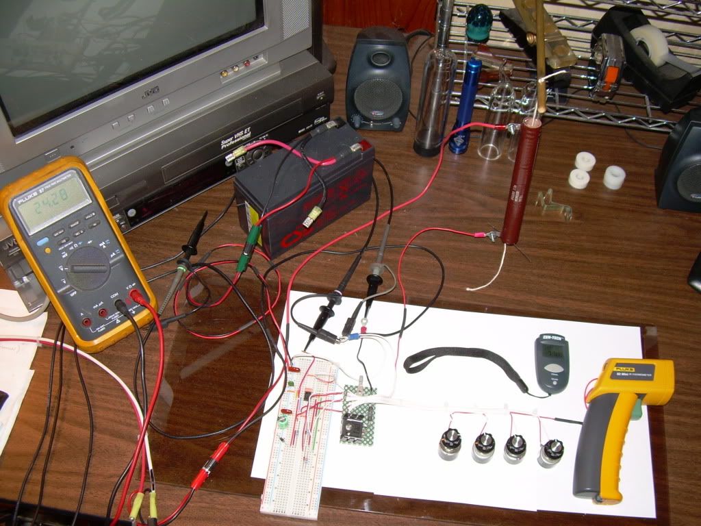
                            Replication Components -

                            1) International Rectifier - IRFPG50 HEXFET® Power MOSFET
                            w/ Sil-Pad insulator between Mosfet and Heat Sink

                            2) Fairchild Semiconductor - NE555N Timer

                            3) Vishay Spectrol - SP534 Percision Potentiometer/ 10-turn 2-Watt

                            4) Exide Technologies Battery "Liquid Lead Acid" Model # GT-H - TRACTOR 12V 12Ah CCA 235

                            5) CSB Battery Company "Gel Lead Acid" #GP 1270 F2 / 12 Volt 7.0 Ah

                            6) Test Load Resister "MEMCOR" #FR100 - 10 ohm + - 5%, 100 watt, 20 to 26 uH


                            Temperature Measurements -

                            Fluke 62 "mini" IR Themometer ( used maximum reading on each componenet )

                            Digital Mulit Meter -

                            Fluke 87 DMM true RMS

                            -------------------------------------------------------------------------

                            Channel 1 - Mosfet shunt
                            Channel 3 - 555 Timer pin #3
                            Channel 4 - 24 VDC "Liquid" Lead Acid Battery Bank


                            2us Start
                            *Original 2us "Start" .XLR Spread Sheet File
                            Original 2us_start .CSV file


                            20us Start
                            * Original 20us "Start" .XLR Spread Sheet File
                            Original 20us_start .CSV file


                            2us Finish
                            * Original 2us "Finish" .XLR Spread Sheet File
                            Original 2us_finish .CSV file


                            20us Finish
                            * Original 20us "Finish" .XLR Spread Sheet File
                            Original 20us_finish .CSV file


                            TEMPERATURE DATA -


                            200ns 555 OFF


                            40ns 555 ON


                            Glen
                            Last edited by FuzzyTomCat; 10-05-2009, 08:35 PM. Reason: added .XLR files
                            Open Source Experimentalist
                            Open Source Research and Development

                            Comment


                            • FUZZY That's just so FANTASTIC. A new bench mark in data capture. WOW. Many many thanks for this. And it's now really, really late. You need your sleep.

                              Comment


                              • AWESOME stuff there tomcat !!!!

                                Comment

                                Working...
                                X