Announcement

Collapse
No announcement yet.

COP 17 Heater | Rosemary Ainslie

Collapse
This topic is closed.
X
This is a sticky topic.
X
X
 
  • Filter
  • Time
  • Show
Clear All
new posts

  • Originally posted by Harvey View Post
    While looking for an envelope value that can be used for extrapolation (which seems to be 134.4µs in the 40µs/div data), I see that the visual presented shows a triple harmonic that is not present in the data.

    At first glance, it looks like periodic sets, but at closer examination it can be seen that distance between harmonics is widening as time progresses. It concerns me that this information is not included in the data, as it is my understanding that the visuals (scope shots) are generated by the scope digitally.

    Perhaps those are artifacts caused by image compression during the upload to the internet?

    If they are real, and not in our data, it may interfere with being able to extrapolate over long periods as I said could be done for the 7 hour run. Also, we wouldn't know mathematically if they impact our calculations in a positive or negative way.

    I'll see if I can grab the scope shot and point out what I am referring to here.

    Larger Pic

    Hi Harvey,

    Those two images the 40us and the 20us is part of the wave form oscillation light show from the TDS 3054C, it gets washed out some with the white screen background in the .PNG's small data file ..... much more impressive in person with the black background and I'm unable to change it, so it looks missing but no parts really are missing ....

    Glen
    Open Source Experimentalist
    Open Source Research and Development

    Comment


    • Rosemary Ainslie COP>17 Heater Circuit - TEST #4

      Hi everyone,

      Here is a replication of TEST #3 with three (3) sets of images and data dumps taken seven times one set every hour for six hours plus temperature readings every 15 minutes.

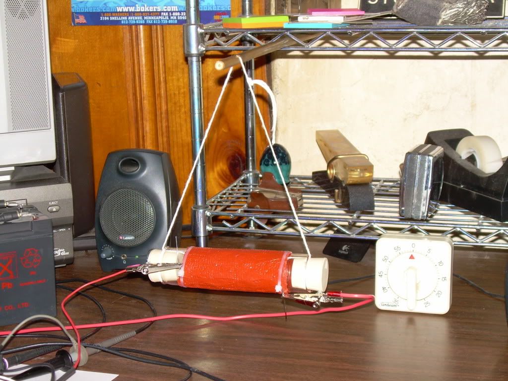
      The Load Prototype "Quantum" 10 ohm resistor was mounted horizontal with two (2) size #5-1/2 rubber stoppers inserted in each end, elevated 3" from the desk surface.


      TEST #4

      Rosemary Ainslie COP>17 Heater Circuit
      "Quantum" October 2002

      Replication Components -

      1) International Rectifier - IRFPG50 HEXFET® Power MOSFET
      w/ Sil-Pad insulator between Mosfet and Heat Sink

      2) Fairchild Semiconductor - NE555N Timer

      3) Vishay Spectrol - SP534 Percision Potentiometer/ 10-turn 2-Watt

      4) Exide Technologies Battery "Liquid Lead Acid" Model # GT-H - TRACTOR 12V 12Ah CCA 235

      5) CSB Battery Company "Gel Lead Acid" #GP 1270 F2 / 12 Volt 7.0 Ah

      6) Prototype "Quantum" Load Resister 10 ohm + - 1%

      7) Shunt Resistor - "Dale" RS-2B 0.25 ohm, 3 watt, 3 %


      Temperature Measurements -

      Fluke 62 "mini" IR Themometer ( used maximum reading on each componenet )

      Digital Mulit Meter -

      Fluke 87 DMM true RMS


      START

      1_40us_520V-01_10_08_09.xlr Spread Sheet File
      1_40us_520V-01_10_08_09.png Image File


      1_20us_520V-01_10_08_09.xlr Spread Sheet File
      1_20us_520V-01_10_08_09.png Image File
      1_2us_520V-01_10_08_09.xlr Spread Sheet File
      1_2us_520V-01_10_08_09.png Image File


      HOUR 2

      2_40us_520V-01_10_08_09.xlr Spread Sheet File
      2_40us_520V-01_10_08_09.png Image File


      2_20us_520V-01_10_08_09.xlr Spread Sheet File
      2_20us_520V-01_10_08_09.png Image File
      2_2us_520V-01_10_08_09.xlr Spread Sheet File
      2_2us_520V-01_10_08_09.png Image File


      HOUR 3

      3_40us_520V-01_10_08_09.xlr Spread Sheet File
      3_40us_520V-01_10_08_09.png Image File


      3_20us_520V-01_10_08_09.xlr Spread Sheet File
      3_20us_520V-01_10_08_09.png Image File
      3_2us_520V-01_10_08_09.xlr Spread Sheet File
      3_2us_520V-01_10_08_09.png Image File


      HOUR 4

      4_40us_520V-01_10_08_09.xlr Spread Sheet File
      4_40us_520V-01_10_08_09.png Image File


      4_20us_520V-01_10_08_09.xlr Spread Sheet File
      4_20us_520V-01_10_08_09.png Image File
      4_2us_520V-01_10_08_09.xlr Spread Sheet File
      4_2us_520V-01_10_08_09.png Image File


      HOUR 5

      5_40us_520V-01_10_08_09.xlr Spread Sheet File
      5_40us_520V-01_10_08_09.png Image File


      5_20us_520V-01_10_08_09.xlr Spread Sheet File
      5_20us_520V-01_10_08_09.png Image File
      5_2us_520V-01_10_08_09.xlr Spread Sheet File
      5_2us_520V-01_10_08_09.png Image File


      HOUR 6

      6_40us_520V-01_10_08_09.xlr Spread Sheet File
      6_40us_520V-01_10_08_09.png Image File


      6_20us_520V-01_10_08_09.xlr Spread Sheet File
      6_20us_520V-01_10_08_09.png Image File
      6_2us_520V-01_10_08_09.xlr Spread Sheet File
      6_2us_520V-01_10_08_09.png Image File


      FINISH - END OF TEST

      7_40us_520V-01_10_08_09.xlr Spread Sheet File
      7_40us_520V-01_10_08_09.png Image File


      7_20us_520V-01_10_08_09.xlr Spread Sheet File
      7_20us_520V-01_10_08_09.png Image File
      7_2us_520V-01_10_08_09.xlr Spread Sheet File
      7_2us_520V-01_10_08_09.png Image File

      TEMPERATURE DATA -


      All Images and data from the Tektronix TDS 3054C from the Tektronix Corporation


      Glen
      Open Source Experimentalist
      Open Source Research and Development

      Comment


      • Hi Fuzzy. So many thanks for all this hard work. I'm blown away. There seems to be a difference in the two waveforms between these two tests. Here's my take - and from a rank amateur and as best I can describe the 'harmonics' - I think is the term. The previous looks like a tower at the edge of lake with the sun rising north, north east behind the tower - which throws a long shadow of the tower into water. This last waveform? Is that the same? Harvey, someone - can you check on this? I don't know how to make a graph of the wider sample range.

        EDIT I'm referring to the source shunt - blue trace?

        But thank you Fuzzy. Yet again. You threatened you'd keep us busy and indeed you are. Cannot tell you how impressed we all are.

        Last edited by witsend; 10-09-2009, 11:29 PM. Reason: Hope I've done the edit right

        Comment


        • Glen, this is really good work Your documentation of the tests are impeccable.

          I got up around 6:00AM (after retiring at 2:30AM) just to check the results. I DL'd several of the files, from hour 1, 6 & 7 and did the quick ballpark averages.

          It would appear that the battery average drops by about a volt over the test period, and the average battery power delivered also drops by the end as does the Ohmic treatment for Load Power.

          My quick calcs showed ~12W at the beginning dropping to ~10W battery delivery power by the end. The Ohmic treatment for Load Power is over 600W - very similar to your previous run. But the increase in Battery delivery power seems to indicate that we have slipped out of the efficient operation you presented before. I still have to evaluate the caloric significance in both tests.

          Some have expressed concerns regarding the 600+W Ohmic, and the 165+W phase shifted values as being too great, and I agree they are. Not yet included in any of my calcs are the inductive and capacitive reactance effects of the load circuit. Rosemary did ask if I could calculate that for the pulse period - just grabbing an arbitrary inductance value of 14µH (I really don't recall the number we had before for those windings), along with 400ns spike cycle width, I very loosely determined a 219Ω inductive impedance in the load during that period. Real inductance would be needed to correctly value this. And of course that impedance changes during the periods that activity is not so narrow. And likewise, there is a capacitive reactance involved as well. I was explaining to Rosemary, that that value can be very dynamic in a flexible coil arrangement due to the magnetic interactions of the windings. As the spacing between the windings changes, so does the capacitance - it is all very small, but does impact the impedance. So the impedance plays a big part in bringing those high values down to the 17W that Rosemary's first team documented.

          There seems to be two obvious differences in the test procedure that may have been responsible for the increase from around 1W battery power to 12W battery power. The first is the very clear aperiodic operation. I have seen the duty cycle climb to ~90% in this mode on my rig for parts of the period. It would seem that your somewhat periodic operation from the last run provided a leaner and cleaner result The second, although visibly obvious, the actions may be a bit more subtle - that is the closed resistor. As resistive materials increase in temperature, they also increase in resistance. This is a self regulating feature of this particular circuit, but it may open some insight as to how the energy flow interacts. MH's chimney arrangement provided a continuous convection of new cool air to chill the resistor. It's effect is evident in the temperature readings that shows a clear cyclic heating and cooling. As the resistor cools, the convection stops, then as it heats it starts up again. I have to give the implications some thought as to how the disallowed dissipation of the horizontal plugged version steals from the battery recharge - very counter intuitive, but may be related to the phase shift of the current in some way. The results were unexpected.

          I need a way to relate the caloric values to the power. I don't think its possible to accurately map the resistor itself based on material dissipation characteristics and surface area. I think the base line test is probably the best approach in this regard. Accurately mapping the specific resistor for a given applied power , which should not matter if it is AC or DC except for the aforementioned reactance. It would be interesting to run the resistor on a straight 2.5MHz sine wave and see the thermal footprint.

          We are all greatly indebted to the painstaking efforts you have put into this thus far and I for one would like you to know how much it is appreciated

          One thing I want to stress here, even though we are seeing a marked increase in battery delivery power over the last test, it does not mean the system is not operating at a COP > 1. The Ohmic treatment is 65:1 and that 65 gets reduced by the phase shift and reactance - how much? I bet MH could math it out better than me

          I just had an idea for a floating FET recovery switch, I need to write this down before I forget it...

          "Amy Pond, there is something you need to understand, and someday your life may depend on it: I am definitely a madman with a box." ~The Doctor

          Comment


          • Please investigate what Otto posted in Oveunity.com thread Steven Marks secret

            Seems that I was right, ground of signal generator should not be connected with battery connected to FET and heating resistor-inductor. Negative impulses are also used.

            Just read this thread

            Comment


            • Originally posted by boguslaw View Post
              Please investigate what Otto posted in Oveunity.com thread Steven Marks secret

              Seems that I was right, ground of signal generator should not be connected with battery connected to FET and heating resistor-inductor. Negative impulses are also used.

              Just read this thread
              Which thread? Link?

              EDIT:
              NM read it.
              Last edited by Harvey; 10-10-2009, 09:51 AM.
              "Amy Pond, there is something you need to understand, and someday your life may depend on it: I am definitely a madman with a box." ~The Doctor

              Comment


              • Looking at the possible effects of inductive impedance combined with current lag (phase angle of voltage to current):

                Excel Data Analysis

                I bet there is some enterprising young programmer that could build a java interface to do this , but us old farts just look at the numbers and graphs.

                Cheers,

                Harvey
                "Amy Pond, there is something you need to understand, and someday your life may depend on it: I am definitely a madman with a box." ~The Doctor

                Comment


                • Happenstance

                  Guys - here's a synchronous event that has to defy the odds. 10 years ago when I was trying to put this circuit together I knew nothing about inductance - resistance - or indeed anything much. I was looking for a resistor and simply shopped for the biggest diameter with the thickest wire that I could find. I think Harvey mentioned that this is usually his criteria for grocery shopping. Back then all I wanted to do was generate as much counter electromotive force as I could and - big seemed better.

                  Then the results - that crowded in around this were unarguable and widely accredited. But still - wherever it was advanced on any theoretical basis it was met with scepticism - notwithstanding the evidence which then was still demonstrable. I was entirely unable to advance the technology.

                  Then, on these forums the same thing. Rank scepticism - and more of it - and only small evidence of gains. Then Fuzzy made his own resistor and used the only reliable criteria available being the diameter of his resistor. The wire, the windings and the rest of it were developed on a 'best guess' basis. But his resistor seems to have cracked that elusive barrier. I am wondering if the effect needs that wide space inside the coil and somehow - hamper this - and the effect goes away.

                  Just a thought. If so, then it's no wonder that the benefits here have eluded detection and for so long. And then too, it would explain the rank disbelief that was the unhappy reaction to our own claims. Perhaps Fuzzy can explore a resistor with a smaller diameter and check if this can reach that same optimised performance.

                  Comment


                  • Hi Rosemary,

                    It is an interesting thing to evaluate - the coil diameter.

                    The formula for determining the inductance of a single layer air core coil is L = (r˛N˛)/(9r + 10l)

                    This places r˛ over 9r. This is interesting because as r increases we find that we eventually approach a value that nets to 1 (81/81). That value is 9. In other words, it would seem that when the coil equals 18" in diameter (9r), the inductance formula would simply becomes the number of turns squared (N˛) divided by 10 times the length (10l). In fact, r˛ over 9r simply resolves to a percentage of 9. For instance, if r were 2.25", then the factor would be 1/4 (0.25) or 2.25 divided by 9 because 2.25 is one fourth of 9.

                    But that would be too simple. Algebraically we flavor the equation by multiplying the numerator of this factor by the number of turns while adding the denominator to 10 times the length. So even though we see r˛ divided by 9r, we cannot reduce it as I have indicated above. (81 x N˛) / (81 + 10l) is not the same thing as (1 x N˛) / (1 + 10l). But we do get a feel here for how the radius impacts the inductance.

                    Let's make things easy - let's say we have a 1 turn coil, 1 inch long. Now N˛ = 1 and 10l = 10 *1. Now lets see how different radii impact the inductance. First we'll choose a radius of 2.25"... L = 0.17µH . Now let's try 4.5"... L=0.4µH. Now let's try 6.75" ... L = 0.64µH and so on. So increasing the diameter, increases the inductance. How does the number of turns and length effect it? The length decreases the inductance, while the number of turns increases the inductance.

                    Interestingly, a radius of 20" and a length of 2" always works out to have an inductance of 2(N˛). But that is a big ask coil. I know I wouldn't ask for a 40" diameter coil...ok, maybe I would - depending on what I was doing.

                    Now the inductive reactance is simply 2πfL so clearly as the inductance increases and the frequency increases, the reactance increases. This is why a length of resistive wire plugged into the mains doesn't melt in two when coiled where it would if it were straight - all based on the inductance and the mains frequency (50 - 60 Hz).

                    Now I pose an interesting question for our readers:
                    Is the inductive reactance a product of the frequency or the rate of change of voltage and current? To illustrate the question better, lets compare two different waveforms. First, a continuous cyclic sinus waveform of a given frequency. We will say, that this wave form passes through zero 120 times per second (60Hz) and is always in transition, a perfect sine wave. Second, we will take that same waveform, but we will bunch it up so that the cycle completes in 1/10 of the time, but we still wait before issuing another cycle so that the frequency is still 60Hz. We still only get 60 cycles in a second, its just a quick pulse and then some flat time before the next one. Since frequency is a count of how many cycles we have in a period, does the second waveform change our formula 2πfL? Or do we need to shift our definition of frequency to mean how wide the cycle itself is (dV/dt) rather than how many their are in a period?

                    We already understand this difference when dealing with electromagnetic wave propagation like light and radio. We quickly determine the frequency based on the wavelength of a single cycle and have developed different sorts of vernacular to describe the second example above - such as single cycle burst, burst frequency etc. We even have DTMF, dual tone multi frequency common in telephony. But for some reason, when we get into power systems where we begin thinking of current as a flow of particles, i.e. electrons, the concept gets a bit muddied.

                    I draw attention to this matter, because the RA circuit power is in fact a member of the second example. While the quantity of high voltage spikes may arrive at a frequency in kHz, the actual frequency of the spike is in the MHz, and that changes the calculations for inductive reactance.


                    Last edited by Harvey; 10-11-2009, 10:22 PM. Reason: left out 10 *
                    "Amy Pond, there is something you need to understand, and someday your life may depend on it: I am definitely a madman with a box." ~The Doctor

                    Comment


                    • Now I would like to address the matter of optimizing the RA circuit.

                      There are several factors to consider.

                      First, the FET output capacitance. This plays a part in the resonant frequency with the inductor. A quick look at a nomograph shows that for 250pF and the quoted 8µH inductance a resonant frequency would develop around 3MHz. In FTC's case, the data seems to point at around 2MHz. Different FET's can have different output capacitance.

                      Another factor closely related to the first is the internal capacitance of the inductor. This is caused by the windings being parallel to each other with a dielectric (even air) between them. Each winding appears as a curved capacitor plate to its neighbor with a resistor between the plates. So that internal capacitance can shift the resonant frequency accordingly. It also has an effect on the phase angle of current and voltage running through the inductor.

                      Next we need to consider how much energy the inductor can store as a magnetic field.

                      This is how Descartes viewed the magnetic field as drawn in 1644. Of course Peregrinus had already mapped the magnetic field of a sphere magnet in 1289 AD. So the knowledge that magnetic fields exist have been with us for many centuries. But it wasn't until the 1800's that we were able to get a glimpse of the energy storage nature of the magnetic field. Poisson gave us this accurately even though his theory was inverted. Translating those equations to our use here we arrive at E = ˝LI˛ where E is Joules, L is henries and I is amperes. It is easy to see if we want a classical treatment of the energy output we will need a greater inductance. This can put us in the unsavory position of having to decide if we want frequency or brute power. That brings us to our next consideration.

                      Where does the 'heat' come from? How do we get 'more'? This is really the heart of the matter. Classical treatment simply tells us to evaluate the power dissipated in the resistance. Good idea...what power? Voltage time Current = Power (P=EI) [E stands for Electromotive Force which is a fancy term for Voltage] . So the lazy way out is to just figure Battery Voltage across Circuit resistance. In the RA power circuit this is 24V / 12.25 Ohms [10 for the load, 2 for the FET and 0.25 for the 'shunt]. So, Timer on - we get 1.96A which translates to 47W ... for 15µS every 400µS, or about 1.76W/s with a duty cycle of ~3.7%. So if measure 17W of worth of heat then one of these things must occur. Either extra energy is supplied from outside the conventional circuit, or the duty cycle must increase or both. Or the phase angle in the inductor must change such that the magnetic energy stored there can be used to produce heat. How much could we expect to get back from the field if we brought it all back in phase? Would you believe 16.6µJ ? Yep, even for 100% duty cycle the field will only store 16.6 micro joules of energy for the 8.64µH inductor - that's what I calculate using the above formula, but it seems really low - anyone care to double check that for me? So where are the 520V spikes coming from? Well either they have extremely low power, or the power they do have needs to be described by non-classical means. Why do I say this? Because when they are present, the classical flow of energy has stopped. They are the full product of the magnetic field. Rosemary's hypothesis was that in this mode, a secondary source of energy is disturbed and that source allows energy to flow into the circuit adding to the voltage spike. But that energy needs to be in phase to produce heat in the resistor. Another matter, is dielectric heating. This can occur when the coil is operated above 10MHz and does not necessarily require the current to be in phase with the voltage. All that is needed there is a potential capable of stressing the material that frequency.

                      So, it would seem that the inductance plays a much bigger role in generating high frequency magnetic perturbations than storing up energy to be released later while the FET is off.

                      What are your thoughts on the matter?

                      "Amy Pond, there is something you need to understand, and someday your life may depend on it: I am definitely a madman with a box." ~The Doctor

                      Comment


                      • Rosemary Ainslie COP>17 Heater Circuit - TEST #5

                        Hi everyone,

                        This is a repeat attempt of the results on TEST #3 with some new data which may surprise everyone but maybe not ...


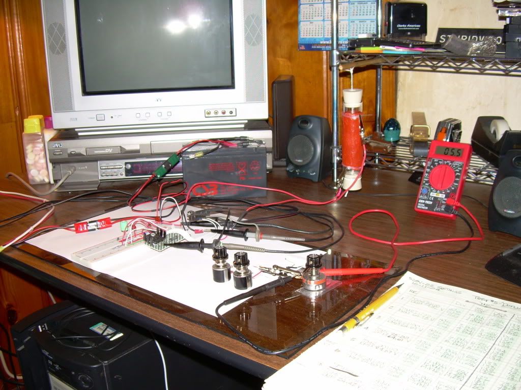
                        The Load Prototype "Quantum" 10 ohm resistor was mounted vertical with two (2) size #5-1/2 rubber stoppers inserted in each end, elevated 3" from the desk surface.


                        TEST #5

                        Rosemary Ainslie COP>17 Heater Circuit
                        "Quantum" October 2002

                        Replication Components -

                        1) International Rectifier - IRFPG50 HEXFET® Power MOSFET
                        w/ Sil-Pad insulator between Mosfet and Heat Sink

                        2) Fairchild Semiconductor - NE555N Timer

                        3) Vishay Spectrol - SP534 Percision Potentiometer/ 10-turn 2-Watt

                        4) Exide Technologies Battery "Liquid Lead Acid" Model # GT-H - TRACTOR 12V 12Ah CCA 235

                        5) CSB Battery Company "Gel Lead Acid" #GP 1270 F2 / 12 Volt 7.0 Ah

                        6) Prototype "Quantum" Load Resister 10 ohm + - 1%

                        7) Shunt Resistor - "Dale" RS-2B 0.25 ohm, 3 watt, 3 %


                        Temperature Measurements -

                        Fluke 62 "mini" IR Themometer ( used maximum reading on each componenet )

                        Digital Mulit Meter -

                        Fluke 87 DMM true RMS

                        ************************************************** *******

                        Channel 1 - Mosfet source shunt
                        Channel 2 - Mosfet drain
                        Channel 3 - 555 Timer pin #3
                        Channel 4 - 24 VDC "Liquid" Lead Acid Battery Bank


                        START

                        1_40us_520V-02_10_11_09 .png Image File
                        1_40us_520V-02_10_11_09 .xlr Spread Sheet File


                        1_20us_520V-02_10_11_09 .png Image File
                        1_20us_520V-02_10_11_09 .xlr Spread Sheet File
                        1_2us_520V-02_10_11_09 .png Image File
                        1_2us_520V-02_10_11_09 .xlr Spread Sheet File


                        HOUR 2


                        2_40us_520V-02_10_11_09 .png Image File
                        2_40us_520V-02_10_11_09 .xlr Spread Sheet File


                        2_20us_520V-02_10_11_09 .png Image File
                        2_20us_520V-02_10_11_09 .xlr Spread Sheet File
                        2_2us_520V-02_10_11_09 .png Image File
                        2_2us_520V-02_10_11_09 .xlr Spread Sheet File


                        HOUR 3


                        3_40us_520V-02_10_11_09 .png Image File
                        3_40us_520V-02_10_11_09 .xlr Spread Sheet File


                        3_20us_520V-02_10_11_09 .png Image File
                        3_20us_520V-02_10_11_09 .xlr Spread Sheet File
                        3_2us_520V-02_10_11_09 .png Image File
                        3_2us_520V-02_10_11_09 .xlr Spread Sheet File


                        HOUR 4


                        4_40us_520V-02_10_11_09 .png Image File
                        4_40us_520V-02_10_11_09 .xlr Spread Sheet File


                        4_20us_520V-02_10_11_09 .png Image File
                        4_20us_520V-02_10_11_09 .xlr Spread Sheet File
                        4_2us_520V-02_10_11_09 .png Image File
                        4_2us_520V-02_10_11_09 .xlr Spread Sheet File


                        HOUR 5


                        5_40us_520V-02_10_11_09 .png Image File
                        5_40us_520V-02_10_11_09 .xlr Spread Sheet File


                        5_20us_520V-02_10_11_09 .png Image File
                        5_20us_520V-02_10_11_09 .xlr Spread Sheet File
                        5_2us_520V-02_10_11_09 .png Image File
                        5_2us_520V-02_10_11_09 .xlr Spread Sheet File


                        HOUR 6


                        6_40us_520V-02_10_11_09 .png Image File
                        6_40us_520V-02_10_11_09 .xlr Spread Sheet File


                        6_20us_520V-02_10_11_09 .png Image File
                        6_20us_520V-02_10_11_09 .xlr Spread Sheet File
                        6_2us_520V-02_10_11_09 .png Image File
                        6_2us_520V-02_10_11_09 .xlr Spread Sheet File


                        FINISH


                        7_40us_520V-02_10_11_09 .png Image File
                        7_40us_520V-02_10_11_09 .xlr Spread Sheet File


                        7_20us_520V-02_10_11_09 .png Image File
                        7_20us_520V-02_10_11_09 .xlr Spread Sheet File
                        7_2us_520V-02_10_11_09 .png Image File
                        7_2us_520V-02_10_11_09 .xlr Spread Sheet File


                        TEMPERATURE DATA-


                        ADDED WAVE FORMS -


                        1us_520V-02_10_11_09 .png Image File
                        400ns_520V-02_10_11_09 .png Image File
                        200ns_520V-02_10_11_09 .png Image File


                        All Images and data from a Tektronix TDS 3054C from the Tektronix Corporation


                        Glen
                        Last edited by FuzzyTomCat; 10-13-2009, 05:26 PM. Reason: tired -grammer - channel info
                        Open Source Experimentalist
                        Open Source Research and Development

                        Comment


                        • Power Circuit Anislie

                          Hi all,

                          Just a little input of a circuit for power output, excuse the pun.

                          This is part of what I am working on and I thought that someone would like to try this.

                          I have been testing this and I am getting some very good results. I think that with some tuning on the pots of the 555 circuit you will be able to send charge back to the battery and power a 220v 20w bulb.

                          I am not using the same FET as I do not have one at the moment and the triggering circuit is different, but the basic idea will be sound for the circuit of Rosemary.

                          I am away for a week doing an exhibition and so I can not test more at the moment but I can light a 20w, 220v bulb to full brightness and send power back to the battery.

                          Will check in when I can in the next week, all keep up this very good work

                          Mike
                          Attached Files

                          Comment


                          • FUZZY I held back comment so that I could do some numbers on your data dumps. You've excelled here. It intrigues me that the waveform - oscillations and harmonics seem to vary throughout the test period. But all variations seem to point to extraordinary gains. Frankly I want Harvey to confirm the values and post the official results from this. Do not trust my talents and nor have I managed to open all the files.

                            I notice that your resistor is again hung? I get it that this is preferred as there is less evident rf. MH may very well feel vindicated here - lol. In which case we will likely get another slew of posts.

                            But all I can give you is praise. The collation of this data is complex and clearly handled by the master. We are all blown away by the expertise here and truly indebted - on so many levels.

                            And it is indeed interesting that Stefan has reserved all comment on these results. Rather strange?

                            Anyway Fuzzy - this is getting repetitive but it's a repetition that I thoroughly enjoy. WELL DONE YET AGAIN. And THANK YOU THANK YOU THANK YOU.

                            Comment


                            • Originally posted by Groundloop View Post
                              @Witsend,

                              My contribution so far has been using time and money to make PCBs
                              for the circuit. I guess Luc still has some left?

                              My time is limited and I can't promise any extensive testing. The Tektronix o-scope is way out of my reach. It costs in excess of 100.000,- NOK.

                              Alex (Groundloop)
                              Hi Alex and all,

                              still have many of the boards left so don't be shy just email me your address at: gotoluc@yahoo.com to receive your FREE board.

                              Keep up all the great work

                              Luc

                              Comment


                              • Rosemary Ainslie COP>17 Heater Circuit - TEST #5

                                Hi everyone,

                                Here is a "YouTube" video of Test #5 "FINISH" the last of recording of Images and Data at 40us, 20us and 2us divisions of the 6 hour test with circuit set up and additional wave forms included ......

                                Rosemary Ainslie COP>17 Heater Circuit - TEST #5 - Image and Data Recording

                                Rosemary Ainslie COP17 Heater Circuit - TEST #5 - Image and Data Recording - Complete - with Set Up and Additional Wave Forms


                                Enjoy !!
                                Glen


                                ------------------------------------------------------------------------
                                EDIT - Added Image and Data Recording - Complete - with Set Up and Additional Wave Forms Video
                                Last edited by FuzzyTomCat; 10-15-2009, 12:55 AM. Reason: added video
                                Open Source Experimentalist
                                Open Source Research and Development

                                Comment

                                Working...
                                X