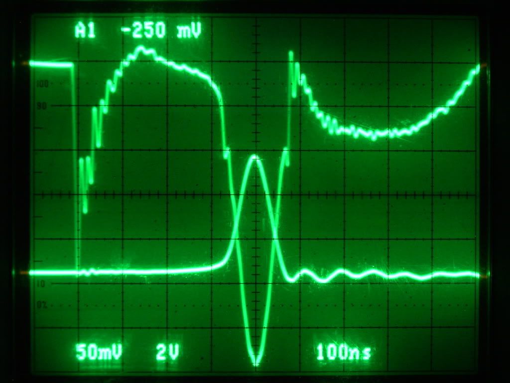
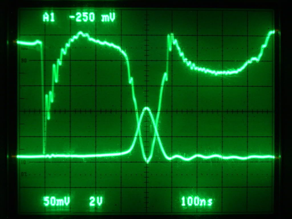
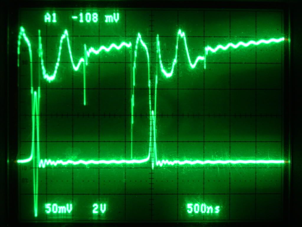
Announcement

Collapse
No announcement yet.

COP 17 Heater | Rosemary Ainslie

Collapse
This topic is closed.
X
This is a sticky topic.
X
X
 
  • Filter
  • Time
  • Show
Clear All
new posts

  • Hi All,

    It has been a long day for me, but I did want to post up the results for the Battery Power Averages for the last 21 sample files:

    Code:
    Battery Power AVG
    Hour	2µs		20µs		40µs
    1	1.514827571	-2.479456000	 1.500064000
    2	-3.205999153	-4.045888000	-5.239488000
    3	-5.533148312	-5.207520000	-1.636576000
    4	-2.350759808	-1.969696000	-3.160768000
    5	-2.070294717	-3.493984000	-4.054848000
    6	-1.257904431	-4.098176000	-2.052608000
    7	-2.550643907	-4.765152000	-3.565344000
    
    AVG	-2.207703251	-3.722838857	-2.601366857
    I think it is important at this point to mention the level of precision involved. As the time base is reduced the precision increases. The 40µs/div data is only accurate to TWO decimal places even though my calcs are carried out to 9. For example, hour 2, 40µs above should be read as no more accurate than -5.24V AVG

    I do not have the original CSV files, but instead I have the XLR files that Glen uploaded for the 2µs & 20µs data. I need to check with him on the actual precision for those data dumps.

    The wide variance in average voltage between dumps in the same hour points to missing data in between the collection times and I have asked for at least one hour to be taken at 1/10th HR increments (6min). We may have to keep increasing this resolution until we can establish with confidence, the limits of the deviations above and below zero.

    The preliminary treatment of this data indicates that out of 21 different sample sets comprised of 10000 individual samples for each set, with a time period of 2, 20 and 40 microseconds respectively, the battery delivery power is negative 90.5% of the time on the average.

    Time was spent to ensure that the method of averaging was an accurate means of integrating the data. Because of the varied waveform the integration must be approximate because the y function would be too complex to consider within the scope of this endeavor. However, the Midpoint Rule seems adequate where each sample voltage represents the y value at midpoint. The difference between an actual area integration and the general averaging was negligible in the one sample I did over Aarons similar data. Readers with more accurate integration tools may wish to import the data and verify that this is the case. It is undetermined whether or not another rule, such as the Trapezoidal rule, could be a more accurate method of integrating this particular complex waveform.

    When baselines are established for these resistors that give us a means to compare the caloric values to the power needed to produce those values, then we will be in position to compare these battery readings to the output power. A cursory approach on a single sample intimated that the load resistor is operating at a total impedance of ~23.33 ohms with a 90° phase shift in current. This arrangement allows a voltage spike of 522V to produce a negative battery power of 358.4W (See Row 18 of Hour 1 20µs - The current is considered shifted to 90° lag at row 23)

    It should be noted, that the average battery voltage seems to decline over the seven hour period by a small amount. It is noteworthy that if the events were truly negative throughout the entire period 90.5% of the time, the battery should recharge instead of discharging. I am willing to accept that there may be extenuating circumstances in this circuit that prevent this from happening in some way. I am encouraged by the repeatability of this effect in 3 different locations.

    It may be necessary, to provide an external HDD to be used for realtime data dumps at close resolutions during a 1 hour run. I don't know if the equipment in use can provide that seamless flow or not. As we close in on this tighter, it does appear that the efficiency of this circuit is quite high.

    "Amy Pond, there is something you need to understand, and someday your life may depend on it: I am definitely a madman with a box." ~The Doctor

    Comment


    • Amazing work Guys. And to get it all done on a shoe string budget and spare time Am preserving all your hard work so every one does not get tired fingers Thanks so much Aaron Harvey and Glen.
      Last edited by ashtweth; 10-15-2009, 05:19 AM.

      Comment


      • battery charge

        Originally posted by Harvey View Post
        It should be noted, that the average battery voltage seems to decline over the seven hour period by a small amount. It is noteworthy that if the events were truly negative throughout the entire period 90.5% of the time, the battery should recharge instead of discharging. I am willing to accept that there may be extenuating circumstances in this circuit that prevent this from happening in some way.
        The bigger low impedance batteries are too much of a sink to get a push in voltage. I've seen the same thing. But several times that I put the same setup right over to the gel cells, the voltage did indeed climb up a a few hundred's and maintained that for hours before coming back down again.
        Sincerely,
        Aaron Murakami

        Books & Videos https://emediapress.com
        Conference http://energyscienceconference.com
        RPX & MWO http://vril.io

        Comment


        • A Belated Tribute To Your Hard Work

          Originally posted by ashtweth View Post
          Amazing work Guys. And to get it all done on a shoe string budget and spare time Am preserving all your hard work so every one does not get tired fingers Thanks so much Aaron Harvey and Glen.
          Ash, I've gone to some trouble to thank our key players and have never given due tribute to your own efforts here. Let me see if I can fix that.

          The thread is already crowding into 3000 odd posts and it's barely 5 months old. That's a lot of writing and based on a mountain of data. That we have you to carefully sift through the relevant from the nonsense, and to keep everything accurately archived - is acknowledged with an onerous sense of gratitude. It has got to be the most critical and possibly the most challenging of all the tasks related to this. Truly monumental. And clearly in the most capable of hands. Thank you Ash for all this wonderful work. Thank goodness we can rely on your unerring eye for the pertinent. If nothing comes of this I take it that it was a labour of love and therefore not entirely a waste of effort. And if anything does result from this - then it will all be of some historical significance. Love's labour won.

          You are our truly our librarian and well qualified as such. Many - many thanks. Much appreciated - I know this - by all of us.


          Rosie
          Last edited by witsend; 10-15-2009, 06:44 AM.

          Comment


          • Originally posted by Harvey View Post
            Hi All,
            ...
            I think it is important at this point to mention the level of precision involved. As the time base is reduced the precision increases. The 40µs/div data is only accurate to TWO decimal places even though my calcs are carried out to 9. For example, hour 2, 40µs above should be read as no more accurate than -5.24V AVG

            I do not have the original CSV files, but instead I have the XLR files that Glen uploaded for the 2µs & 20µs data. I need to check with him on the actual precision for those data dumps.

            The wide variance in average voltage between dumps in the same hour points to missing data in between the collection times and I have asked for at least one hour to be taken at 1/10th HR increments (6min). We may have to keep increasing this resolution until we can establish with confidence, the limits of the deviations above and below zero.

            The preliminary treatment of this data indicates that out of 21 different sample sets comprised of 10000 individual samples for each set, with a time period of 2, 20 and 40 microseconds respectively, the battery delivery power is negative 90.5% of the time on the average.

            Time was spent to ensure that the method of averaging was an accurate means of integrating the data. Because of the varied waveform the integration must be approximate because the y function would be too complex to consider within the scope of this endeavor. However, the Midpoint Rule seems adequate where each sample voltage represents the y value at midpoint. The difference between an actual area integration and the general averaging was negligible in the one sample I did over Aarons similar data. Readers with more accurate integration tools may wish to import the data and verify that this is the case. It is undetermined whether or not another rule, such as the Trapezoidal rule, could be a more accurate method of integrating this particular complex waveform.

            When baselines are established for these resistors that give us a means to compare the caloric values to the power needed to produce those values, then we will be in position to compare these battery readings to the output power. A cursory approach on a single sample intimated that the load resistor is operating at a total impedance of ~23.33 ohms with a 90° phase shift in current. This arrangement allows a voltage spike of 522V to produce a negative battery power of 358.4W (See Row 18 of Hour 1 20µs - The current is considered shifted to 90° lag at row 23)

            It should be noted, that the average battery voltage seems to decline over the seven hour period by a small amount. It is noteworthy that if the events were truly negative throughout the entire period 90.5% of the time, the battery should recharge instead of discharging. I am willing to accept that there may be extenuating circumstances in this circuit that prevent this from happening in some way. I am encouraged by the repeatability of this effect in 3 different locations.

            It may be necessary, to provide an external HDD to be used for realtime data dumps at close resolutions during a 1 hour run. I don't know if the equipment in use can provide that seamless flow or not. As we close in on this tighter, it does appear that the efficiency of this circuit is quite high.

            Thanks Harvey. All this hard work and close analysis speaks for itself. Also much appreciated. Just don't burn yourself out here. You're performing above and beyond and I just hope you can afford us all this time and effort.

            Comment


            • Rosemary Ainslie COP>17 Heater Circuit - TEST #6

              Hi everyone,

              I did a short test on the Rosemary Ainslie COP>17 Heater Circuit with a standard store bought 10 ohm 100 watt ( "MEMCOR" # FR100 ) load resistor, and after a short time the results were not as expected. The best arrangement for added gains in this circuit is to have the Mosfet source or Channel 1 to be the lowest mV as possible 30 to 70 is ideal but anything over 100 mV gains in circuit efficiency lowers.

              The "load resistor" temperature was higher but so was the consumption of battery energy loosing .3 Volts every hour on my Fluke 87 DMM connection.


              40us

              40us_STD_10ohm_10-14-09 .png Image File
              40us_STD_10ohm_10-14-09 .xlr Spread Sheet File


              20us

              20us_STD_10ohm_10-14-09 .png Image File
              20us_STD_10ohm_10-14-09 .xlr Spread Sheet File


              2us

              2us_STD_10ohm_10-14-09 .png Image File
              2us_STD_10ohm_10-14-09 .xlr Spread Sheet File


              10ms

              10ms_STD_10ohm_10-14-09 .png Image File
              10ms_STD_10ohm_10-14-09 .xlr Spread Sheet File


              100ns

              100ns_STD_10ohm_10-14-09 .png Image File


              All Images and data from a Tektronix TDS 3054C from the Tektronix Corporation


              Glen
              Last edited by FuzzyTomCat; 10-15-2009, 08:59 AM.
              Open Source Experimentalist
              Open Source Research and Development

              Comment


              • Fuzzy - thanks for this. I take it that - from these results that the smaller the diameter the resistor - the less evident the advantage of the switching system? Hopefully Aaron could corroborate this?

                Comment


                • Originally posted by witsend View Post
                  Ash, I've gone to some trouble to thank our key players and have never given due tribute to your own efforts here. Let me see if I can fix that.

                  The thread is already crowding into 3000 odd posts and it's barely 5 months old. That's a lot of writing and based on a mountain of data. That we have you to carefully sift through the relevant from the nonsense, and to keep everything accurately archived - is acknowledged with an onerous sense of gratitude. It has got to be the most critical and possibly the most challenging of all the tasks related to this. Truly monumental. And clearly in the most capable of hands. Thank you Ash for all this wonderful work. Thank goodness we can rely on your unerring eye for the pertinent. If nothing comes of this I take it that it was a labour of love and therefore not entirely a waste of effort. And if anything does result from this - then it will all be of some historical significance. Love's labour won.

                  You are our truly our librarian and well qualified as such. Many - many thanks. Much appreciated - I know this - by all of us.


                  Rosie
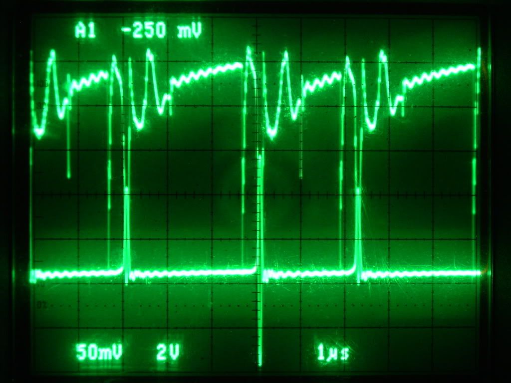
                  Whoa thanks a lot Rosie , i just try to pitch in my part and consider my self equal like ever one working together, its addictive being a community We are almost onto winding Glen's inductor for some more tests. Sorry we have not been able to contribute much technical but rest assured when we get the Inductor done can do a whole bunch of tests for all.

                  Comment


                  • better trigger

                    How about triggering the FET with switching transistor instead of directly from 555? Maybe this is usefull for increasing the switching capability of the FET, although efficiency may decrease.

                    I found out that by using signal from 2955, my 3055 can make my one wire neon lighted almost twice as bright. This make me think that the signal from 555 is not sharp compared to signal from 2955. I only need to remove/add the diode at the 555 chip to convert my circuit. Basically change the 555 mode between long OFF time and long ON time.
                    Attached Files
                    Last edited by sucahyo; 10-16-2009, 03:33 AM.

                    Comment


                    • Ash,

                      Really looking forward to your tests, the more data we have for comparison the better it will be to determine the best modes.

                      Sucahyo,

                      That is an interesting observation. The 555 does seem to have a pretty steep falling edge but your driver may be sharper I don't know. Would have to look up the stats. It is noteworthy that there is a charge relationship on our FET that your 3055 doesn't have, but they are both related to current. I see that when the gate current increases, the desired oscillations ensue.

                      In your case, it may be a combination of the two, increased amperage and sharper rise and fall times. From a thermal loss perspective, the fast rise and fall times are the ticket to prevent the heat in the transistor. And, from an inductor perspective, the sharp fall time is important to converting the stored field energy to a high voltage, while the sharp rise time is important in stimulating a secondary field undetected by us (according to Rosemary's theory) to result in a secondary generation of energy separate from the battery, but attached to the same circuit.

                      It is all very interesting experimental research - thanx for posting the results and ideas

                      "Amy Pond, there is something you need to understand, and someday your life may depend on it: I am definitely a madman with a box." ~The Doctor

                      Comment


                      • Glen,

                        Thanks for the countless hours of work you have been putting into this.

                        I would like to overlay the Test #6 10ms PNG file with a new 10ms PNG file from a sample taken during a negative mode of operation. The harmonic envelope may have some things to teach us there.

                        And thanks to Aaron as well for drawing our attention to the resolution values surrounding the different timing and voltage settings on the scope. I learned some things about this scope regarding bandwidth and maximum voltage that I otherwise would not have learned had you not encouraged us to look into the matter more closely. I had no idea that the maximum voltage at the BNC was limited to 150V rms or that the bandwidth is limited to 150MHz for 500mV settings. It was also interesting to see the waveform clipping messages when we set the system to 500mV for Glen's rig. I'm glad we didn't just march ahead without giving this all due consideration


                        EDIT: Correction - The bandwidth is 500MHz for 500mV and is 150MHz for 1.5mV (1mV - 1.99mV)
                        Last edited by Harvey; 10-16-2009, 08:52 AM.
                        "Amy Pond, there is something you need to understand, and someday your life may depend on it: I am definitely a madman with a box." ~The Doctor

                        Comment


                        • Originally posted by Harvey View Post
                          In your case, it may be a combination of the two, increased amperage and sharper rise and fall times. From a thermal loss perspective, the fast rise and fall times are the ticket to prevent the heat in the transistor. And, from an inductor perspective, the sharp fall time is important to converting the stored field energy to a high voltage, while the sharp rise time is important in stimulating a secondary field undetected by us (according to Rosemary's theory) to result in a secondary generation of energy separate from the battery, but attached to the same circuit.
                          Thanks for the explanation. The information is very usefull for me . I use my circuit to charge battery, and I just notice that two 1.2V nicad would heat up very quickly using one transistor circuit in 20 minutes, it wouldn't heat up as fast using two transistor. Maybe it is like what you mentioned, the quality of the sharp fall time made the difference in energy transfered. One transistor version has less spike and more normal current and made the battery fill up faster using normal electricity and heat them up. While the two transistor version is the opposite, more spike, fill up slower but without the heating.

                          Comment


                          • Just a quick post here in between tasks for those that are reading Rosemary's Magnetic Theory at Rosemary's Magnetic Field Model


                            Magnetic Monopole's? Spin Ice?

                            Interesting.

                            "Amy Pond, there is something you need to understand, and someday your life may depend on it: I am definitely a madman with a box." ~The Doctor

                            Comment


                            • Rosemary Ainslie COP>17 Heater Circuit

                              Hi everyone,

                              Their is many replicators out there that are asking how can I do this with my older oscilloscope that is 10mhz to 150mhz ...... well its not easy but you can definitely get in the ball park for sure.

                              The resistance on the gate pot needs to be between 7 and 3 ohms using a DMM across the pot terminals .... 5 to 6 ohms for best results

                              The battery voltage across the 24 volt battery bank can be monitored with another DMM and tuned to the highest voltage using the gate pot for fine adjustments between the 7 and 3 ohm area.

                              The Channel 1 is used at the Mosfet shunt area between the 0.25 ohm resistor and the Mosfet "source" pin, "SCOPE" - set at 50mv and probe at X10

                              The Channel 2 is used at the 24 Volt battery bank positive and negative but connected within 18 inches from your "load resistor", "SCOPE" - set at 2v and probe at X10

                              The "load resistor" will be from 110 degrees F to 150 degrees F
                              The "Mosfet" will be from 140 degrees F to 160 degrees F
                              ( temperatures measured with a IR non contact thermometer )

                              If using these setting this is what should be seen .....


                              A example of a earlier run using the Tektronix TDS 3054C
                              Channel 1 - Mosfet "source" shunt
                              Channel 2 - Mosfet "drain" *
                              Channel 3 - 555 timer / pin #3
                              Channel 4 - 24 Volt Battery Bank

                              As you can see the Mosfet Drain @ 520 Volts rises at the same time the 24 Volt battery bank rises to 70 Volts


                              I hope this helps all the replicators out there so you know this can be done and get some impressive results yourself

                              Glen
                              Last edited by FuzzyTomCat; 10-17-2009, 11:02 PM. Reason: Edit - * no shunt on "Mosfet" drain
                              Open Source Experimentalist
                              Open Source Research and Development

                              Comment


                              • Rosemary Ainslie COP>17 Heater Circuit - TEST #7

                                Hi everyone,

                                Here is some data from a test run using a new 10 ohm Mosfet gate potentiometer to try to bring a better percentage accuracy to the required 5.8 to 5.3 ohms that seems to make this circuit run much more efficient. The test although a very short one was stopped for a good reason when the circuit seemed to self osculate and the Mosfet "drain" voltage went above 610 Volts and the battery's were spiking at around 98 Volts, I immediately terminated the test run because of possible damage to the equipment.

                                And the results were interesting to say the least ..... and the final Image and Data dump on the 100ns had gains that hasn't ever been seen before, and if possible to maintain these values would be incredible ......

                                This test was using the same components as TEST #3 and #5 with my prototype "Quantum" 10 ohm load resistor ......

                                ************************************************** *******

                                Channel 1 - Mosfet source shunt
                                Channel 2 - Mosfet drain
                                Channel 3 - 555 Timer pin #3
                                Channel 4 - 24 VDC "Liquid" Lead Acid Battery Bank


                                10ms

                                10ms__10_15_09 .xlr Spreadsheet File
                                10ms_10_15_09 .png Image File


                                40us

                                40us__10_15_09 .xlr Spreadsheet File
                                40us_10_15_09 .png Image File


                                20us

                                20us__10_15_09 .xlr Spreadsheet File
                                20us_10_15_09 .png Image File


                                2us

                                2us__10_15_09 .xlr Spreadsheet File
                                2us_10_15_09 .png Image File


                                100ns

                                100ns__10_15_09 .xlr Spreadsheet File
                                100ns_10_15_09 .png Image File


                                All Images and data from a Tektronix TDS 3054C from the Tektronix Corporation

                                Glen
                                Open Source Experimentalist
                                Open Source Research and Development

                                Comment

                                Working...
                                X