Announcement

Collapse
No announcement yet.

COP 17 Heater | Rosemary Ainslie

Collapse
This topic is closed.
X
This is a sticky topic.
X
X
 
  • Filter
  • Time
  • Show
Clear All
new posts

  • Hello Mike. I really am joking. No offense intended. In fact I was just so amused at your engineer's need to patent. Way too much time and money and very little protection notwithstanding. But we both know that.

    In any event - it is exactly the same principle as you've been testing. I'm very aware of it. But it's also a simple solution - if it works. Of all the contributors here I've a shrewd idea you'd do it best justice. In any event - neat if it works. I suspect it needs those wide - less inductive resistive elements that Fuzzy's making - but if there are collapsing fields then some gain may be measurable.

    Comment


    • like this

      Originally posted by witsend View Post
      Guys - I've got a schematic that is not strictly on topic except in as far as it consistent with the thesis. I'll need to describe it - hopefully someone with the skills can draw it for easy reference.

      Take the lead from an ac supply to a junction of two resistors in parallel. The one has a positively biased diode with the cathode against the resistor. The other has a negativly biased diode with the cathode against the far side of the second resistor - so that current flow from source is moved to one or other resistor during each half of each complete sine wave.

      The thinking is this. During the delivery of the above ground current flow the 'stored' field is across the first resistor - and then it's interrupted - and the current is then directed to the second resistor together with the collapsing fields from the first. Repeat in the second cycle - and all within the frequency determined by the supply.


      The circuit then returns current to the plug.

      Not sure if anyone wants to check this - but it would be an interesting test. And if you use two bar heaters - may be relatively easy to test as well. Just a thought. If it works - Mike - you may not patent it. It's already here - on public record. LOL
      do you mean like this

      Mike
      Attached Files

      Comment


      • Hello Mike. The schematic is not quite right. The lead is first to a junction with the two resistors in parallel. Then a second junction at the far side of the parallelled resistors back to the plug. Not sure if it makes a difference but the two diodes would then be within those two junctions.

        sorry I can't draw these. Hope that helps.

        Comment


        • Guys, this is copied over from OU.com. It at least shows where we are and where we're trying to go.

          "Grumpy - golly. If I needed ego strokes I certainly would not be posting on this thread. I'd need to stay in friendly territory - or better still, entirely out of the debate.

          The quest, if there is one, is to explore some means to access the abundant energy fields that are identified in dark energy. Without any over statement - the fact is that this access is critical for our survival as a species. If we've proved anything it's the simple truth that we continue to guzzle our dwindling energy resources with little if any thought for tomorrow. We've got solar, nuclear and wind energy to exploit - but not even these applications are being progressed at pace. And with burgeoning population numbers and clamorous requirements to adopt 1st World comfort levels the global pollution levels loom large and ever larger. This is now beginning to upturn the fine balance that nature herself seems to require to give us some semblance of a stable environment. So we're flirting with disaster on a scale that is possibly unprecedented since our emergence as a species on this planet.

          As I see it - this quest for abundant energy is compulsively attempted by those who spend huge chapters of their lives on both forums and threads such as this. It's still a fringe interest but it's growing. But the dominant theme here is 'free energy' or 'over unity' - with good reason. Because if this can be found and then repeatedly and reliably accessed - then. 'in one fell swoop' we'd have resolved both the quantity available to us and the quality, so to speak. It would be both abundant and clean. And, that we're looking for it at all - is a really good thing. Mainstream have discounted that this can ever be accessed. The best they offer is 'small effects' - essentially unable to reach the megawatt levels that you correctly state is required.

          Our hope is to address mainstream with some means to access this energy. Essentially the model proposes that this energy - evident in the vacuum - and now widely acknowledged by most thinking scientists - is also responsible for the 'bound' conditions of amalgams. It's the glue that holds matter together. And the proposal is that - given an imbalanced magnetic field - or potential difference - or measurable voltage - then what is being measured are these fields. And the thesis goes - if there is a measurable voltage then, potentially, there is also a real energy potential that can be harnessed and used. This is what we hope can be proved in this experiment. In other words in as much as inductive components can also show a measured voltage - then they too are potentially able to generate energy in the same way that batteries and utility supplies can generate energy.

          But the actual challenge is far greater than this. The model is hardly likely to shake the foundations of physics. It's way too modest and way too simple. And if this test proves it - it is hardly likely to be accepted by our mainstream scientists. But it has one advantage that most other contributors lack. It is an energy that can be measured using classical tools. And it is repeatably evident. It seems to require an aperiodic frequency coupled to a distinctive harmonic - but, generate the right frequency with the right level of inductance - and, indeed, the return far exceeds the level of efficiency that mainstream consider possible. And precisely because we're not talking about COP>2 but some value that is far greater than this, then we are also producing unequivocal evidence.

          Our modest hope is to at least bring this to the table at our academies. That way the hope is that we'll find the interest that, thus far, has been wanting. If we get it there it will be a first. Mainstream have never been obliged to consider these interests of ours precisely because we have never seriously brought any reliable evidence to their attention. It's been attempted - but has failed. Our efforts to convince them may be misguided. Indeed our conclusions and even our evidence may be wrong - but we see this as a critical first step to getting the interest that is required to research the effect and harness it's use through applications that I'm reasonably certain need to be more fully explored.

          So Grumpy. We're on the same side ... I think? We're just approaching it from a different angle. And believe me, there are no ego strokes in this. It's been bruising on the emotional and intellectual levels and continues to be such. And it's no good saying that if the energy is there - just use it. It's benefit will be evident. Possibly. But to generate any production of any components on any meaningful level - also requires investment funds for research and development. This will be withheld until such time as mainstream say 'OK - there may be some evident benefit'. Then we can sell products without being accused of wilfully defrauding or misleading the public. And what is still a somewhat eccentric science will then, hopefully, become respectable. We need mainstream just so much more than they need us. The challenge is to convince them that the experiment is repeatable and that its results are dependable. ..."

          "In any event Grumpy. I hope this answers your concerns. We're not looking for Nobel prizes or even for riches. All we're trying to do here is bring the argument to mainstream. They'll no doubt then find the answer and claim the credit. But that's fine. Just let's address the evidence somehow. That's got to be an improvement on where we are at present. "
          Last edited by witsend; 11-13-2009, 05:49 PM. Reason: added the concluding paragraph and corrected some spelling

          Comment


          • Hi everyone,

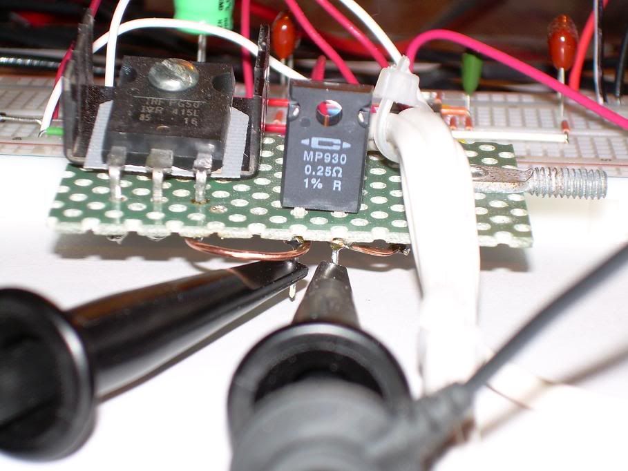
            I just received my replacement 0.25 ohm "shunt" resistor Caddock High Performance Film Resistors it's a "non-inductive" 30 watt type MP930-0.25-1% , I am in the process of removing the wire wound type "Dale" RS-2B .25 ohm 3 watt 3 % that was use on all testing numbers 1 through 8 .

            Designing With Caddock MP Series
            TO-Style Heat Sink Mountable Power Film Resistors


            As soon as it's installed I will start testing later today to publish the Images and Data Sheets for comparison purposes between the two shunt resistors that has been used in my extensive circuit testing and evaluation.

            Glen
            Open Source Experimentalist
            Open Source Research and Development

            Comment


            • TEST #9 - New Shunt & Re-test of TEST #8

              Hi Everyone,

              Here is Test #9 with the new shunt a 0.25 Ohm resistor from "Caddock" High Performance Film Resistor, "non-inductive" 30 Watt, type MP930-0.25-1%, this is a re-test of TEST #8

              *The TDS 3054C oscilloscope probes are a type Tektronix P6139A with the standard 6" grounding leads.


              ************************************************** *******

              Channel 1 - Mosfet source shunt
              Channel 2 - Mosfet drain
              Channel 3 - 555 Timer pin #3
              Channel 4 - 24 VDC "Liquid" Lead Acid Battery Bank


              Channel-3_555_SNAPSHOT

              ( 555 Image Readings Taken Prior to 24 Volt Battery Connection )


              40us_11-13-09

              40us_11-13-09.png Image
              40us_11-13-09.CSV Spread Sheet File


              20us_11-13-09

              20us_11-13-09.png Image
              20us_11-13-09.CSV Spread Sheet File


              2us_11-13-09

              2us_11-13-09.png Image
              2us_11-13-09.CSV Spread Sheet File


              1us_11-13-09

              1us_11-13-09.png Image
              1us_11-13-09.CSV Spread Sheet File


              100ns_11-13-09

              100ns_11-13-09.png Image
              100ns_11-13-09.CSV Spread Sheet File

              ************************************************** *******
              This is a test using only two oscilloscope probes with one probe tip on Channel-1 between the Mosfet and Shunt and Channel-2 between the Shunt and the Battery Negative (B-) terminal.

              Both probe grounds Channel-1 and Channel-2 connected to a separate isolated AC ground point "NOT" to the battery negative (B-) terminal


              Channel 1 - Mosfet Source to Shunt
              Channel 2 - Shunt to Battery Negative
              Channel 3 - 555 Timer Pin #3
              (no probe connection - reference only)


              MOSFET_SHUNT_BAT_N_555_11-13-09

              MOSFET_SHUNT_BAT_N_555_11-13-09.png Image
              MOSFET_SHUNT_BAT-N_555_11-13-09.CSV Spread Sheet File

              All Images and data by a Tektronix TDS 3054C from the Tektronix Corporation

              Glen
              Last edited by FuzzyTomCat; 11-14-2009, 07:24 PM. Reason: added 555 timer snapshot info - 100ns mismark - added scope probe info
              Open Source Experimentalist
              Open Source Research and Development

              Comment


              • Very nice to see this Fuzzy. Nice harmonics. Looks really promising.

                Well done and thank you - yet again - for all this hard work. What star.

                Comment


                • Glen, I'm dumbfounded - I really thought that inductive resistor would have had a more dramatic effect on the CSR trace. That's the last time I go against my intuition and listen to Poynt. Sorry for putting you through all this.

                  So, we still have to find an answer to why that negative transition occurs in that point in time.

                  And, thank you for triple verifying that we have absolutely no ground loop problems. That drain pulse has got to be one of the cleanest inductive collapse waveforms I have ever seen in my life.

                  I'll see what I can do to get all the math surrounding the lead inductance figured out.

                  GREAT JOB!

                  Last edited by Harvey; 11-14-2009, 09:57 AM.
                  "Amy Pond, there is something you need to understand, and someday your life may depend on it: I am definitely a madman with a box." ~The Doctor

                  Comment


                  • Harvey and Glen and anyone who may be interested. I've been guilty of never really studying waveforms on our own tests. Nor did I make accurate record because, frankly, I did not see the need for this. Retrospectively I see that this was a gross oversight.

                    Nor can I explain the polarity difference of the voltage across the Load Resistor and the source shunt - which seems to be intriguingly anomalous. However, I have now gone through my early dissertations on an interpretation of a the model as it relates to current flow. What I repeatedly referenced was a 'shadow' cycle - the point being that this is only allowed at the point at which current flow from a source is interrupted. In my mind's eye I saw this as a flow of current enabled in the opposite direction of the input flow. Subject to the availability of a closed circuit - this would then move in an opposite direction to the original applied potential difference. Hence the requirements of the MOSFET's body diode.

                    The point is this. It is possible that the collapsing fields in the inductor induce this second shadow cycle - and that this eludes detection on our intruments precisely because it moves through the centre of load resistor and either through the air or through the centre of the connecting wire to impress the negative cycle on the far side of the supply source - in our case, being the batteries. That way the current itself may then be hidden from detection with the probes on the exterior of the components as is required by conventional measurement.

                    This means, effectively that the energy on the load resistor may be delivered to the battery, as seems evident from the voltage readings across the batteries, and then through the batteries - as seems evident from the voltage polarity across the source shunt. But how the two currents manage the same path? That needs to be explained. Any suggestions would be of some considerable interest here.

                    Also apparent, and as we've referenced and, indeed, will need to be stressed in the paper, is the fact that the waveform is not easily accessed. It seems, somehow that it needs to be teased out of the circuit and that it relates to the circuit finding it's own 'self regulated' oscillation or resonance condition. This, in a strange way, is a both a comfort and a concern. It's a finely tuned moment and requires some skill at tuning it in. But - given the right learning here, then that moment can be found. Again. What a tribute to Fuzzy that he has done this - I'm sure, and this fact, greatly enabled by his fortunate replication of the required inductance. And that, in turn, may be related to the width of the resistor. But I'm entirely satisfied that the trick here is to let the components find that moment. It is not easily imposed - based as it is on the subtle variations in each circuit board. What does seem to follow, as day follows night, is that the benefits are always evident subject to the evidence of that haromonic. And more to the point. No wonder this has eluded dectection for so long. How many experimentalists have ever deliberately enabled this self-resonating frequency? And why should they have troubled themselves to look for it?
                    Last edited by witsend; 11-16-2009, 02:10 AM. Reason: repetition

                    Comment


                    • So - to continue with the question - I'm now proposing this. The potential difference transferred from the drain spike is returned to the material of the battery - where the energy/current/zipons originated. It adds to the potential difference of the battery. Surplus energy/current/zipons that emanated from the load resistor are passed through the battery onto the source shunt and returned to its source - again being that load resistor.

                      In effect positive current flow does not have a closed circuit path and is therefore blocked. Negative current flow does have a closed circuit and is therefore not blocked. And the only explanation I can find for the lack of evidence of that simultaneous negative flow between the load resistor and the drain - is that it is somehow 'hidden' in the material through which it passes - or through the air. We know that both Aaron and Fuzzy had gross RF evidence. Both had lights turning off and on and Fuzzy even had intereference on his TV.

                      Perhaps this hidden event is really in line with that proposed 'shadow cycle'?
                      Last edited by witsend; 11-16-2009, 02:41 AM. Reason: spelling and clarification

                      Comment


                      • Keep em coming guys thanks for all the new info, progress is addictive?

                        Okay still ironing out bugs, just adding this here to let you know we are still in the shop . Thanks for being patient and helpful for all's PDF guys, i sincerley appreciate it.

                        Ash

                        Hey Glen / all,

                        I have followed Glen's advice on removing the back spike recovery diode / capacitor / discharge resistor, and tuning the gate resistance for the maximum voltage on the 24v battery. The board used was set for 2.4KHz 3.7%. Nothing exciting to write back about, but here is a log of the test:

                        * battery no load: 25.65v
                        * 38mA load, run for 1 minute with ferrite rods: 25.5v
                        * 28mA load, run for 5 minutes with ferrite rods: 25.45v
                        * Experimented with adjusting 10 ohm variable resistor - no improved results. * Calibated back to 5.5 ohms.
                        * Re start timer.
                        * 28mA load, with ferrite rods: 25.5v
                        * 28mA load, run for 1 minute with ferrite rods: 25.46v
                        * 28mA load, run for 3 minutes with ferrite rods: 25.45
                        * checked a few times between the 3 minute mark up until 40 minutes run - the battery stabilized at 25.45v
                        * I removed the ferrite rods from inside the resistor, the current draw went up, the battery voltage went down. I quickly re inserted the ferrite rods and the battery voltage stabilized at 25.45v
                        * There was no noticeable heat on the inductive resistor

                        Looking at the Quantum October 2002 article, I see they have a 100 ohm variable resistor on the mosfet gate, and that they get frequency oscillations between 143KHz and 200KHz @ 1.3% on a 2.4KHz 3.7% 555 timer board.
                        These oscillations must be the same wild oscillations I experienced previously. The quantum article states that the 10 ohm wirewound resistor also got fairly warm using 2.4KHz, 3.7%, and the high frequency mosfet oscillations.

                        What do you suggest?

                        Andrew

                        Comment


                        • Hi Ash and Andrew,

                          You guys are working so hard and somehow not getting that optimised number? I think I need to leave this to Fuzzy to try and explain. But if you read my previous posts - you'll see that the trick is to allow the apparatus to find its own preferred oscillation. If it gets chaotic - that's a really good thing. It's usually when the resonance is trying to stabilise and can't.

                          sorry to read of the struggles. Hopefully Fuzzy can give some advise here.

                          Comment


                          • Test #10

                            Hi everyone,

                            Here is TEST #10 .... it's a one (1) hour test with 40us and 2us readings taken every six (6) minutes for a total of eleven (11) readings or twenty two (22) Image and Data files for one (1) hour.


                            Rosemary Ainslie COP>17 Heater Circuit
                            "Quantum" October 2002

                            Replication Components -

                            1) International Rectifier - IRFPG50 HEXFET® Power MOSFET
                            w/ Sil-Pad insulator between Mosfet and Heat Sink

                            2) Fairchild Semiconductor - NE555N Timer

                            3) Vishay Spectrol - SP534 Percision Potentiometer/ 10-turn 2-Watt

                            4) Exide Technologies Battery "Liquid Lead Acid" Model # GT-H - TRACTOR 12V 12Ah CCA 235

                            5) CSB Battery Company "Gel Lead Acid" #GP 1270 F2 / 12 Volt 7.0 Ah

                            6) Prototype "Quantum" Load Resister 10 ohm + - 1%

                            7) "Shunt" - Caddock High Performance Film Resistor "non-inductive" 30 watt type MP930-0.25-1%

                            Temperature Measurements -

                            Fluke 62 "mini" IR Themometer ( used maximum reading on each componenet )

                            Digital Mulit Meter -

                            Fluke 87 DMM true RMS

                            ************************************************** *******

                            Channel 1 - Mosfet source shunt
                            Channel 2 - Mosfet drain
                            Channel 3 - 555 Timer pin #3
                            Channel 4 - 24 VDC "Liquid" Lead Acid Battery Bank


                            TEST #10 Complete Original Image & Data .Zip File Set w/ Key

                            SNAP SHOT CHANNEL-1 40us

                            Snap_Shot_40us_11-15-09.png Image File

                            1_40us

                            1_40us_11-15-09.png Image File
                            1_40us_11-15-09.CSV Spread Sheet File
                            1_2us
                            1_2us_11-15-09.png Image File
                            1_2us_11-15-09.CSV Spread Sheet File


                            2_40us

                            2_40us_11-15-09.png Image File
                            2_40us_11-15-09.CSV Spread Sheet File
                            2_2us
                            2_2us_11-15-09.png Image File
                            2_2us_11-15-09.CSV Spread Sheet File


                            3_40us

                            3_40us_11-15-09.png Image File
                            3_40us_11-15-09.CSV Spread Sheet File
                            3_2us
                            3_2us_11-15-09.png Image File
                            3_2us_11-15-09.CSV Spread Sheet File


                            4_40us

                            4_40us_11-15-09.png Image File
                            4_40us_11-15-09.CSV Spread Sheet File
                            4_2us
                            4_2us_11-15-09.png Image File
                            4_2us_11-15-09.CSV Spread Sheet File


                            5_40us

                            5_40us_11-15-09.png Image File
                            5_40us_11-15-09.CSV Spread Sheet File
                            5_2us
                            5_2us_11-15-09.png Image File
                            5_2us_11-15-09.CSV Spread Sheet File


                            6_20us

                            6_20us_11-15-09.png Image File
                            6_20us_11-15-09.CSV Spread Sheet File
                            6_2us
                            6_2us_11-15-09.png Image File
                            6_2us_11-15-09.CSV Spread Sheet File


                            7_40us

                            7_40us_11_15_09.png Image File
                            7_40us_11_15_09.CSV Spread Sheet File
                            7_2us
                            7_2us_11_15_09.png Image File
                            7_2us_11_15_09.CSV Spread Sheet File


                            8_40us

                            8_40us_11-15-09.png Image File
                            8_40us_11-15-09.CSV Spread Sheet File
                            8_2us
                            8_2us_11-15-09.png Image File
                            8_2us_11-15-09.CSV Spread Sheet File


                            9_40us

                            9_40us_11-15-09.png Image File
                            9_40us_11-15-09.CSV Spread Sheet File
                            9_2us
                            9_2us_11-15-09.png Image File
                            9_2us_11-15-09.CSV Spread Sheet File


                            10_40us

                            10_40us_11-15-09.png Image File
                            10_40us_11-15-09.CSV Spread Sheet File
                            10_2us
                            10_2us_11-15-09.png Image File
                            10_2us_11-15-09.CSV Spread Sheet File


                            11_40us

                            11_40us_11-15-09.png Image File
                            11_40us_11-15-09.CSV Spread Sheet File
                            11_2us
                            11_2us_11-15-09.png Image File
                            11_2us_11-15-09.CSV Spread Sheet File


                            ************************************************** *******

                            TEMPERATURE - IMAGE & DATA "KEY"


                            ************************************************** *******

                            100ns


                            All Images and data by a Tektronix TDS 3054C from the Tektronix Corporation

                            Glen
                            Last edited by FuzzyTomCat; 11-17-2009, 07:28 PM. Reason: added Test #10 Zip file
                            Open Source Experimentalist
                            Open Source Research and Development

                            Comment


                            • Thanx Glen,

                              A much needed test to locate the deviation of the Ch1 mean. And the harmonic sweep is very obvious in these as well.

                              I have the corrections of the test configurations documented for tests 1-7 and for 8 and beyond. Hopefully I can get that posted up sometime this week after I finish on the inductive reactance analysis and get it presentable. I also intend to implement a cross check against your estimated resistor inductance and test data to compare to measured instantaneous current. You may recall also that I mentioned the ring form on the Ch1 data regarding the slope decay of each successive wave - I knew I had seen it before; Hewlett Packard published a chart of Laplace Transforms and that matches number 4 in their chart for the time function: f(t) =0,t<0,e^-αt(sin βt, t>0. So it is a familiar progression decay of standard ringing with no special characteristics and easily duplicated mathematically. The timing of the negative I still have not figured out and that little spike off in the middle of nowhere with no explainable cause also has me puzzled as well. There must be an event occurring that we are not monitoring...a high to low transition through a capacitor to ground somewhere, I just haven't checked it out well yet.

                              I don't anticipate any issues with any of the inductive wiring although the 80MHz on that 6" piece between the CSR and the grounding star would normally raise my eyebrows a bit. The fact is, those signals have such a low amplitude, and they are ringing above and below the mean value such that they entirely cancel so the real frequency is well down in the kHz where it just becomes moot. What is even more intriguing is the timing of that impulse. If we use the slope of the load resistor collapse as our determining frequency component for the inductive reactance calculations and apply that to the CSR leads, then we are admitting that negative current is flowing through a closed MOSFET the wrong way when the other side of that MOSFET is at 600V against its flow - can it really be? That body diode is surely reverse biased to the max at that instant. How is that current flowing? Source to gate leakage?; I wouldn't think there is a potential there either. The Spatial test you did ruled out any 'boot strap' effect that I thought maybe happening. So I find myself entertaining some sort of capacitive push occurring in time 90° before the event even occurs. This would be the 100V bump capacitively pushing through the battery, out the B(-) and through the shunt before the body diode has a chance to open and would be likened to charging up the source pin from the back side in anticipation of the expected negative spike on the drain that never occurs. That drain spike drops just as fast as it builds and that 600 volts is being spent somewhere. Since it is not going through the MOSFET it must be moving through the load resistor back to the B(+) terminal. This produces a ringing at the B(+) which can be seen in the scope shots. So all of that energy is either spent in the resistor or put back into the battery. The puzzling thing is that it seems to be just fine without a closed circuit and our CSR just isn't monitoring the current flow from the drain to the B(+) with the MOSFET closed and the drain always above zero so as to prevent the body diode from conducting.

                              So what other possibilities are there? Quantum Tunneling, Negative Resistance, Electromagnetic return path, Bidirectional Vortex currents, what else?

                              Even if we were upside down on our current by 2W we still would have to account for 200% more heat than it should be doing.

                              "Amy Pond, there is something you need to understand, and someday your life may depend on it: I am definitely a madman with a box." ~The Doctor

                              Comment


                              • Originally posted by ashtweth View Post
                                Keep em coming guys thanks for all the new info, progress is addictive?

                                Okay still ironing out bugs, just adding this here to let you know we are still in the shop . Thanks for being patient and helpful for all's PDF guys, i sincerley appreciate it.

                                Ash

                                Hey Glen / all,

                                I have followed Glen's advice on removing the back spike recovery diode / capacitor / discharge resistor, and tuning the gate resistance for the maximum voltage on the 24v battery. The board used was set for 2.4KHz 3.7%. Nothing exciting to write back about, but here is a log of the test:

                                * battery no load: 25.65v
                                * 38mA load, run for 1 minute with ferrite rods: 25.5v
                                * 28mA load, run for 5 minutes with ferrite rods: 25.45v
                                * Experimented with adjusting 10 ohm variable resistor - no improved results. * Calibated back to 5.5 ohms.
                                * Re start timer.
                                * 28mA load, with ferrite rods: 25.5v
                                * 28mA load, run for 1 minute with ferrite rods: 25.46v
                                * 28mA load, run for 3 minutes with ferrite rods: 25.45
                                * checked a few times between the 3 minute mark up until 40 minutes run - the battery stabilized at 25.45v
                                * I removed the ferrite rods from inside the resistor, the current draw went up, the battery voltage went down. I quickly re inserted the ferrite rods and the battery voltage stabilized at 25.45v
                                * There was no noticeable heat on the inductive resistor

                                Looking at the Quantum October 2002 article, I see they have a 100 ohm variable resistor on the mosfet gate, and that they get frequency oscillations between 143KHz and 200KHz @ 1.3% on a 2.4KHz 3.7% 555 timer board.
                                These oscillations must be the same wild oscillations I experienced previously. The quantum article states that the 10 ohm wirewound resistor also got fairly warm using 2.4KHz, 3.7%, and the high frequency mosfet oscillations.

                                What do you suggest?

                                Andrew
                                Hi Ash and Andrew,

                                Thanks again for your testing and evaluation of the RA COP>17 Heater Circuit .....

                                I am curious about the results you are having possibly could be because of the prototype "Quamtum" load resistor you have constructed ..... I was able to find your Images you posted earlier in the thread POST #2989

                                Imageshack - glensresistorreplicatioy
                                Imageshack - glensresistorreplicatio

                                I think there may be a heat sink problem with the resistor core material and the silicone covering that was used .... can you list the materials that was used for construction so Harvey, Rosie or I can make a determination of what could be possibly wrong so we can resolve it. I suggest you may try the purchased load resistor you have and see if there is any heat generated with it to make sure all your circuit components are working properly.

                                Do you know if you will be able to get any oscilloscope wave form shots .... I know at present you haven't a scope .... but were all hoping

                                Best Regards,
                                Glen


                                ************************************************** *******
                                EDIT - I just noticed you posted a "Ferrite" resistor core .......

                                Ferrite is a class of ceramic material with useful electromagnetic properties and an interesting history. Ferrite is rigid and brittle. Like other ceramics, ferrite can chip and break if handled roughly. Luckily it is not as fragile as porcelain and often such chips and cracks will be merely cosmetic. Ferrite varies from silver gray to black in color. The electromagnetic properties of ferrite materials can be affected by operating conditions such as temperature, pressure, field strength, frequency and time.

                                There are basically two varieties of ferrite: soft and hard. This is not a tactile quality but rather a magnetic characteristic. 'Soft ferrite' does not retain significant magnetization whereas 'hard ferrite' magnetization is considered permanent. Fair-Rite ferrite materials are of the 'soft' variety.

                                Ferrite has a cubic crystalline structure with the chemical formula MO.Fe2O3 where Fe2O3 is iron oxide and MO refers to a combination of two or more divalent metal (i.e: zinc, nickel, manganese and copper) oxides. The addition of such metal oxides in various amounts allows the creation of many different materials whose properties can be tailored for a variety of uses.


                                Could you verify that this is what your prototype "Quantum" load resistor core is made of ..... this could be a problem if it is "Ferrite"........
                                Last edited by FuzzyTomCat; 11-16-2009, 11:02 PM. Reason: added edit
                                Open Source Experimentalist
                                Open Source Research and Development

                                Comment

                                Working...
                                X