Hi everyone,
Their is many replicators out there that are asking how can I do this with my older oscilloscope that is 10mhz to 150mhz ...... well its not easy but you can definitely get in the ball park for sure.

The resistance on the gate pot needs to be between 7 and 3 ohms using a DMM across the pot terminals .... 5 to 6 ohms for best results
The battery voltage across the 24 volt battery bank can be monitored with another DMM and tuned to the highest voltage using the gate pot for fine adjustments between the 7 and 3 ohm area.
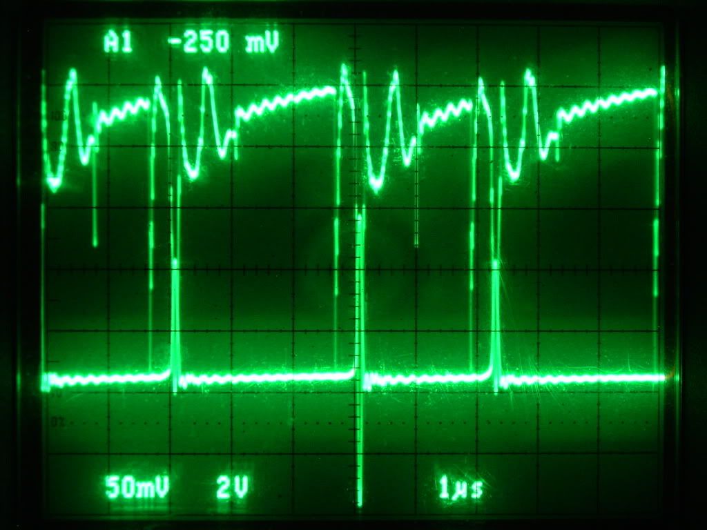
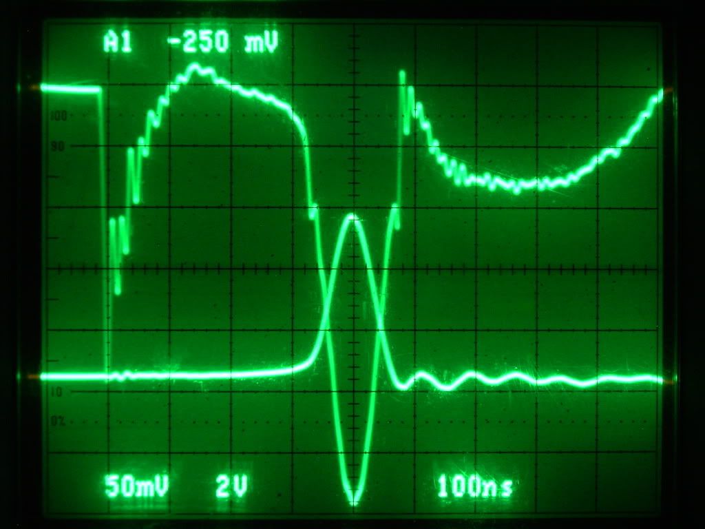
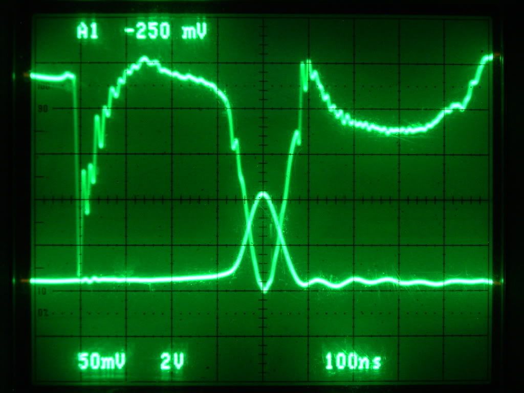
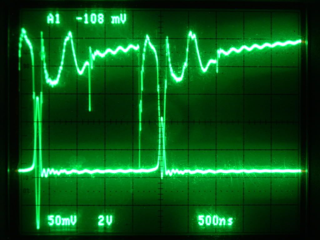
The Channel 1 is used at the Mosfet shunt area between the 0.25 ohm resistor and the Mosfet "source" pin, "SCOPE" - set at 50mv and probe at X10
The Channel 2 is used at the 24 Volt battery bank positive and negative but connected within 18 inches from your "load resistor", "SCOPE" - set at 2v and probe at X10
The "load resistor" will be from 110 degrees F to 150 degrees F
The "Mosfet" will be from 140 degrees F to 160 degrees F
( temperatures measured with a IR non contact thermometer )
If using these setting this is what should be seen .....
A example of a earlier run using the Tektronix TDS 3054C
Channel 1 - Mosfet "source" shunt
Channel 2 - Mosfet "drain" *
Channel 3 - 555 timer / pin #3
Channel 4 - 24 Volt Battery Bank
As you can see the Mosfet Drain @ 520 Volts rises at the same time the 24 Volt battery bank rises to 70 Volts

I hope this helps all the replicators out there so you know this can be done and get some impressive results yourself

Glen


 , i just try to pitch in my part and consider my self equal like ever one working together, its addictive being a community
  We are almost onto winding Glen's inductor for some more tests. Sorry we have not been able to contribute much technical but rest assured when we get the Inductor done can do a whole bunch of tests for all.


Leave a comment: