 Larger Pic
 Larger Pic
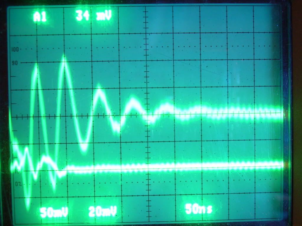
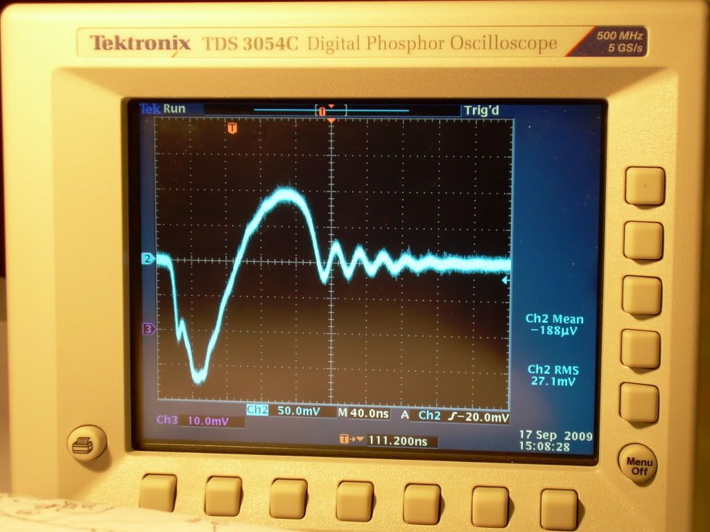
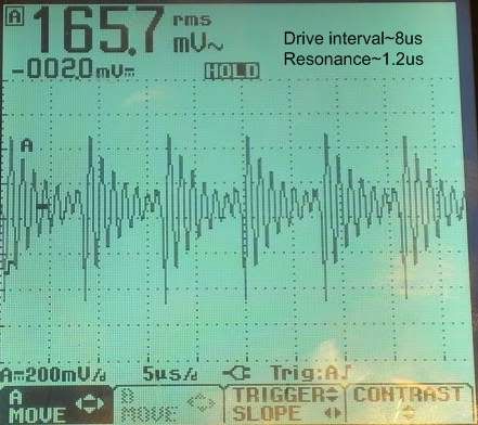
It was determined that there is an unknown component in the Radio-Location Bands above 3GHz present in the 'noise' and sufficient to intrude on the data. This signal was present even with the power stage inoperable. The source of this signal is yet to be determined. It may be finding its way into the circuit from the scope ground system.
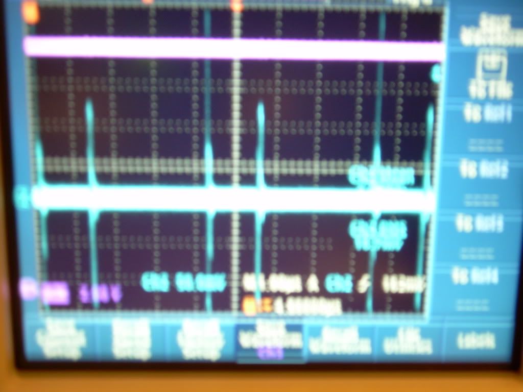
The test configuration used is presented above and organized in such a way so as to reveal any breakdown in KCL. The operation was Aperiodic. The resistor used was Glen's, documented elsewhere. I was not concerned with the circuit timing or the components used for the timer, as this test was aimed at the aperiodic operation and its effects on the current flow in the circuit. The CSR (current sensing resistors) are all 0.25 Ohm 5%. Therefore I charted a minimum and a maximum value for the current in each leg of the circuit.
The instantaneous voltage at CH1 was used for power calculations for each leg based on the Max current (min tolerance resistance value). The absolute value of that current was used. Thus all of the power values are above zero for all three legs.
The sum of the timer leg and load leg were compared to the B(+) leg and the 'missing' value was charted. The 'missing' instantaneous current ranged from +285mA to -305mA and may be directly related to the unknown signal. However, there is a clear indication of positive current flow through the B(+) leg at that point in time that a negative current flow exists in the load leg. The value of this event appears to be greater than the maximum recorded amplitude of the noise present, but we must realize the the scope used and the samples taken may be inadequate for GHz signals - although it did register that frequency according to Aaron.
Because of the very aperiodic data, I did calculate the average power for each leg to get a better overall picture using the technique mentioned above. The average timer power was 316mW. The average power for the load was 410mW. The average power for the B(+) leg was 3.5W. The instantaneous power is charted above. Note that the timer and load show the bursts while the B(+) is constant.
I did try to look for inductive delays and shifted current, but the data makes this almost impossible.
I would like to revisit this test when the unknown energy component is discovered and dealt with. We cannot overlook the possibility that it may be coming from the battery or 'noisy' sensing resistors, or an interaction between the two.
At first glance, it appears that this circuit is taking power from the B(+) leg and returning it to the B(-) leg by some other path. This path can be RF, thermal or some other form of energy exchange otherwise undocumented as of yet. Or it could be and exchange with another energy pool. It definitely warrants deeper analysis and study.


 ..... but the Mosfet seems not to get over 140 degrees F ever that I've seen with a heat sink like I have.
Leave a comment: