Announcement

Collapse
No announcement yet.

COP 17 Heater | Rosemary Ainslie

Collapse
This topic is closed.
X
This is a sticky topic.
X
X
 
  • Filter
  • Time
  • Show
Clear All
new posts

  • Harvey
    replied
    Glen,

    Have a look at this diagram:

    Aarons Revised Circuit

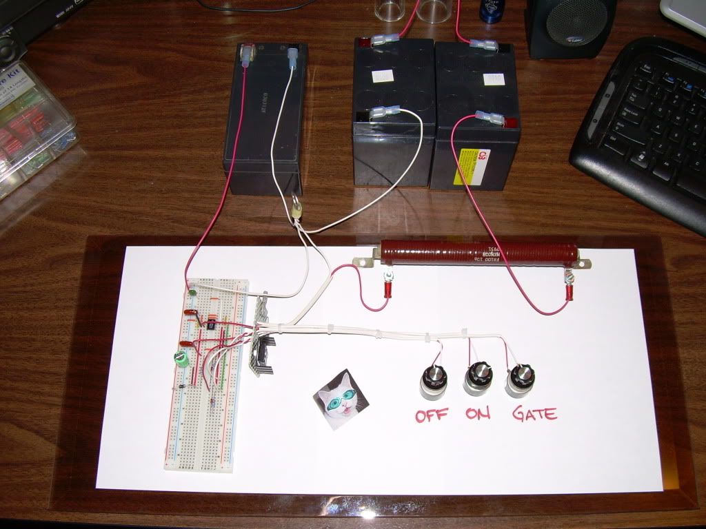
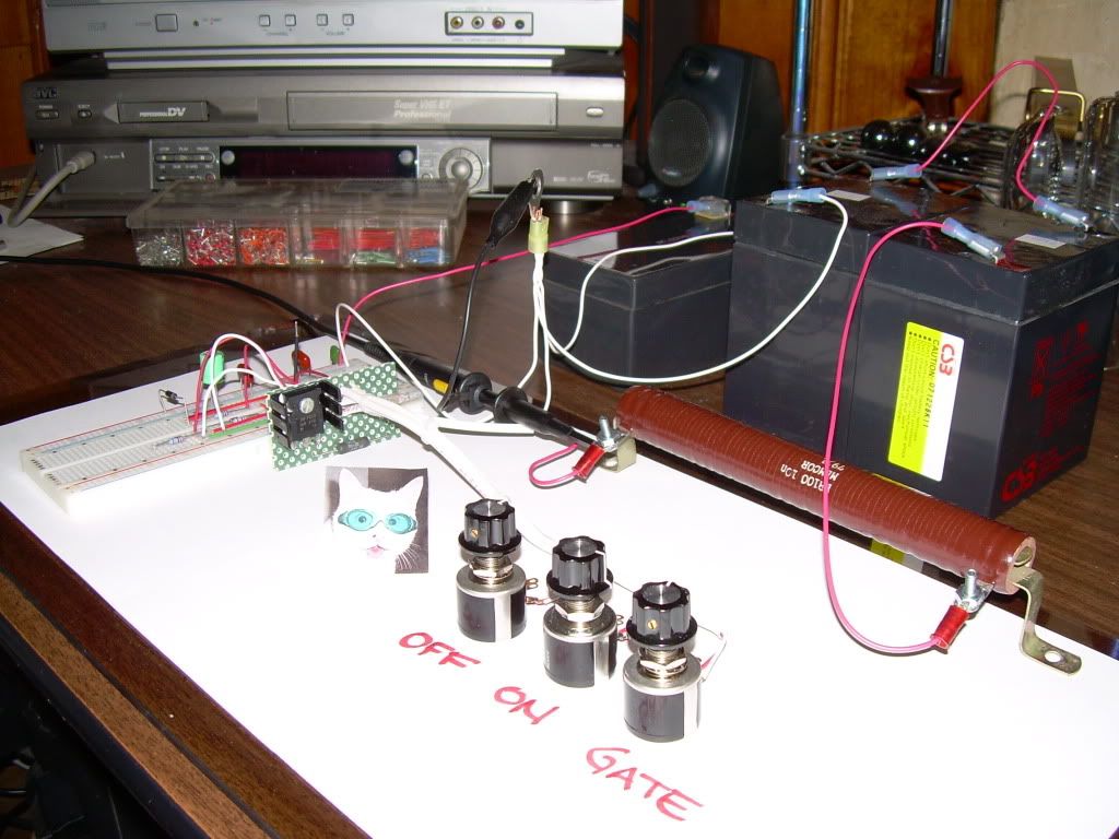
    Note that the 0.25 Ohm sensing resistor is between pin 1 of the
    555 and B(-)

    Note that the 1 Ohm sensing resistor is between the IRFPG50 and B(-)

    So the probes all reference to B(-).
    One probe to Pin 1 of 555, one to Source on IRFPG50, and a third to B(+)

    Cheers,

    Leave a comment:


  • FuzzyTomCat
    replied
    Originally posted by Aaron View Post

    I used 3 channels on this one.

    Channel 1, 2, and 3 all have a shared ground.
    Channel 1, probe to other side of 0.25 ohm shunt on the 555 circuit.
    Channel 2, probe to mosfet side of 1 ohm shunt for load measurements.
    Channel 3, probe to positive of battery.
    Hi Aaron,
    For clearification purposes ...... on the RA Heater Circuit (revised: August 12, 2009)

    Channel 1, probe to other side of 0.25 ohm shunt on the 555 circuit.
    Is the probe between the .25 ohm resistor and the Battery (-) or between .25 resistor and the IRFPG50 Mosfet?

    Channel 2, probe to mosfet side of 1 ohm shunt for load measurements.
    Is there a 1 ohm resistor in the circuit diagram or is this a additional resistor required "just" for measurement and testing, and how is it connected to the circuit?

    Channel 3, probe to positive of battery.
    I assume this is the 24 volt battery bank and not the 12 volt seperate battery for the 555 circuit.

    I think these answers may help me and other experimenters not totally familiar with what scope connections that were used for the common end results needed or to be found.

    Thanks again for your efforts, help and support on this project, I'm afraid with the first harsh negative responses from the few we saw this would have had a much different result.

    Best

    Leave a comment:


  • Aaron
    replied
    multiple samples

    Harvey, this is on the multiple samples:

    Raw and untouched data:
    http://www.feelthevibe.com/free_ener...i-dipa2raw.csv

    Crunched - but nothing shaved from data before first waveform or after last waveform to make perfect whole number waveforms. You can do that if you want. But at this many samples, it should be very accurate. Would love to see your spreadsheet chart pics of this one to see how it matches the pics below. That is a great confirmation that the data is from the waveforms that it is claimed to be.
    http://www.feelthevibe.com/free_ener...a2crunched.csv

    About an hour later I took pics before I forgot to do so on the spot.

    Here are 2 pics...first is how the sample was taken. Second is zoom in to see waveform. Third is what the fluke is showing across the load. I have gate resistance at max 5k...just experimenting but still getting cooling effect and net negative wattages. You can see the lower half is like the top half.

    Anyway, this should show that the waveform I selected didn't happen to be an anomaly. At this sample range, there is still a negative average wattage.


    Leave a comment:


  • FuzzyTomCat
    replied
    Originally posted by Aaron View Post
    Hi Glen,

    I don't know how important it is to have the same 555 as I have... NE555N. I bought them at radio shack. I learned from Peter that there are low power versions. I didn't know the existed.

    I may be using more power than I need and might get better gains with a lower power 555. OR, there might be something to using the higher power one that enhances what is going on. I could try a lower power one and see what happens.
    Hi Aaron,
    I still have another Fairchild NE555 this other NTE955M came from Fry's Electronics Fry's Home Electronics | Computer Parts & Accessories, Software, Games, TVs, Cameras - Frys.com in Wilsonville just down the street from Tektronix only about 20 minutes away from me, and they have a good supply of electronic parts. The one NE555 that blew, popped as soon as it got power, kinda strange but I have extras

    I did see some really different wave forms before I got the ringing scope shots, can't wait to see what this puppy can do

    Best

    Leave a comment:


  • Aaron
    replied
    Ne555n

    Originally posted by FuzzyTomCat View Post
    The first time I turned it on the smoke leaked out of a Fairchild NE555 so my plan B was a NTE955M http://www.nteinc.com/specs/900to999/pdf/nte955.pdf
    Hi Glen,

    I don't know how important it is to have the same 555 as I have... NE555N. I bought them at radio shack. I learned from Peter that there are low power versions. I didn't know the existed.

    I may be using more power than I need and might get better gains with a lower power 555. OR, there might be something to using the higher power one that enhances what is going on. I could try a lower power one and see what happens.

    Leave a comment:


  • Aaron
    replied
    temperature

    Originally posted by Harvey View Post
    Aaron, do you have any temp reading data that can be sync'd to the A column in a CSV? Even if it is just two or 3 readings as long as we can associate the time frame with the waveform analysis and temperature readings.
    The temp would be virtually identical for the whole sample of 1 waveform.

    The division on that scope shot of the shunt wave... is 400ns per division. the one waveform takes up 60% of the width of the whole screen so 6000 samples about. That is about 12,000ns for 1 waveform at 6000 samples.

    The thermo probes readout shows me only as detailed as 1/10 C intervals and it definitely won't fluctuate at that level for one waveform. Depending on tuning, it could be several minutes between each 1/10 of a C change.

    Leave a comment:


  • Harvey
    replied
    Originally posted by witsend View Post
    Poynt - this is rather less than I would have expected from you. The Tektronix is more than equal to the frequency measurement. And the 'below zero' heat measurement is accurate. You're arguing the experiment on the grounds of data?

    Please tell us if you can find these results in your programs. To question Aaron's knowledge of where to put the probes is insulting in the extreme and inappropriate to the general tenor of this thread.
    .99 just misread the scope, it reads 1.5 not 5 megahurts.

    Leave a comment:


  • Aaron
    replied
    Tuning the circuit

    @Everyone

    For tuning, focus on the dc value at the shunt compared to the rms at the shunt. Have both readings on screen at same time. It isn't necessary to try to get negative like I did. If heat is your goal, you need positive wattage flowing into the circuit to do that.

    That one piece of advice that originally came from Rosemary, about focusing on dc/rms comparison, will save you LOTS of time from trial and error.

    You want the biggest spread you can get so that the dc at the shunt is much, much lower than the RMS at the shunt.

    The bigger the spread, the better your efficiency and COP. The dc reading, the lower it is, the more balanced your waveform is above and below the ground level.

    At lower DC readings, you'll have less heat but will probably be much more efficiently produced than the control. If you want more heat, you may need more DC at the shunt but make sure the circuit is tuned so the RMS is way high.

    It is a waste of time to do any draw down test or otherwise if those numbers aren't far enough apart. Once you have your best settings by doing that and you could analyze the power like I did with the data dump, but then do the draw down. That saves lots of time so you won't be doing drawdowns on trial and error basis. The drawdowns take a LONG time. Good to have 2 people that can watch it around the clock.

    When tuning your dials, look at the waveform and just go through every combination you can between the 3 pots just for the learning experience. You will get the feel for how to even out the waveform above and below.

    There is a very profound implication here about the balanced waveform. Everyone is programmed to see a positive on pulse then a spike that is a very narrow width - it appears to have been widely assumed that the collapsing magnetic field

    Did anyone ever say or prove that we can't WIDEN out its time frame in the negative zone? I don't think so. The more you can widen it out, the less positive there is of the waveform and that brings it towards balance.

    Of course the amplitude reduces but the area under ground area starts to mirror the positive side. And you can then get more under than over.

    At this point, I see a limit as to how much negative it can go with this switch. There may be other switching methods that can bring it more negative - I'll leave it to the open minded EE's or engineers to come up with something for that.

    With my parts, I'm limited to this basic circuit that has been posted for years but with a few minor modifications.

    And use liquid lead acid batteries and not gel cells.

    And 10 turn tuning pots in the right ranges.

    Leave a comment:


  • FuzzyTomCat
    replied
    Hi everyone,

    I got better results without using any small gauge wire clips or any switches ( some switches add a lot of resistance) here is the set up [pots AWG 20 solid / Battery, 10 ohm resister AWG 18 solid] the RA Quantum revised: August 12, 2009 circuit was on for about 30 minutes with the shots shown and the battery went down from 24.8 to 24.6 this is as soon as I got the ringing everyone knows.


    The first time I turned it on the smoke leaked out of a Fairchild NE555 so my plan B was a NTE955M http://www.nteinc.com/specs/900to999/pdf/nte955.pdf

    Tomorrow I'll give it a whirl with the probe locations from Aaron (thanks Aaron) and record the wave forms with a some type of camera because theres only a capture feature on this scope a 1998 model ..... nice though

    @ Rosemary , I haven't made the 10 ohm resistor yet, still waiting on the proper wire and type.

    @ Harvey, Thank for the encouragement and help, I had the scope intensity up, never had to shoot a wave form before

    Best Regards,
    Glen
    Last edited by FuzzyTomCat; 08-28-2009, 09:48 AM. Reason: added AWG wire gauge

    Leave a comment:


  • witsend
    replied
    Originally posted by Harvey View Post

    However you accomplish it, it the total energy that leaves the load is more than the energy dumped into the load, the load must supply the energy either from itself or the pool of energy it contains in the form of temperature. In our case it is conventionally unlikely that the resistor is oxidizing or being consumed in some other fashion that results in a consistent holding of a temperature less than ambient. Especially if power is being dissipated in it. Therefore it is probable that it gives up it's thermal equilibrium in order to satisfy the energy exchange. This is nothing new. Einstein had few patents to his name but this is one he evidently felt strongly about: Using Heat to Refrigerate This type of cooling system is well known in the RV industry where almost all refrigeration systems work off of a heat principle and have no compressor. It is possible that your frequencies and arrangement do provide a release of extra energy from the resistor. Using RF to cool things

    Well, back to my 555 stuff

    I find this a encouraging. Had no idea of this negative voltage effect. In which case - is the 'heat' dissipated at the resistor only evident if the net value of the voltage across the resistor is above zero? And is the heat then also the difference between the two values above and below zero? And then the next question. Does the negative voltage over the resistor constitute a potential recharge to the battery? If so, to my simplistic way of thinking - it may then be possible to direct the current from two parts of a voltage waveform across an inductor, the one to a non-inductive resistor and the other to the same or an alternate battery. The theoretical implications are - at its least, usable.

    It seems that this balanced negative component is more enhanced by placing the inductor behind the switch. And whichever way one looks at this - the results speak to conservation of charge which is more complete than the published circuit. Again. As I see it.

    Leave a comment:


  • Aaron
    replied
    @Glen

    Great to see the scope shots Glen!

    Rosemary is a serious master at waveform analysis!

    I used 3 channels on this one.

    Channel 1, 2, and 3 all have a shared ground.
    Channel 1, probe to other side of 0.25 ohm shunt on the 555 circuit.
    Channel 2, probe to mosfet side of 1 ohm shunt for load measurements.
    Channel 3, probe to positive of battery.

    If this is the wrong way to do it, let me know.

    I hope you'll see the same thing I did. I believe the frequency I'm using is too high and the battery won't benefit as much. If I get a lower frequency, I believe the battery will be able to charge up better and even more so, possibly, at 24 volts instead of 12.

    Can your scope log data and if so, how many samples per screen?

    Looking forward to learning more about your setup!

    Leave a comment:


  • witsend
    replied
    Originally posted by poynt99 View Post
    Your 555 timer is running at about 431kHz.

    The 5MHz showing on the 0.25 Ohm timer shunt is just noise. It's doubtful there is any real 5MHz component anywhere in the circuit wave forms.

    The "below zero" analysis is not necessarily correct. The load wave form is with the probes across the load as you stated, not with any reference to ground. Measurements need to be made to the same reference as the battery to know direction of the current.

    .99
    Poynt - this is rather less than I would have expected from you. The Tektronix is more than equal to the frequency measurement. And the 'below zero' heat measurement is accurate. You're arguing the experiment on the grounds of data?

    Please tell us if you can find these results in your programs. To question Aaron's knowledge of where to put the probes is insulting in the extreme and inappropriate to the general tenor of this thread.

    Leave a comment:


  • witsend
    replied
    Fuzzy - you're holding out on us. Did you build your resistor? I would remind you that Aaron needs one.

    So nice to see all this data coming in. Am holding my breath here for results.

    BTW If anyone ever wants to hold onto their sanity - don't ever post contentious claims. It's a recipe for accelerated aging. I know this. Early onset of arthritis, fading eyesight, extraordinary sleep patterns, random dementia and emotional control oscillating out of reach. All evidence points to degrading superstructure avalanching to an early grave. Three months ago I still felt young. Have to think hard to remember that time.

    Leave a comment:


  • Harvey
    replied
    Hi Glen,

    Now I see why the cat wears eye shields Now that is some 'intense' tracing.

    Nice ringing, but this is not the aperiodic oscillation that Aaron has demonstrated.

    Looking at the timing there, you can reduce your on-time to about 2 or 3 microseconds and even shorten your off time to as little as 8 microseconds and that would give a pretty optimal timing for conventional power dissipation in the load. That would push the duty cycle up to 25% or 30+% but it would still resonate the same.

    I can't advise yet on the aperiodic oscillation as I haven't powered mine up yet interruptions...but I can work on it now for a bit. From Aaron's posts it seems to be a matter of getting the gate resistance to a level that allows it to occur. In your case, I would increase the off time to about 400 microseconds before experimenting with the aperiodic stuff. You need to let things recuperate a bit in between hitting the resistor with more straight juice.

    Great to see it working
    Last edited by Harvey; 08-28-2009, 07:19 AM. Reason: not sure where I put my wears but it needed changed :rofl:

    Leave a comment:


  • Harvey
    replied
    Aaron, do you have any temp reading data that can be sync'd to the A column in a CSV? Even if it is just two or 3 readings as long as we can associate the time frame with the waveform analysis and temperature readings.

    .99 probably got a little confused regarding the use of the word ambient. Thermodynamic laws dictate that everything must absorb or radiate energy in order to match ambient. The only way the resistors would be lower than ambient is if there has been a change either in the ambient or in the previously thermally neutral (ambient matched) temperatures. Wind chill for instance, can reduce the temperature of an object below ambient. Thermal hysteresis and state change can also cause temperature differentials between ambient and a object immersed in the ambient. But in this case, the loads and shunts should all have started at ambient.

    As regards the noted cooling, there are a couple of things that can lead to this. RF is the most likely culprit for both the negative power results and the cooling. If you note my KCL comment, I qualified it by stating the 'wired' path. There is still a wireless path for the energy to flow and this is a difficult concept for some to grasp. Wireless power transmission is conventionally thought of as an exchange of voltage for transmitted power. In other words, at the end of the circuit, the current is the same but the voltage is spent to zero. But this does not have to be the case. We can conserve the voltage and spend the current instead. Very unconventional, but the result is some screwed up power readings when we base them on current in one leg of the circuit and it totally pisses all over KCL. But every well trained engineer knows that he can black box a transformer and end up with a current to voltage converter. This is one of the reasons a professor at MIT adamantly stressed the importance of using Faraday's laws instead of Kirchhoff's laws where dynamic fields are concerned. Kirchhoff's law is a subset of Faraday's law, which always works because it allows for path dependent analysis. When the system has an open door, as is the case with certain current consuming devices like RF power output, the path becomes important to the overall calculations. Those that grasp this concept will go far with future technology. Those that readily dismiss it will miss out on opportunities to explore seldom applied variations to the conventional application of electrodynamics.

    However you accomplish it, it the total energy that leaves the load is more than the energy dumped into the load, the load must supply the energy either from itself or the pool of energy it contains in the form of temperature. In our case it is conventionally unlikely that the resistor is oxidizing or being consumed in some other fashion that results in a consistent holding of a temperature less than ambient. Especially if power is being dissipated in it. Therefore it is probable that it gives up it's thermal equilibrium in order to satisfy the energy exchange. This is nothing new. Einstein had few patents to his name but this is one he evidently felt strongly about: Using Heat to Refrigerate This type of cooling system is well known in the RV industry where almost all refrigeration systems work off of a heat principle and have no compressor. It is possible that your frequencies and arrangement do provide a release of extra energy from the resistor. Using RF to cool things

    Well, back to my 555 stuff

    Leave a comment:

Working...
X