If this is your first visit, be sure to
check out the FAQ by clicking the
link above. You may have to register
before you can post: click the register link above to proceed. To start viewing messages,
select the forum that you want to visit from the selection below.
Jeez Fuzzy I'm not sure if that qualifies as an experimental set up. Where's all the alligator wires? Can you at least throw in a pile of spaghetti wiring and a bunch of old burnt up parts or something.
Golly Fuzzy - what really pretty pictures. And I also watched Harvey's videos. Gave them all a full 5 star rating for clarity, brevity and some really innovative recycling efforts.
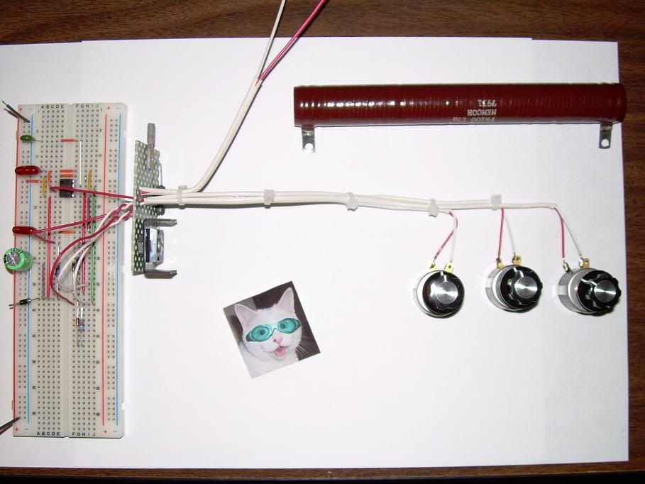
Well I got the rest of the parts yesterday to finish the first part of the RA circuit, it was getting really late last night and changing some things for looks and making sure that what I have is as close to what's needed for the group testing for data comparison. I still need to check everything but tonight it should be completed to start ..........
I'm still working on the "Borosilicate Glass Tube" resistor and had to order the correct "Ni Cr A" 80% nickel, 20% chromium wire because no one I could find had this particular size and type, drop shipped from the manufacture from the place I ordered it (Small Part's Inc.) will be next week before I receive it. The electrical connection terminations to the resistor is what the last item is which shouldn't be to much of a problem, the whole assembly when completed should have a maximum "working" temperature of 600 degrees F ...... cross your fingers.
Well I've been stretched every which way and tomorrow is more of the same.
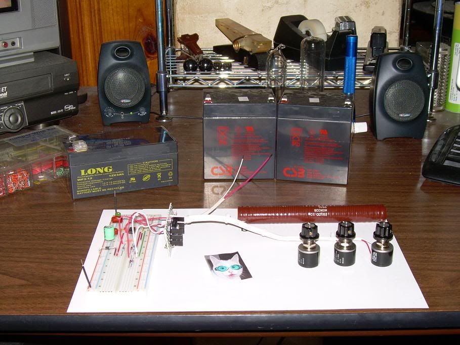
Still, I dusted off my 28 year old B&K 1476, dug out a gel-cell I had on the shelf for another project, made a trip to Radio-Shack and bought 3 10K 15Turn pots (They sell the tweaker tool there too, but I have a couple already), and finally got the ambition to fire up the timer circuit and see what the duty cycle looks like. I'm using my 'Proposed Changes' schematic and its working very well. I increased the 100K resistor to 150k to compensate for using a 10K pot, dialed that in perfectly at 2.5KHz. The other pot I left at 10K, so the max resistance for the 'On' time is 11K and really it looks like I'll be using that down on the lower end anyway. I decoupled pins 4 and 5 each with a .01nF cap to ground and my charge/discharge cap measures .003uF even though its marked .004
I still had an old NE555N from 1980 on the breadboard and it fired right up. But I don't like the output wave form, it has a small glitch at the end of the rising edge. So I will try the LM555 and the SE555 and see how they look. It's late, and I'm fatigued and that's how you blow up good HEXFET's so I am going to wait for tomorrow before I 'smoke' test this. I have some large resistors around here somewhere like the ones Aaron is using, so I'll probably find one that works and try that. BTW, plenty of control adjustment and no problems with inverted pulses. I'll be using a 100 ohm resistor between my output pot and the gate, so the minimum resistance to the gate will be 100 ohms. I may reduce this if I can't get oscillation, but from what Aaron has demonstrated it seems we need at least that much. I like to have the buffer in there to prevent burning the wiper in the pot if we're down on the low end.
Smoke. Did you know that all electronic parts run on smoke? As long as the smoke stays in, they keep working - but when you let it out... LOL
Also, I notice that in the schematic the one terminal of the pot is left floating. Electrically this is fine, but mechanically it can lead to strange adjustment behavior. This is because when rotating the wiper it can lose contact momentarily between windings and send the circuit off in an infinite mode. To help prevent this, sometimes we have the lose end of the pot tied to the wiper pin. This ensures that if the wiper floats for any reason, that the overall resistance of the pot is still in the circuit. This is more true in the older worn pots than new off the shelf items. It can also apply to carbon slide pots where dirt can cause the wiper to lift. For now, I have left the loose end floating.
Well hopefully I can find some time to post any results I have tomorrow, otherwise it will be Thursday (yes I know its 2:00AM Wed but it still feels like Tuesday night, besides its already tomorrow in Australia today ) My wife wants my time tomorrow (this) evening for an engagement she has tickets for and as much as she does for me I owe her much more than that.
Cheers,
Last edited by Harvey; 08-26-2009, 09:17 AM.
Reason: Fixing stuff, adding things etc - and people laugh when I tell them I'm a time traveller ;)
I've taken the trouble to post this from overunity.com as it's relevant to our circuit. Thanks very much for this Cat. Hopefully we'll hear more when the testing continues.
Rosemary
submitted by powercat
* we know enough to know we don't know enough
Re: Claimed OU circuit of Rosemary Ainslie
� Antwort #1396 am: August 25, 2009, 03:50:57 �
The concept from "hhoforvolts" appears to be a good one especially if you are using a higher amperage Mosfet like the ST Microelectronics "STW9N150"
N-channel 1500 V - 8 Amp PowerMESH� Power MOSFET with a Single pulse avalanche energy of 720 mJ http://www.st.com/stonline/products/...e/ds/13539.pdf
Just omit the 10 Ohm resistor and connect to the cell directy, there would be no need for a Pulse Width Modulator (PWM) for any possible run away cell amperage condition ...... great idea if it works and it just may.
Hi
I saw this Post and the video, funny, that he says, he could get the Timer circuit working with his first try.
Same as me, but i have to commit, some did give me a lot of wrong Impressions, that i couldnt say it 100%.
But my scope shot did say the same as his with the small On Time from the Mosfet.
The advantage from the latest one is, anyhow, it is slightly better to control,
but actually both work for me.
But i got the same Idea too, to use pulsed DC for HHO, i know some Builders, what do look for a Way to reduce the Input, what is mostly around 10Ah or more, to produce enough Gas, and thats still a bit much.
My Video is actually the latest Timercircuit, updated from Aaron, and i did rebuild it.
I did connect as load a pice of Wire from a oven, around 15cm/5,9in long,
and spiraled, without Core. _//////////////-
With this Pice of Wire i could flip the Spikes to negative one,
Seems i cant do it with a Microwavecoil, what is flat and quadratic.
But i suppose, more work with the Resistors with Ceramic core, and therefor,
they should could reproduce it too.
About the SK Transistors, it can be, that they produce better Spikes,
but it looks for me, they do lesser cycles, because they dont are avalanche rated.
But a practical Test would say more about, what is better under the Line after adjusting them.
Right now, i play with anything, to look for, what i can get out.
I tried something with a Torroid, to saturate it right/close, like i said in a earlier Post, to see, if i can get more Power for a heating Element.
The Tests with only the Wire, yes, it did heat up, but my Batteries been some weak,
you can maybe get a better Result with full loaded Sources.
One Thing was weird, one Battery only gets 10V,
and the second did drop down to this Voltage too, and stayed there, but still got over 20 Ah.
Seems like, they get parallel conditioned.
Therefor i think, it is importend,
that both Batteries are at good condition in series, and full charged, and able, to get to full Capacity.
I charged the better one again up, but it did take a while, till it did go over 10 V again,
even, that it still had couple Amps inside, like as if it did stuck there.
Right now, i got a few new Ideas, after rethinking about the Skalarfield,
even, where i am not sure, if its the Field outside, or the inner Balance or call it Zero Point Energy.
Now i redo some of my Coils from my Bedini SG, and got reminded again,
that its importend, to adjust any time, when you connect a new Batterie
to the Bedini Motor, you need to adjust it new, and look at the Amps from the Input.
It drops down half for the input with the right Settings at the Base with same high Output.
but i dont think, thats your Field, witsend
Today i stumbled over the TPU Thread at ou.com, where they have allready some successfull rebuilds,
and to make it short, very short, he/they says,
you need 3 Induction coils, what they feed with 3 different Frequencies.
With that, you can speed up the moving of the 'Electrons' at the Generatorcoil,
like, a Ball, what you touch once, will roll for a while.
Hit it in a certain Frequency, it will hold a certain speed,
hit it with faster Frequencies, it will very much more speed up.
But i think, that is a Way to get extended Heat, to make a Transformer,
and feed it with some some smaller induction Coils with some Frequencies, and hopefully, the output will increase.
And well, you see, saturate a Core with the Field seems is more like to redirect the Magnetic Field,
even, its not sure, if its the aligment of the 'Atoms', or more, the molecular connections are right,
and it can concentrate and bundle the Force, what do influence on them,
and something like the TPU works with the Vacuum without Core at the Coils.
And i am still not done with shaking my Head over some, who first really need a Proof,
if this Circuit work or not, They are so way beside the Track anyhow.
I've taken the trouble to post this from overunity.com as it's relevant to our circuit. Thanks very much for this Cat. Hopefully we'll hear more when the testing continues.
Rosemary
submitted by powercat
* we know enough to know we don't know enough
Re: Claimed OU circuit of Rosemary Ainslie
� Antwort #1396 am: August 25, 2009, 03:50:57 �
Hi Joit. I enjoyed your video. Rather wished you'd talk us through it though. And I'm still not sure which circuit you're working on. TK says your testing some really big transformers? Is he right?
I just uploaded a new video but it is not quite related to this topic or my coil flyback re-circulating topic. It is related to Resonance therefore I posted it in my Resonance topic. If anyone knowledgeable can help explain why I'm getting the results I am in the video demo please post your explanation in that topic so not to disturb this one.
Another small Video from me for adjusting the Circuit,
you see there, when the Spikes flip and the ON Time is at top, it is, what you need, or the Voltage goes down.
Probe is at Minus to Minus Source, and Drain.
I do not have a special Setup now, just playing around with a spiral Wire from my Heating element, which did fall apart ,
so nothing special to see.
Batteries are not full charged and one only gives 10V, till its fixed.
And sorry for the bad Quality, lol.
End Voltage after 15 Min settle down 18,53 with produced Heat in the Wire,
and in the Transistor.
Figure, when the Scope would be 3d, what the Line would look like,
because actually its a spiral Form, not only up and down.
EDIT:
I only have a few minutes here but I thought some clarification was in order:
f = frequency in Hertz
π=pi=3.1415926535897932384626433832795
L = inductance in Henries
C = capacitance in Farads
(note that it is not micro, or milli but full Henries and Farads)
Last edited by Harvey; 08-25-2009, 01:08 AM.
Reason: Clarification of terms
A pure inductor will return 100% of the power provided to it - they don't exist. This is why inductive components are not rated in watts, but instead they are rated in Volt/Amps. A watt infers that power has been dissipated whereas a Volt/Amp infers that power has been moved. The inductive portion of your load resistor tends to work in that way, attempting to return the energy, that is the ringing. When current flows through an inductor, it builds the magnetic field until it is saturated and can build no more, at that point the current flows through as if it were just a wire. When the current stops flowing through, the field attempts to keep it going by collapsing in on the wire. If there is a path, then current will flow until the field is fully collapsed. But when there is no path for the current to flow, all that energy is converted to voltage across the terminals of the inductor. Theoretically, the field is infinite and the voltage is infinite, but since a perfect inductor does not exist, neither is true, but the voltage will be quite high.
End quote:
This may tend to look a little off topic but is something that I feel should be addressed. The ring is what I am refering to. For one pulse to the circuit, there are many rings after until it dies out or is pulsed again. How do you calculate that ringdown frequency? To make it simple use a parallel cap/coil for reference. Say you had a 10uh and 10mf cap.
The reason I am asking this is I feel it lends to the way the circuit achieves what it does.
I'm going to see if I can find the wire local here in the Portland, Or area before I buy some off the net
Best Regards,
Glen
Hi Glen,
just to let you know. Nichrome wire is used in plastic shrink wrap equipment to cut and seal 2 layers of plastic. A few months before this topic started my brothers business was closed down and he had a few spools of this stuff I could of got for free
Harvey - many thanks for the explanations. Will need to 'plod' through them but at least I'm closer to understanding this. I think, at it's least, Eskom should 'open' their meters to let us return something. The trouble with our country is that it has 1st world pretensions - 3rd world conditions and monopolists owning the most of it.


 ) My wife wants my time tomorrow (this) evening for an engagement she has tickets for and as much as she does for me I owe her much more than that.


Leave a comment: