Announcement

Collapse
No announcement yet.

COP 17 Heater | Rosemary Ainslie

Collapse
This topic is closed.
X
This is a sticky topic.
X
X
 
  • Filter
  • Time
  • Show
Clear All
new posts

  • Take a Pill Guys

    If you recall 20 or 30 pages ago, THE testing to put this matter to bed was going to be performed by Aaron and Peter. This was clearly understood by all, and stated as such. The test protocol etc. was written, test sheets done and then it was a matter of waiting for the scope so the tests could be run. Remember?

    Now, if y'all want to replicate, that's fine, but unless everyone uses the exact same circuit and parts, and test protocol, comparisons aren't valid. Capish?

    It was clear from the beginning that Aaron's circuit and tests of the RA circuit was the focus. I was simply asking about the progress, and when we can expect to SEE the test results. Aaron and Peter should also write up a conclusion about the results, and denote the test procedure used.

    I gather that either the testing is not complete, or the data analysis is still on-going, or both. OK. Thanks for the update.

    .99

    Comment


    • >Many many folks would like to put to bed the Ainslie claims one way or the
      >other based on your evidence, so we're all waiting patiently.

      What do the Terms 'We' and 'Many' means again ? It seems like you do mix there up something.


      >If you recall 20 or 30 pages ago, THE testing to put this matter to bed was
      >going to be performed by Aaron and Peter. This was clearly understood by all,
      >and stated as such. The test protocol etc. was written, test sheets done and
      >then it was a matter of waiting for the scope so the tests could be run.
      >Remember?

      Not True. You did actually waiting, The scope was actually for his own Entertaniment,
      not to show you Naysayers the correct Waveform, what they couldnt belive or figure out.
      But not for you Guys to please you.

      Even I have no Idea how Peter Lindeman should be involved into this here.
      Are you Dreaming?

      >Now, if y'all want to replicate, that's fine, but unless everyone uses the
      >exact same circuit and parts, and test protocol, comparisons aren't valid.
      >Capish?

      Nonsense. When someone can rebuild it with a different Resistor and can get the same Results,
      or make a Improvement, Why should that not be valid.
      There are more Examples for an use of the Circuit, Remeber?

      If you did really read back, then you showed again clearly, that you only read what you want to read.
      The Answers in the Post SHOW, that there is a Gain and you can produce more Heat as in the usual Way.
      What is so hard to get there??? I would more appreciate,
      when one from the Naysayers would come up with a direct comparison
      of, how much Heat is produced in a normal Way with 24V, and how much Energie is wasted, compared to a pulsed Circuit.

      That would be a really nice Experiment, when you really could see once,
      how much Heat you can do with 24V and for how long.
      But let me guess, with 24V and a 10 Ohm Resistor, Uhmm Zero Heat?

      Wonder, what is there so hard to understand, but of course,
      when someone only see, what he want to see.
      Ah, maybe its, because Peoples, what do all theoretically, need theoretically Datas,
      that they can understand a little Piece of something.
      Wonder, if you put at afternoon a note beside your bed,
      'First thing after wakeup, open Eyes, and go pee, when i must'

      When you look for Tables, then look at the Quantum Article, they are allready there and valid.
      And it been more then once confirmed here, that they are valid,
      surely, they wont be exact the same for anyone,
      but maybe thats your Point when you are petty-minded.

      For the many many other Peoples what are waiting for Results, tell them,
      to put them to Bed. it has anyway no sence for them, to waiting on it.

      Or is here at the Forum actually someone who is waiting wistful for the Table of Results,
      before he go to rebuild it.
      Anyone?


      PS. When you really did put me on the Ignorelist, then it shows once more,
      what a chicken-hearted Fellow you are.
      Theorizer are like High Voltage. A lot hot Air with no Power behind but they are the dead of applied Work and Ideas.

      Comment


      • Oh, yeah wait. They are awaiting a COP17*24V=408Volts nonstop spitting Perpeduum Mobile
        with hundret of Amps and Watts, and beside heating a little Resistor up.
        Sure then, why they do wait at it.
        Theorizer are like High Voltage. A lot hot Air with no Power behind but they are the dead of applied Work and Ideas.

        Comment


        • Ok, some calculations, but hum, maybe better not.

          To heat up 1Kg/1ltr Water 1 more Celsius, you need a Power of 4188(4200) calorie.
          4188 cal = 4,87 Watt/second.
          A 12V/10Ah Batterie should heat up 1 Ltr Water for 10 Celsius then for 3 Hours.

          Or a other Example, when you connect a 10 Ohm Resistor into a 24V Circuit,
          then there runs a max Current of 2,4Ah equals 57,6 Watts/sec.
          And that is, what you are blowing out, when you connect it the normal Way.
          Theorizer are like High Voltage. A lot hot Air with no Power behind but they are the dead of applied Work and Ideas.

          Comment


          • Hi Joit. Have been rolling with laughter. I see a liberal exercise of your rights to freedom of expression. When it comes to protecting our flanks, it seems to inspire the passions and their expression. Where has that mild philsopher gone? What fun. I cannot tell you how much I enjoy your posts. They're an art form. I have printed nearly every post you've written for this thread. Such a fan.

            Poynt - can you to please advise regarding the energy in that 'spike'. Is there a marked discrepancy regarding the sim predictions and actual voltage? Or are we in the same ball park? I've heard so many contradictory predictions regarding this am no longer sure which is classically correct.

            And could you PLEASE advise me personally on a question. TK did a video Electric OU:Comparison of Current Monitor Positions; Isolated Input Fluke-O-Scopy. I keep asking him about this? He claims an increase in voltage over a 10 minute? run - with load. How typical is this and is there any allowance in mainstream for the recharge? I'm just trying to tidy up my understanding of what is allowable in terms of classical theory. If you could oblige here I'd be very grateful.
            Last edited by witsend; 08-24-2009, 12:17 AM.

            Comment


            • 10 OHM - Resistor

              Originally posted by poynt99 View Post

              Now, if y'all want to replicate, that's fine, but unless everyone uses the exact same circuit and parts, and test protocol, comparisons aren't valid. Capish?

              .99
              Hi everyone,

              A parts up date ...... as far as I can tell "no one" has sourced or acquired the 10 OHM resistor in the RA circuit -

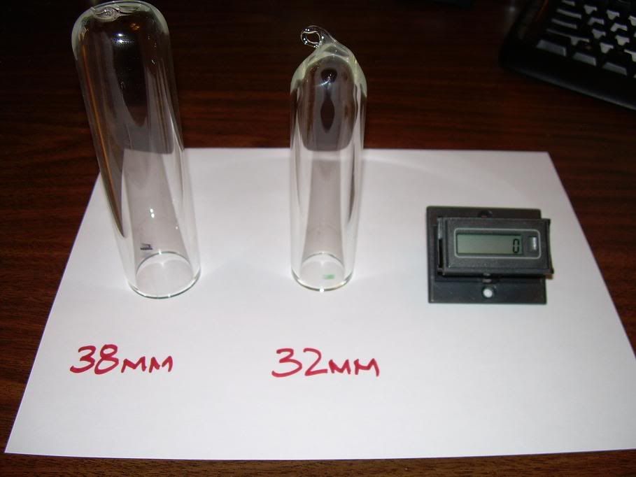
              The load resistor was made by Specific Heat CC (SA). It comprises a 10 ohm hollow core wire wound ceramic structure with a length of 150 mm (5.9055 in long). and a diameter of 32 mm ( 100.5308 mm / 3.9579 in
              circumference ). 48 turns of resistance wire (4825.4784 mm / 189.9795 in / 15.8316 ft long) are spaced at 1 mm. It was chosen for its inductance (8.64 micro Henries).


              I have sourced a resistor similar to Aarons and will be getting it Monday or Tuesday for group data comparison ....... BUT ....... being my son is a "glass blower" I have access to this .......


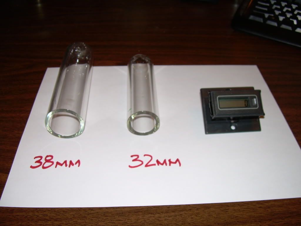
              I will be "MAKING" the proper one using the following parts which should be more than adequate for this replication -

              "Borosilicate Glass Tube" ( Pyrex )

              32 mm OD. x 26.4 mm ID. ( w/ 2.8 mm heavy wall )


              SAMPLE MATERIAL'S (for reference)


              "Counter Totalizer"
              Durant - Part Number E402400

              "Nichrome Wire"
              10 ohms @ 15.8316 feet = .63165 ohms ft

              AWG 20 [.032 dia] ( .6592 ohms ft ) = ( 10.4362 ohms ) "Ni Cr C" 60% nickel, 16% chromium, 24% iron

              AWG 20 [.032 dia] ( .6348 ohms ft ) = ( 10.0499 ohms ) "Ni Cr A" 80% nickel, 20% chromium

              If anyone is interested or have comments please feel free .....

              Best Regards,
              Glen
              Last edited by FuzzyTomCat; 08-23-2009, 08:58 PM. Reason: circumference not diameter on 32 mm measurements
              Open Source Experimentalist
              Open Source Research and Development

              Comment


              • 20awg wire coil

                Glen,

                The 15.83 feet at 20awg is what I have found to be the wire need to match the resistance of 10 ohms at that length.

                The quantum article dimensions seem to show 12awg if there is 1mm between each winding. But then the resistance would only be about 1.5 ohms.

                I'm interested in 20awg nichrome wire for an experiment wound at 32mm diameter and 150mm long.

                Are you going to sell these coils pre-wound on the glass? If so, I want to buy one.
                Sincerely,
                Aaron Murakami

                Books & Videos https://emediapress.com
                Conference http://energyscienceconference.com
                RPX & MWO http://vril.io

                Comment


                • Originally posted by Aaron View Post
                  Glen,

                  The 15.83 feet at 20awg is what I have found to be the wire need to match the resistance of 10 ohms at that length.

                  The quantum article dimensions seem to show 12awg if there is 1mm between each winding. But then the resistance would only be about 1.5 ohms.

                  I'm interested in 20awg nichrome wire for an experiment wound at 32mm diameter and 150mm long.

                  Are you going to sell these coils pre-wound on the glass? If so, I want to buy one.
                  Hi Aaron,

                  I'm in the preliminary stages of this and discussing with my son on methods to adhear the Nichrome wire to the Borosilicate Glass Tube to make the windings stable at the temperatures. It appears the melting temperature for the Borosilicate Glass and the Nichrome is very close to the same which is good because we should never reach it.

                  This is one of those weird things I actually dreamed about doing last night and woke up this morning with ....... weird ....... but it will work !!!

                  I'm going to see if I can find the wire local here in the Portland, Or area before I buy some off the net ...... this can from my impressions be used for more than the RA application and will keep totally you posted on its progress stages. The Borosilicate Glass Tube it appears my son has about 15 feet of it "on hand" now.

                  This should be good

                  Best Regards,
                  Glen
                  Open Source Experimentalist
                  Open Source Research and Development

                  Comment


                  • Originally posted by witsend View Post
                    Poynt - can you to please advise regarding the energy in that 'spike'. Is there a marked discrepancy regarding the sim predictions and actual voltage? Or are we in the same ball park? I've heard so many contradictory predictions regarding this am no longer sure which is classically correct.
                    The simulation and real life results are very much in the ball park. The MOSFET model is quite influential to the results, and from what I've seen, the model in my SPICE package for the IRFPG50 is not the best in terms of matching Aaron's results exactly (then again, I am not using his exact inductor either). Don't take that as a reason to invalidate the results though. There are several subtleties to this circuit that have significant effects on the spike amplitude and ringdown characteristics. Just ask Aaron what happens when you touch the load while the circuit is operating.

                    And could you PLEASE advise me personally on a question. TK did a video Electric OU:Comparison of Current Monitor Positions; Isolated Input Fluke-O-Scopy. I keep asking him about this? He claims an increase in voltage over a 10 minute? run - with load. How typical is this and is there any allowance in mainstread for the recharge? I'm just trying to tidy up my understanding of what is allowable in terms of classical theory. If you could oblige here I'd be very grateful.
                    I have shown by simulation that at least 50% of the used energy can go back into the source battery or capacitor. How this translates into increased voltage on our source battery is a bit of a mystery, and I am not certain if this is known in mainstream science.

                    Certainly, if the battery voltage does indeed increase over a 10 minute period, the obvious question would be: Under load, does this increase in voltage persist for at least 10 minutes?

                    Until someone can show that it does, it's remains only a curiosity.

                    .99
                    Last edited by poynt99; 08-23-2009, 10:57 PM.

                    Comment


                    • Answering Poynt here

                      You're right about strange happenings when Aaron touches the circuit.

                      Many thanks for the explanations. I can't see how increase in battery voltage can reconcile with classical - but I hear you. If it only happens now and then in a run - presumably it can be attributed to some vagary associated with battery chemsitry?

                      But here's the next question. What if a switching circuit is applied to a utility supply source precisely to return energy to the grid? To the best of my knowledge the average utility watt meter won't recognise a 'returning' cycle? Can you comment here? I'm supposing that a a switch is applied to a dc rectified current and that the same spikes are generated? Would this argument be 'bought' by utility suppliers as 'returned' energy?
                      Last edited by witsend; 08-24-2009, 12:19 AM.

                      Comment


                      • Whether the increased battery voltage "sticks" or not is the question. If it does, then you've maybe got something.

                        Regarding your last question, I'm not quite sure what you are asking exactly. The grid, DC, and spikes? Please explain what you are asking, thanks.

                        .99

                        Comment


                        • Hi everyone,

                          After the testing is completed on the common RA replication build, I will be making my Borosilicate Glass Tube, 10 Ohm resistor to the available specifications -

                          The load resistor was made by Specific Heat CC (SA). It comprises a 10 ohm hollow core wire wound ceramic structure with a length of 150 mm (5.9055 in long). and a diameter of 32 mm ( 100.5308 mm / 3.9579 in circumference ). 48 turns of resistance wire (4825.4784 mm / 189.9795 in / 15.8316 ft long) are spaced at 1 mm. It was chosen for its inductance (8.64 micro Henries).

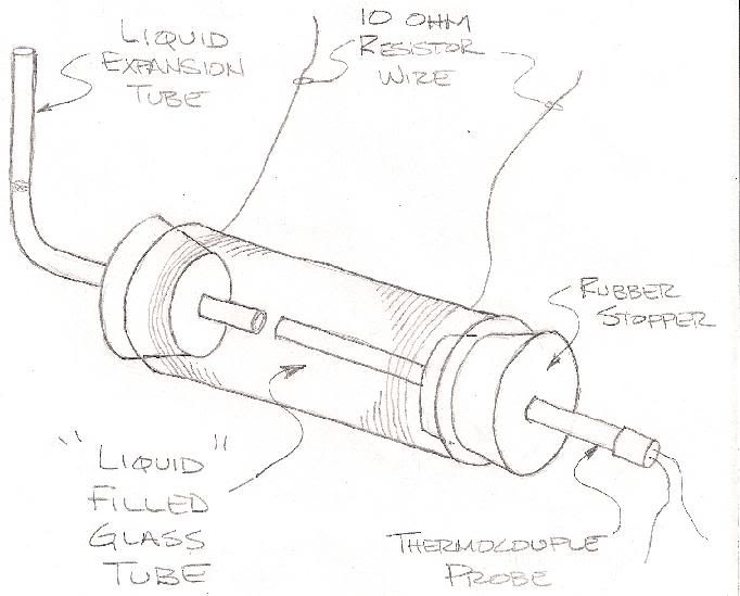
                          The testing method for temperature I have envisioned a way of using the tube itself as part of the measuring device -


                          I'm not to sure what the maximum temperature will be so the liquid inside the tube is up in the air right now until some information is obtained. This device will more than likely be in some containment container for any accidental spillage of the liquids used. Any comments or further ideas would be appreciated especially fluids that could be used over 212 F or 100 C with out any damage to the fluid.

                          Best Regards,
                          Glen


                          --------------------------------------------------------------------------
                          EDIT- There is no copyright on this from me "anyone" wanting to use this Open Source information for any replications ....... Please, feel free to do so !!
                          Last edited by FuzzyTomCat; 08-24-2009, 05:03 AM.
                          Open Source Experimentalist
                          Open Source Research and Development

                          Comment


                          • Originally posted by poynt99 View Post

                            Regarding your last question, I'm not quite sure what you are asking exactly. The grid, DC, and spikes? Please explain what you are asking, thanks.

                            .99
                            sorry Poynt. Let's try this again. One can, theoretically, apply the switching ciurcuit to utility supplies. One would then get the same effect, those same spikes that may recharge. Let's assume that the supply source, like a battery, supplies an excess to what is used. The switching circuit system then kicks back the energy. In our watt meters here in SA they are installed by Eskom and this potential for returning energy is physically blocked by hardware in the meter. My question is this. If this energy is known to be 'returnable' and if, also the watt meters are opened to allow this returning energy - and if, indeed, the 'spike' can be modified back to the supply frequency and AC 'shape' - then why not encourage it? I am not necessarily arguing that this is extra energy at this stage. Only that it is unused and could be returned to the grid.

                            Comment


                            • Late Start

                              It's 1:35 AM and I am just now getting some time to myself to work on this a bit. Checking in, as it were, here first. See that I have missed quite a bit over the last day or so.


                              Glen, on the glass, make sure you allow for the thermal expansion, it will get hot fast and if the thermal conduction is too low you will get uneven expansion leading to fractures which lead to breaks in the thermal conduction which destroys the test in short order. The wire and the glass and the adhesive need to 'grow' together as much as possible during the expansion. Separate growth rates lead to problems unless expansion material is included.

                              Aaron, the 10K 10-turn pots from Radio Shack could be used by padding either side of them with 22K resistors as needed, or removed entirely if the desired resistance is below 10K. This gives a much better resolution of 1K per turn rather than 5K per turn but does require a course tuning by fixed resistance. I did see some 50K 10-turn trim pots online - could have been at Quest, don't recall. But a dual pot setup could be used also, for course and fine adjustment.

                              .99, getting a good battery model in spice would be a worthwhile endeavor. The voltage or current sources supplied generally don't allow changes in the source. Some sort of conditioner between the source and the circuit may be the ticket. Perhaps a series diode, resistor, and inductor feeding in and out of a rather large filter cap to simulate the battery impedence for the 140K - 250K frequency range. This would then allow the back EMF to recharge the cap similar to what we see in the real life battery. I don't know if we are going to be able to get the simulator to self trigger and produce the Hartley type oscillations. I tried a variety of approaches including capacitive feed back to the gate etc. with no joy. It is possible that we are inflecting the 555 ground circuit badly enough that the negative rail for the 555 is above the off threshold for the gate - hard to tell. Putting an inductor between the 555 ground pin and the simulator ground source may allow the similator to do that. I am only thinking out loud here as we have not yet conclusively determined from where the oscillation originates from.

                              Rosemary,
                              Power that is sent back to the grid is done with phase transformers or synchronized inverters. When the extra energy is present on the line it will flow to where the demand is, either local or back past the meter into the grid. The meter may or may not react to a back flow of power. Here in the states, the meters will run backwards and deduct from the readings. Our local energy companies will not buy the energy back, but they will extend credit against future energy use. The spikes in this circuit are very narrow but there are a lot of them during the oscillation periods. How much power they contain is still a matter of the calculations. Classically, they will not contain any energy that wasn't already provided. A pure inductor will return 100% of the power provided to it - they don't exist. This is why inductive components are not rated in watts, but instead they are rated in Volt/Amps. A watt infers that power has been dissipated whereas a Volt/Amp infers that power has been moved. The inductive portion of your load resistor tends to work in that way, attempting to return the energy, that is the ringing. When current flows through an inductor, it builds the magnetic field until it is saturated and can build no more, at that point the current flows through as if it were just a wire. When the current stops flowing through, the field attempts to keep it going by collapsing in on the wire. If there is a path, then current will flow until the field is fully collapsed. But when there is no path for the current to flow, all that energy is converted to voltage across the terminals of the inductor. Theoretically, the field is infinite and the voltage is infinite, but since a perfect inductor does not exist, neither is true, but the voltage will be quite high. This high, very transitory voltage has and electrochemical reaction in the battery. For a brief instant, the battery post will be at that potential and free electrons in the acid will accumulate at the positive terminal internally, but when the voltage collapses, those electrons are pushed away toward the negative terminal. This rapid back and forth disturbance in the chemicals can encourage other electrons to become free and accumulate at the negative terminal in a condition known as 'overcharging' where we get a larger charge than would normally be possible from the chemical reactions alone. This would be a true usable and persistent charge. Another effect that can occur is where the energy never actually affects the acid. Instead, the battery post acts as an ion collector and only the surfaces of those nearby plates and post material have a static charge on them. The charge has no depth in this case and is easily depleted - this is the 'fluff' that has been hashed about of late. Either condition could be true in your circuit - it really depends on the dynamics of the battery and the resonance of that portion of the circuit.

                              Bleagh - after several interruptions, it is now 2:40A and I am exhausted - the construction will have to wait till tomorrow.

                              "Amy Pond, there is something you need to understand, and someday your life may depend on it: I am definitely a madman with a box." ~The Doctor

                              Comment


                              • Harvey - many thanks for the explanations. Will need to 'plod' through them but at least I'm closer to understanding this. I think, at it's least, Eskom should 'open' their meters to let us return something. The trouble with our country is that it has 1st world pretensions - 3rd world conditions and monopolists owning the most of it.

                                Comment

                                Working...
                                X