Announcement

Collapse
No announcement yet.

COP 17 Heater | Rosemary Ainslie

Collapse
This topic is closed.
X
This is a sticky topic.
X
X
 
  • Filter
  • Time
  • Show
Clear All
new posts

  • Originally posted by eternalightwithin View Post
    I agree with poynte99. Funny I was thinking about this late last night. I had the feeling that if one wants to get any appreciatable amounts of power out of this thing, we're going to have to change the 555?

    What about a VCO? You could take a noise source in avalanche mode and attached it to a schmitt trigger. Add a shift register, say 12-bits, and a DAC. You got your self a random signal generator.

    That clock signal would be attached to a comparator and... how do you say it charge pump? Attach "charge pump to your mosfet.

    More discrete than all that crammed into your 555
    If you look around you will see where I have already driven the HEXFET with a triple gate dual inversion from a CD40106BCN. The 555 outperforms it significantly. Also, aperiodic oscillation was impossible.

    The problem with these approaches that have been suggested is phasing. The aperiodic operation is so efficient because it is driven by the inductor itself rather than the other way around. The controls are properly phased in harmonic synchronization even though they are firing on different harmonics throughout its range.

    If I were to set out to eliminate the 555 from the circuit I would first have to identify how that feedback is occurring if I wish to duplicate it in the proper phase. As I have said before, this still has to be ascertained. I have even tried an inductive feedback into the timer to see if I could get it to sync up and allow the use of unloading the gate so badly. This action is a symbiotic reaction between the FET and the 555 and my tests last night hint that impedance is necessary on the return path to the battery.

    If we knew specifically the fundamental resonant frequency of our load, we could then create a random pulse generator that selects any of the harmonics and fires a few pulses at that frequency. The pulse width can remain the same, it only needs to be as long as is necessary to charge the inductor. Then we could ensure nice clean steep FET operation at an aperiodic phase sync'd manner. But alas, the dynamics of the inductor change with temperature and other factors. It's resonant frequency shifts. So now we are getting into PLL resonant amplitude detection circuitry all of which we are adding in just to eliminate the 555. What is the old adage, if it works don't fix it? And KISS, keep it super simple?

    "Amy Pond, there is something you need to understand, and someday your life may depend on it: I am definitely a madman with a box." ~The Doctor

    Comment


    • Originally posted by witsend View Post
      We've been disconnected since 6.00am. Cable theft. One of the consequences of our 3rd world conditions is that it's viable to steal copper from our utility supplier. But that theft is now encroaching into our cities and suburbs. Extraordinary.

      In any event - I read through Harvey's analysis of Poynt's clashes with me - or is it mine with him? The truth is I'm getting way too used to saying what I want instead of what I aught. Yet again apologies Poynt. This is getting tedious, but I solemnly undertake to do better. And it's not you who's the obsessive compulsive. It's me. I think the term is projection.

      Harvey - you're our very best find. Not only that first class brain but all that wisdom. We need some urgent cloning - that way you could share the burden and maybe get some 'off duty' time.
      Thank you for the kind words Rosemary

      Sorry to hear about the copper loss. A few years back we had a fellow tie his truck to a trunking cables in an underground vault he accessed via a manhole cover in the street. He ripped loose and absconded with over a mile of cable IIRC. It was suspected that he was a disgruntled employee, I never heard how that one turned out.

      "Amy Pond, there is something you need to understand, and someday your life may depend on it: I am definitely a madman with a box." ~The Doctor

      Comment


      • Originally posted by FuzzyTomCat View Post
        @ Rosemary and Harvey,

        Rosemary did you use a heat sink on the Mosfet in your original models ?

        Harvey have you seen TK's new video of a modified RA circuit ?

        YouTube - Electric OU: Properly Switched MOSFETS Produce More Power Gains than the Ainslie Circuit

        I noticed in the opening shots that TK's Mosfets are insulated from the heat sink and in this PDF .....

        A Combined Single Pulse and Repetitive UIS Rating System

        There is a statement on Schematic page 3 "Obviously the heat sink is more of a problem than the UIS capability"

        Could the heat sink be adding something unwanted or a problem in the circuit ... I'm just one for small details and that rock that no one looked under.

        Best,
        Glen
        What showmanship! And....'keep watching' the show will get better! It's a shame he feels such a strong need to have his back patted as frequently as he does, but then that's just who he is - I like him the same anyway. With all that schooling and edumacationistischolarlylike training I wonder why he missed the dual current flow in the ainslie circuit... It's easy to overlook things when your mind is made up and you don't want to be confused by the facts I really do admire his craftsmanship though


        EDIT: Regarding the heat sink. You have 3 choices here - bond it electrically to the drain, isolate it and tie it to a potential like ground, isolate it and let if float. In the first case you risk the heat sink acting as an antenna and dumping stuff onto the drain. In the latter two, you have to deal with the capacitance formed between the drain tab and the heat sink and how that may interact in the circuit. I think if you ask TK you will find that insulating them was not his goal, but rather it had more to do with the ease of using a sil-pad for heat transfer.
        Last edited by Harvey; 09-06-2009, 12:49 AM.
        "Amy Pond, there is something you need to understand, and someday your life may depend on it: I am definitely a madman with a box." ~The Doctor

        Comment


        • Originally posted by witsend View Post
          Hi Fuzzy. Yes we did use a heat sink. Hope that helps.

          EDIT by the way - I saw that link earlier. What do you think? Jibbguy thinks it's another example intended to sucker us into believing it with the actual intention to point out that we're idiots to believe he claimed overunity. Not sure of the energies involved and he's not telling. Typical.
          That video has no intention of supporting OU. Tesla's coils like the one shown have been rigorously tested and shown to work inside of the conservation laws - TK knows this and that is why he is trying his misdirection here.

          For a better demonstration let's compare a 40W fluorescent lamp to a 7.2W plasma ball:

          YouTube - Physics Plasma Ball lighting up fluorescent tube

          Now, the important thing to note here is that the plasma ball doesn't diminish in function while doing the 'work' on the lamp. Is there a full 40W being shown? The lumens appear comparable, but it is doubtful that the energy is really happening in that way. How would we test it to be sure?

          "Amy Pond, there is something you need to understand, and someday your life may depend on it: I am definitely a madman with a box." ~The Doctor

          Comment


          • Harvey,
            about the Timer,
            i played today again a bit around with 2 Coils around a Torroidcore, had the Coils connected like this.
            -> 12V/0,20Ah Plus at both Coils.
            Same Plus -> Diode - 2 timer.
            2 Coils switched with 2x 2n3055, each Base triggered from one of the Timers, and 10W Pot before Minus.
            I put my Scope at both C- Pins from the Tranistors, and got the same frequency there, no matter, wich Timer i did adjust.
            I promise. that classical View stinks, because i think, its more with the Minus controlled and triggered, as with the Timer itself.

            A other Thing did show, as i measured the max Frequency of a Timer, running it without a load, and it was max at 160 khz. When i did connect the Load with the Mosfet, i could get 190 khz, so its not only the Timer, seems.
            You 'could' maybe say, the backspikes mess something around in there, that some Energie left in there, but i think, its not only the Timer, what cause this behaviour.

            Fuzzytomcat, btw, with the bumbler, i meant noone from this Forum here,
            but, you-know-whom, with his oh soo smart comments.
            Theorizer are like High Voltage. A lot hot Air with no Power behind but they are the dead of applied Work and Ideas.

            Comment


            • Originally posted by Harvey View Post
              How would we test it to be sure?

              Feed back into a Cap like some Experts suggests ?

              Seriously, i think even more, that i would be glad, if he COULD finally figure out once, that you can do more as only <100%.
              But i think, someone could still have Problems, to feed this HV back into a Circuit effectively,
              looks like, it has a very high Frequency, probatly with unpoled Caps like Tesla did.
              And it only can help to have an overall Progress, when everone could add a Pice for a big Cake.
              But i have no Comments anymore since what he have showed at past.
              Theorizer are like High Voltage. A lot hot Air with no Power behind but they are the dead of applied Work and Ideas.

              Comment


              • Ahh. Touché

                I was looking at timers. All are under 1Watt.
                I noticed the CMOS version could take up to 1.2Watt though. National Semi version. Might have to try that once I get my scope set up.

                David

                Originally posted by Harvey View Post
                If you look around you will see where I have already driven the HEXFET with a triple gate dual inversion from a CD40106BCN. The 555 outperforms it significantly. Also, aperiodic oscillation was impossible.

                The problem with these approaches that have been suggested is phasing. The aperiodic operation is so efficient because it is driven by the inductor itself rather than the other way around. The controls are properly phased in harmonic synchronization even though they are firing on different harmonics throughout its range.

                If I were to set out to eliminate the 555 from the circuit I would first have to identify how that feedback is occurring if I wish to duplicate it in the proper phase. As I have said before, this still has to be ascertained. I have even tried an inductive feedback into the timer to see if I could get it to sync up and allow the use of unloading the gate so badly. This action is a symbiotic reaction between the FET and the 555 and my tests last night hint that impedance is necessary on the return path to the battery.

                If we knew specifically the fundamental resonant frequency of our load, we could then create a random pulse generator that selects any of the harmonics and fires a few pulses at that frequency. The pulse width can remain the same, it only needs to be as long as is necessary to charge the inductor. Then we could ensure nice clean steep FET operation at an aperiodic phase sync'd manner. But alas, the dynamics of the inductor change with temperature and other factors. It's resonant frequency shifts. So now we are getting into PLL resonant amplitude detection circuitry all of which we are adding in just to eliminate the 555. What is the old adage, if it works don't fix it? And KISS, keep it super simple?

                Comment


                • Originally posted by Harvey View Post

                  EDIT: Regarding the heat sink. You have 3 choices here - bond it electrically to the drain, isolate it and tie it to a potential like ground, isolate it and let if float. In the first case you risk the heat sink acting as an antenna and dumping stuff onto the drain. In the latter two, you have to deal with the capacitance formed between the drain tab and the heat sink and how that may interact in the circuit. I think if you ask TK you will find that insulating them was not his goal, but rather it had more to do with the ease of using a sil-pad for heat transfer.
                  Hi Harvey,

                  I think your right about the antenna, if you check between the Mosfet Drain and the Mosfet back plane that the heat sink attaches to they are connected internally I also found some information on insulators for heat sinks ...

                  Heat Sinks

                  And then the Wiki ...

                  Mica insulator - Wikipedia, the free encyclopedia
                  Quote:
                  Heat sink insulation can also be necessary to prevent the heat sink from acting like an antenna if the component is connected to a rapidly varying signal.

                  The Question is the aluminum bar stock Aaron used for the last circuit addition "Ainslie-Murakami Negative Dominant Waveform Generator" I'm working on how was that Mosfet Connected to the Heat Sink bar ??

                  I couldn't find just the Mosfet insulators at the electronics store but found several packaged with some semi conductors ( high speed switching ) .... I got one of each because the insulators are the same for a TO-220 or TO-247

                  http://www.nteinc.com/specs/500to599/pdf/nte597.pdf
                  http://www.nteinc.com/specs/200to299/pdf/nte241.pdf

                  Glen
                  Open Source Experimentalist
                  Open Source Research and Development

                  Comment


                  • Hi everyone,

                    If you don't have a Mica Insulator or equal between your Mosfet and Heat Sink ..... YOU NEED ONE !!

                    And use Non Conductive heat sink paste if needed for the type of Insulator used !!!!


                    Glen
                    Open Source Experimentalist
                    Open Source Research and Development

                    Comment


                    • Harvey,

                      As a first kick, you're possibly taking a rather complicated approach. The wild oscillation mode may indeed be the result of a complicated feedback and phasing process, but the end result seems to be high frequency carrier that is either pulsed or varying in frequency, or both.

                      However, I would suggest that someone try a straight forward HF drive as a first step. Without trying this first you'll not know if this is all that may be required. KISS indeed. The 555 can create an aperiodic oscillation, but is the aperiodic part necessary to obtain the observed effects? Was a frequency sweep tried at any point?

                      btw, I was not suggesting that a CMOS inverter would drive the MOSFET better than a 555 would, but it seems you got that impression. The 555 is capable of much more current drive.

                      .99

                      Comment


                      • Why the mica? I was going to just use a little Ceramic or Diamond based paste.

                        David

                        Originally posted by FuzzyTomCat View Post
                        Hi everyone,

                        If you don't have a Mica Insulator or equal between your Mosfet and Heat Sink ..... YOU NEED ONE !!

                        And use Non Conductive heat sink paste if needed for the type of Insulator used !!!!


                        Glen

                        Comment


                        • Originally posted by eternalightwithin View Post
                          Why the mica? I was going to just use a little Ceramic or Diamond based paste.

                          David
                          Hi David,

                          I guess as long as there is no resistance between the drain on the mosfet and the heat sink you'll be Ok ..... but there is a substantial difference in the wave forms with the mica in between with full insulation now. I was using silver heat sink paste before and the Mosfet is now running hotter, between 110 - 120 degrees F, the 555 timer switching is much cleaner now ..... I'll be posting photos of the wave forms a little later tonight.

                          Glen
                          Open Source Experimentalist
                          Open Source Research and Development

                          Comment


                          • Harvey - I watched that video on the plasma ball. I'm utterly intrigued. I'm now going to have to read up more about this. I keep seeing more and more interest in plasmas. Such a sweet teacher - and teaching in English. I presume he's in India. Curious to know if English is the standard teaching languague medium.

                            And Fuzzy - can't wait to see the videos, but have to. It's Sunday and that calls for a meeting of the clan. But I'll log in again soon and watch it all later. I've spent some time here deleting posts from my PM folder which was at it's capacity limit. By the way, it's typical of your thoroughness that you thought to insulate the sink. I'm afraid we never did or not that I remember anyway.

                            By the way, I asked TK to give me a power analysis and he advised me to 'grow up' and 'move on' like he's done. His advice here gave me a small reminder of my youth. But unhappily, it seems that any question related to actual measurements is also proof of immaturity. Which - if true - makes his own maturity excessively advanced. I keep seeing echoes of Don Wilson's effect in what he's now plugging. But I'm second guessing his motives to death here. Perhaps he just wants to get back into proving his facility with the 'wow' factor.

                            Comment


                            • You Tell Me ??

                              Hi everyone,

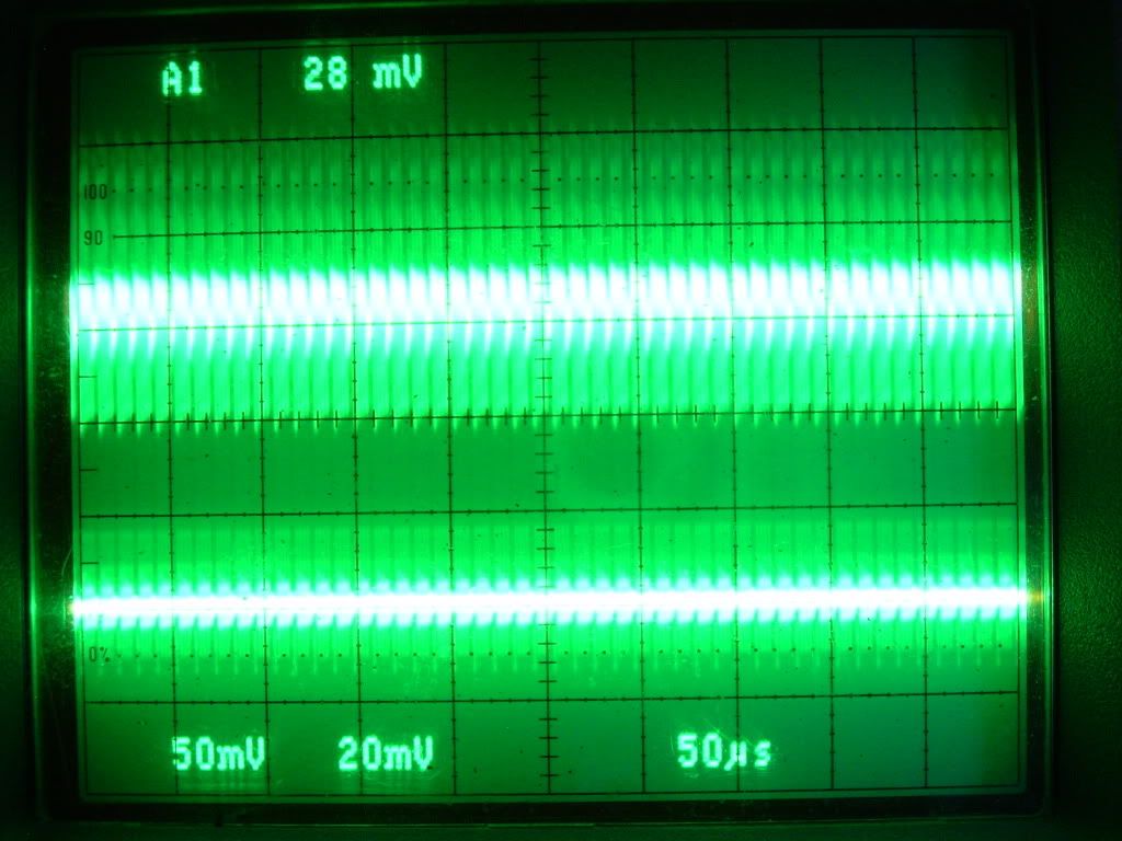
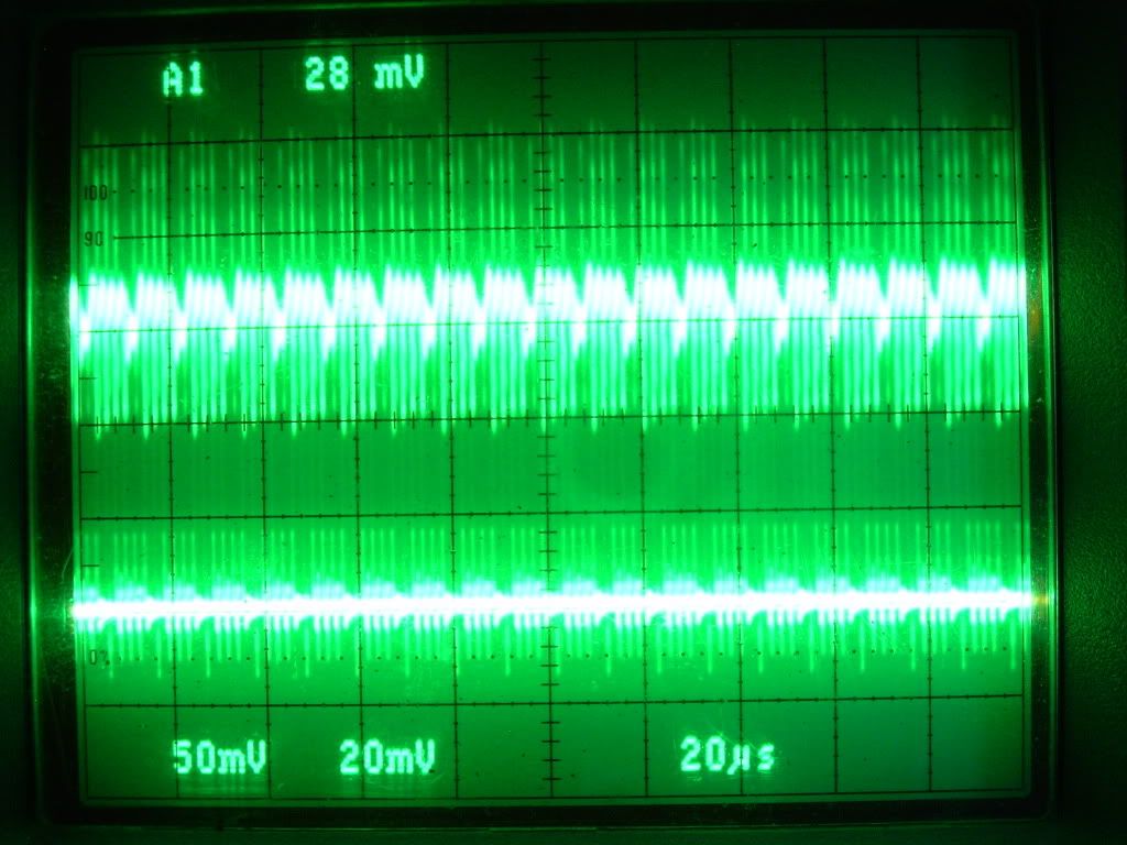
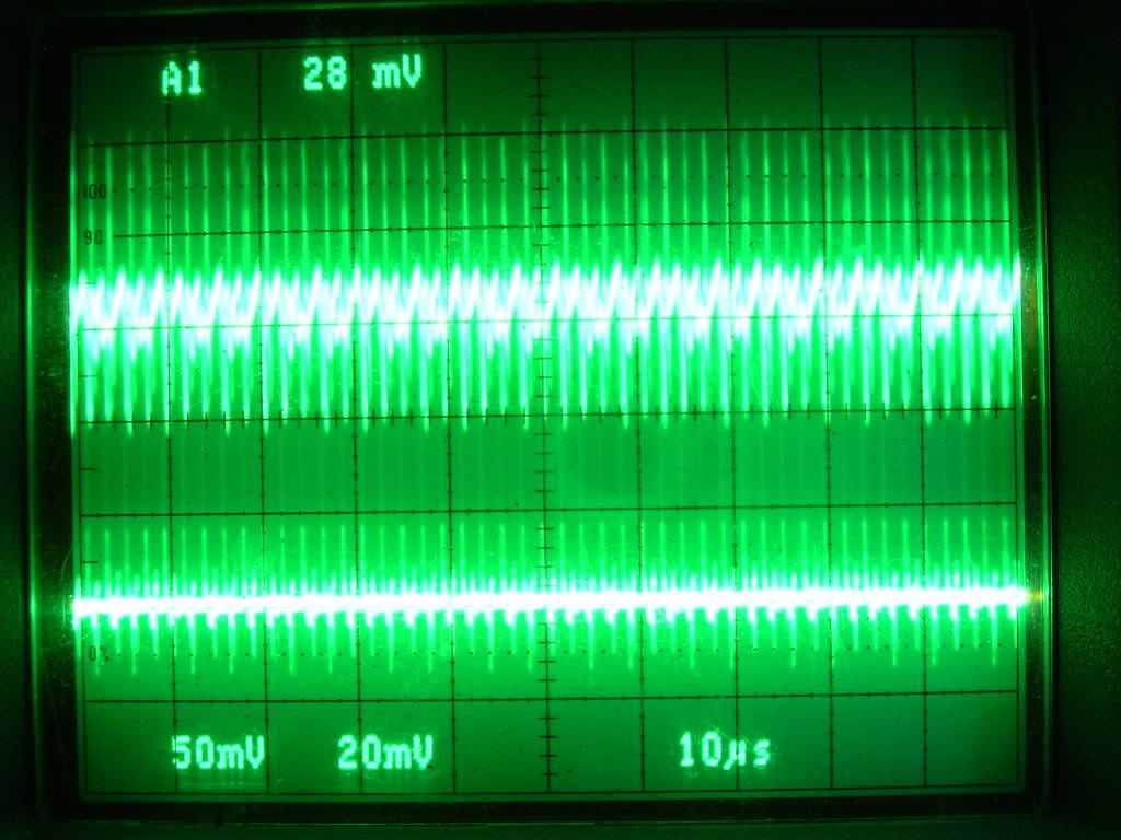
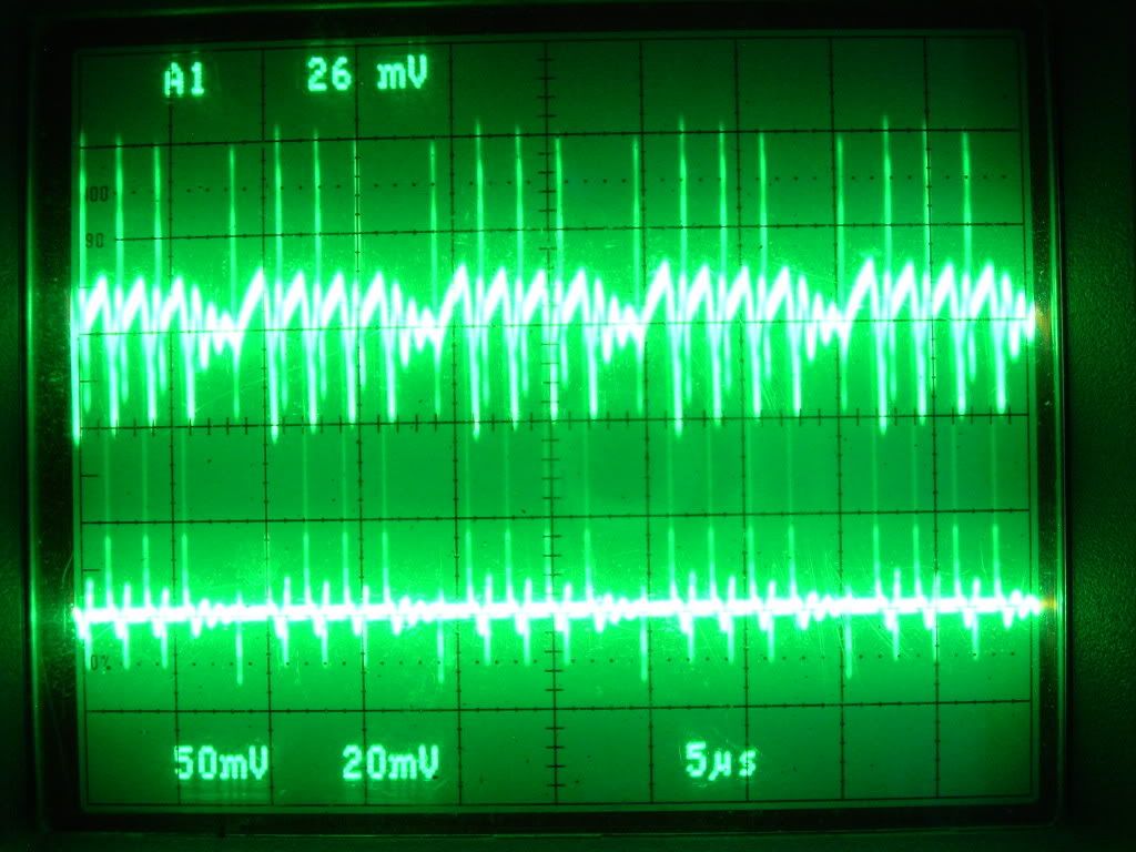
                              Well after watching my scope and DMM for hours now with the same results I am extremely pleased to show everyone the results from the last changes I made to the "Ainslie-Murakami Negative Dominant Waveform Generator" ....

                              1) Adding a insulator between the Mosfet and the Heat Sink eliminating the antenna effect


                              2) A new "Liquid" lead Acid battery
                              Exide Technologies Model # GT-H
                              TRACTOR
                              CUTTING EDGE
                              25 Reserve Capacity Minutes at 25 Amps
                              Cold Cranking Amps 235
                              12 Volt
                              Unit: each
                              Unit Weight: 15.0000 lbs
                              UPC Code: 017724265936

                              And the results are in ......

                              Starting voltage after purchase at store 2:30 pm PDT 12.67 volts, Start test after Mosfet Insulation between heat sink 7:30pm PDT 12.67 volts ........ Right Now 1:30 am PDT 12.69 volts after 6 HOURS ....... .02 volt increase above voltage at time of purchase ......


                              Glen
                              Open Source Experimentalist
                              Open Source Research and Development

                              Comment


                              • Hi Glen,

                                You did apply heat sink compound to both sides of the mica right? I find silicone zinc oxide works best for mica applications.

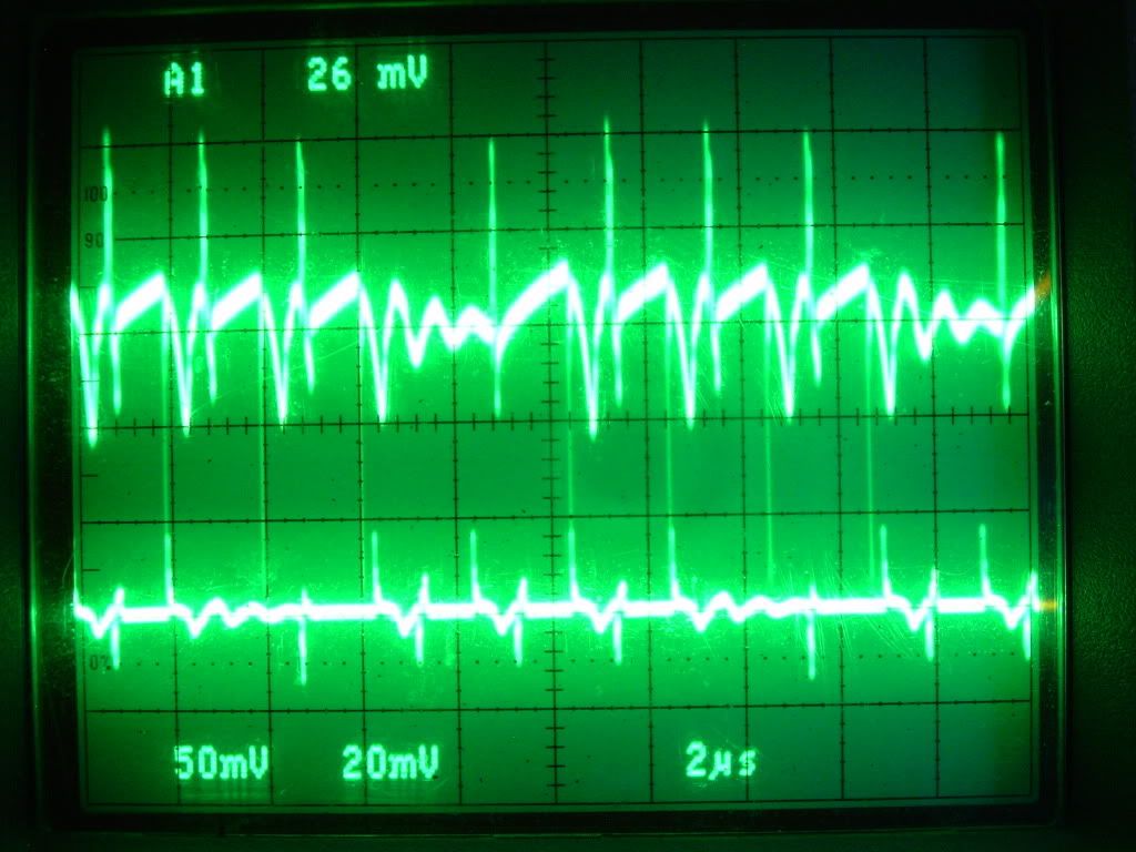
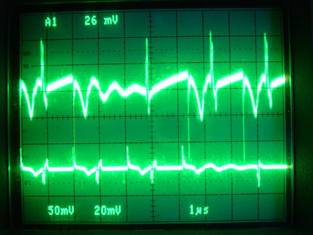
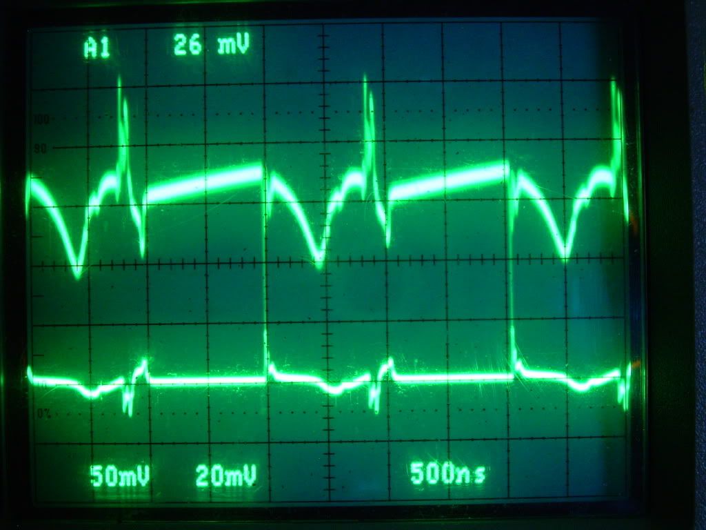
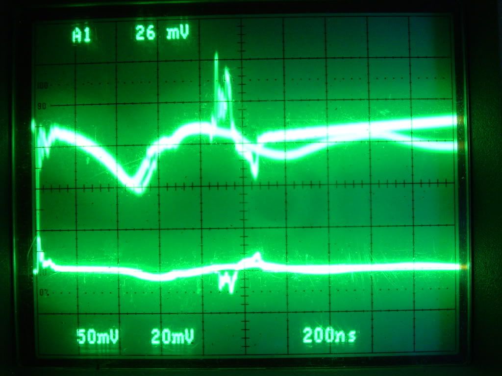
                                Interesting scope shots. Are your probes AC coupled there? I am interested in the missing null period in the 10µs shot that is evident in all the others. You can see a definite energy reduction for each pulse leading up to the small ring in the 5µs shot. Notice that at the end of the small ring (which is that null period) there is a smaller energy pulse, a slightly wider period and then the highest energy pulse. There is a reason that those 3 pulses decrease in amplitude and result in a rest period instead of retriggering. And the smaller energy spike at the end of the ring seems out of place. It would seem that the self triggering would like to do so during that rest period but something prevents it after which it succeeds at the diminished level just prior to a renewed cycle. So it looks like there should be 5 pulses there and their tops seem to map out a capacitive decay curve.

                                How wide was your timer pulse before aperiodic oscillation?

                                "Amy Pond, there is something you need to understand, and someday your life may depend on it: I am definitely a madman with a box." ~The Doctor

                                Comment

                                Working...
                                X