Announcement

Collapse
No announcement yet.

COP 17 Heater | Rosemary Ainslie

Collapse
This topic is closed.
X
This is a sticky topic.
X
X
 
  • Filter
  • Time
  • Show
Clear All
new posts

  • Hi,
    I did play again a bit around with it, and got a new old resistor, but it has thinner wire.
    So, i did connect a big Microwave Coil in front and back from the Resistor, and got some bigger Spikes.
    Also putting a Magnet inside or bring it closer can give strange Effects.
    But anyway, i tried the Quantum Timer and one from Aaron,
    and at a certain Point, i got more negative Spike then positive one, with both Timers, just at different Frequencys.
    That Resistor isnt that great, it has ~#28, and i think, thicker Wires are simple better.
    For adjusting, i did set the Duty cycle, there, where i still can supress it with the Gatepot(10K), and then adjusting the Gate again, and then the Frequency.
    But anyhow, i think, its hard to find without a Scope.

    And just dont connect something like a Coil or something inductive at Source Side of the Transistor, a Pot is ok, but else, it will kill the Diode. lol
    Theorizer are like High Voltage. A lot hot Air with no Power behind but they are the dead of applied Work and Ideas.

    Comment


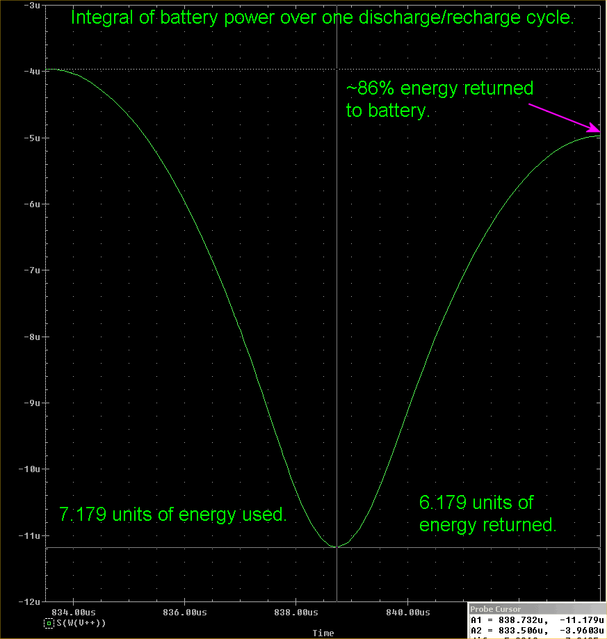
    • Correction to 95% Energy Return Figure

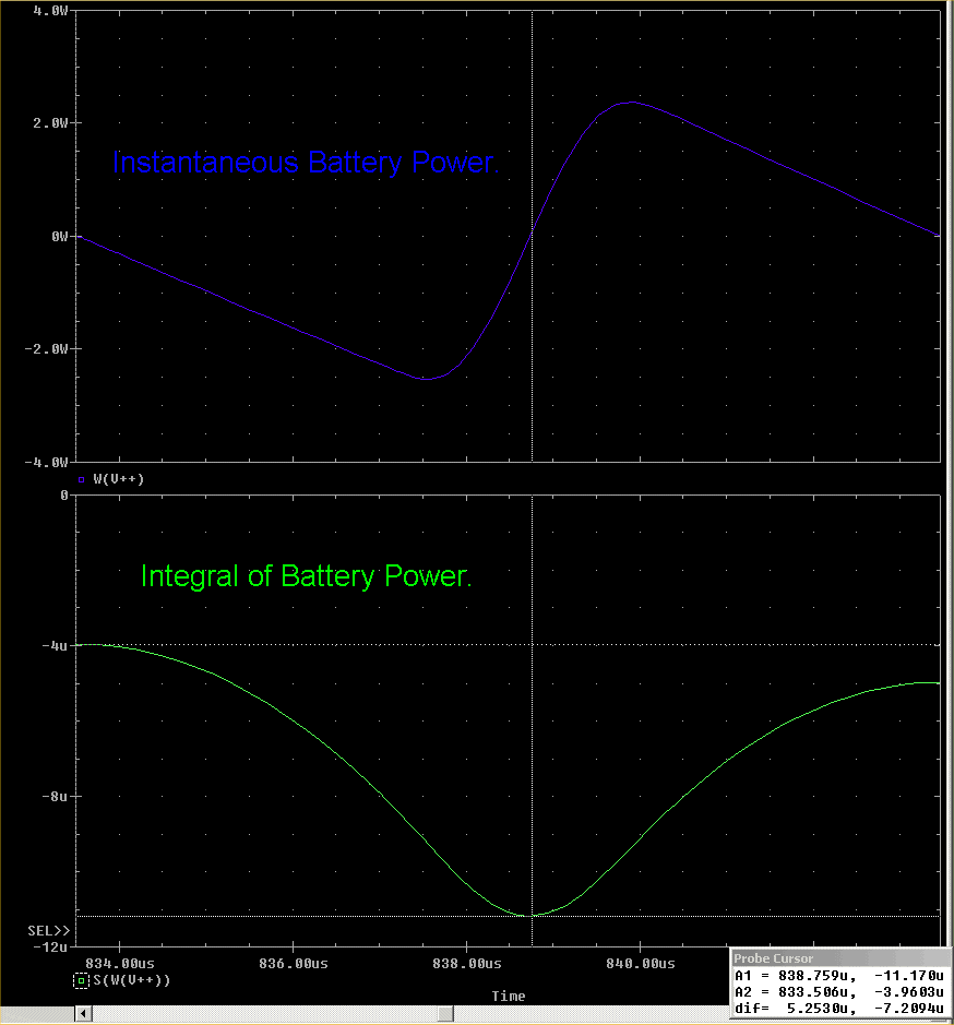
      Tried an integral in PSpice over the same battery discharge/recharge cycle shown in the previous scope shot where I estimated 95% energy return.

      If I did this correctly, the true figure is about 86% (6.179/7.179). Have a look and comment if it does not appear correct...MH?

      EDIT: Added shot of both instantaneous and integrated power together.

      .99


      Last edited by poynt99; 09-08-2009, 03:49 PM.

      Comment


      • Ainslie Circuit Non-Linear Tuning Zones 3 videos

        @all,

        Here are 3 vids that show what I mean by non-linear tuning zones that are similar to the negative regions in some transistors. I'm not sure if anyone else has noticed them but I've played with them for quite a while.

        Is it showing negative resistance in some areas? It sure seems like it. I'm able to get the voltage to increase while simultaneously the voltage drops. That pretty much by definition just like in some negative regions for transistor violates ohm's law and allows an increase in voltage with a decrease in current. There are quite a few areas of this with the 555 setup driving the IRFPG50.

        YouTube - Ainslie Non-Linear Tuning Zones 1

        YouTube - Ainslie Non-Linear Tuning Zones 2

        YouTube - Ainslie Non-Linear Tuning Zones 3

        What is the significance of all of this? You have to decide for yourself but just please be aware of the CONCEPT. You can find the areas where the amplitude is low in a zone or highest in a zone. Once finding one of those zones with one setting (on, off or gate), then move to the next dial and sweep it until you find more or go back if it is already the best, the next dial, etc... so between 3 dials, you can find some really incredible spreads between dc on the shunt and rms at the shunt.

        I show the waveform at the load but you can see they correlate.

        Anyway, if this helps anyone out at all, I have no idea. Just play with this concept if you feel inclined to.
        Sincerely,
        Aaron Murakami

        Books & Videos https://emediapress.com
        Conference http://energyscienceconference.com
        RPX & MWO http://vril.io

        Comment


        • Originally posted by Joit View Post
          Hi,
          ...
          That Resistor isnt that great, it has ~#28, and i think, thicker Wires are simple better.
          Hi Joit. I entirely agree here. But why should it work better. Is there a reason?

          Comment


          • Hi,
            Because of more Current and higher Spikes, what is flowing trough the resistive Wire, and cause more Heat?
            There is a Table about the Sizes below.
            I thought, maybe more Voltage would make more Heat too,
            but compared at the Ratio to the thinner Wire, seems there is both needed, Volt and current.
            Or a other Element, what heats up better?
            Theorizer are like High Voltage. A lot hot Air with no Power behind but they are the dead of applied Work and Ideas.

            Comment


            • @.99,

              The saturation is necessary for prolonging the ringing, but if the first ring clipping is less than the charging pulse then the resonant frequency of the inductor is too high for this particular test. I'm looking for a fully charged inductor which has a first clipping duration as long as the charge pulse.

              The scope shots I am looking for: B(-) Mosfet Drain as Reference, B(+) Mosfet Drain as reference. Desired traces for each, Voltage, Current, Power.


              Also, an integration of those for a 1 minute run. I doubt that it is long enough for any thermal modeling to become active, but it is a start to where I am going with this.

              Thanx again for your hard work on this.


              @Aaron,

              Sorry - no, not the MOSFET legs. The two your already did, B(-) to 555 - P1, B(-) to IRFPG50 - Source, and add a third from B(+) to Load resistor. Those would be the locations for the sensing resistors. We may need a fourth scope probe across the 555 power adj. pot and its value to calculate that power also. I'm looking to see if KCL is being violated in your working circuit. And I am looking to see which direction it is in if it is. Thanx. WRT negative resistance, I have studied what I can on that over the years, you may wish to look this over: Apparent Negative Electrical Resistance in Carbon Fiber composites Cheers.

              @Rosemary,

              The energy in that video is flowing through the people. It is a matter of which path is better suited for it to follow, the air, or the tube and the person. The plasma balls run on an AC adapter. Plugging it into a simple watt meter would show if the loading is passed on to the source. Remind me, perhaps I can do something with it after your cotton stringed magnets experiement (which I may need explained again later).

              Cheers,

              "Amy Pond, there is something you need to understand, and someday your life may depend on it: I am definitely a madman with a box." ~The Doctor

              Comment


              • Originally posted by Joit View Post
                Hi,
                Because of more Current and higher Spikes, what is flowing trough the resistive Wire, and cause more Heat?
                There is a Table about the Sizes below.
                I thought, maybe more Voltage would make more Heat too,
                but compared at the Ratio to the thinner Wire, seems there is both needed, Volt and current.
                Or a other Element, what heats up better?
                Hi, theres a neat wire calculator here at WireTronic Inc. Litz Wire Nichrome Magnet Wire Ultra fine Magnet Wire Tungsten that can use what ever type or size of wire you would like.


                PROGRAM LINK -
                Download Free Wire Info Software Now (Windows Ver. Only 528K)

                Glen
                Open Source Experimentalist
                Open Source Research and Development

                Comment


                • Originally posted by Harvey View Post
                  @.99,

                  The saturation is necessary for prolonging the ringing, but if the first ring clipping is less than the charging pulse then the resonant frequency of the inductor is too high for this particular test. I'm looking for a fully charged inductor which has a first clipping duration as long as the charge pulse.

                  The scope shots I am looking for: B(-) Mosfet Drain as Reference, B(+) Mosfet Drain as reference. Desired traces for each, Voltage, Current, Power.


                  Also, an integration of those for a 1 minute run. I doubt that it is long enough for any thermal modeling to become active, but it is a start to where I am going with this.

                  Thanx again for your hard work on this.
                  I can increase the inductance more to decrease the resonant frequency set up between the MOSFET and load, but it's a catch-22 situation. It will take more time to fully saturate the inductance which of course means lengthening the ON-time.

                  The only way I can see that might yield the equal ON-time and clipped-time scenario is to eliminate the 10 Ohm resistive part of the load leaving a pure inductance. If you see another way let me know, as what I've just suggested can not be realized in real life of course.

                  I'll try first increasing the pulse width to get to full saturation and see what happens to the clipped excursion.

                  .99

                  Comment


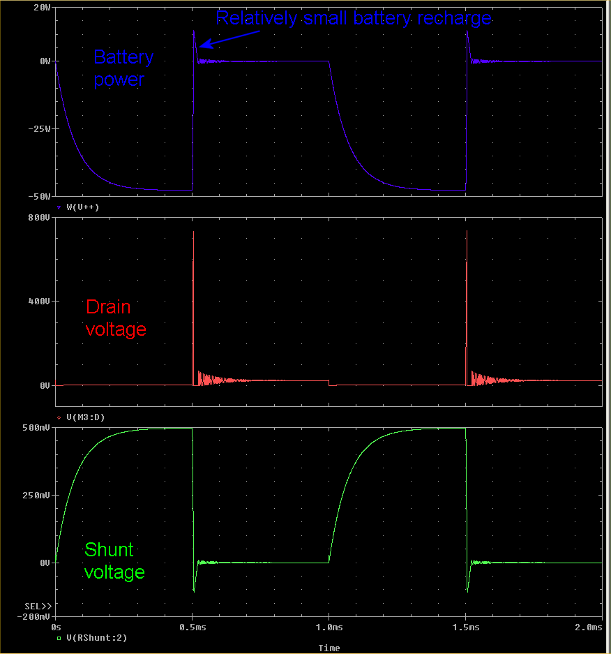
                  • No Go on the wider PW

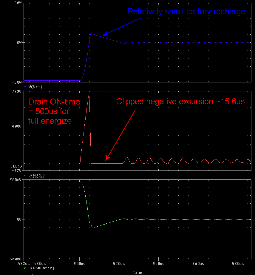
                    Found the full energizing time required for the 864uH inductance to be about 500us, so changed the PW to that and the period to 1ms.

                    As I suspected, this is going the opposite way if the goal is to equalize the ON-time and negative excursion clipping time. The latter result is only about 15.6us compared to the 500us Drain ON-time.

                    If we want to play in the reactive realm, we'll have to stay mostly in the reactive realm, and that means at the beginning of the energizing phase, otherwise the resistive part comes largely into play.

                    See plots:

                    .99


                    Comment


                    • Quantum circuit scope shots

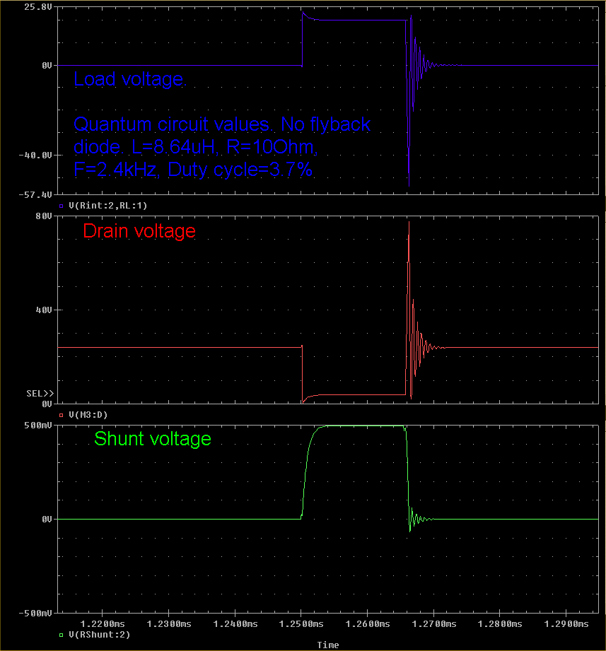
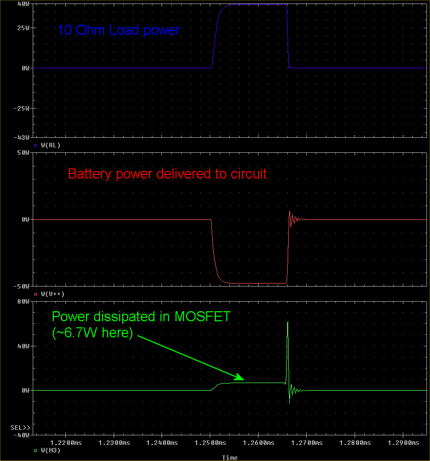
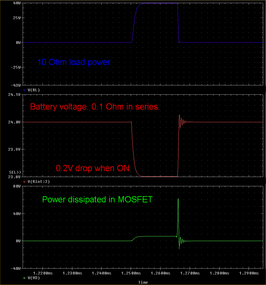
                      As per Rosemary's request, here are a number of circuit plots using original values and input. No flyback diode present. 555 circuit not used, just pulse input as per specified parameters: 2.4kHz, and 3.7% duty cycle.

                      See also posts #2527, and #2537 (454.5kHz input).

                      .99


                      Comment


                      • Poynt - many thanks for this. Much obliged. Can we have some synopsis on the numbers?

                        Comment


                        • Numbers

                          Rose,

                          Most of the numbers are there, but extracting them for you we have:

                          Load Voltage: +24V ~ -55V swing
                          Drain voltage: 0 ~ 80V swing
                          Shunt Voltage: 0.5Vp
                          Load Power: 40Wp
                          Battery Power: 49Wp
                          MOSFET Power: 6.7Wp and 60Wp during brief flyback
                          Battery Voltage: 24 nominal, 23.8V when switch ON

                          "p" signifies a peak value during the 15.416us ON time.

                          .99

                          Comment


                          • Thanks for the efforts here Poynt. Much obliged. There's some small fraction missing but I guess this efficiency is therefore at about 80%. Is that standard on a switching circuit?

                            Comment


                            • @Harvey

                              Originally posted by Harvey View Post
                              Sorry - no, not the MOSFET legs. The two your already did, B(-) to 555 - P1, B(-) to IRFPG50 - Source, and add a third from B(+) to Load resistor. Those would be the locations for the sensing resistors. We may need a fourth scope probe across the 555 power adj. pot and its value to calculate that power also. I'm looking to see if KCL is being violated in your working circuit. And I am looking to see which direction it is in if it is. Thanx. WRT negative resistance, I have studied what I can on that over the years, you may wish to look this over: Apparent Negative Electrical Resistance in Carbon Fiber composites Cheers.
                              I have 4 shunts now.

                              neg batt to shunt to mosfet source
                              neg batt to shunt to neg rail for 555
                              pos batt to shunt to load
                              pos batt to shunt to pot meter for 555 power control

                              all are 0.25 ohms

                              I have scope channel 1 & 2 common ground and probe across each shunt on negative side.

                              If I use a common ground for the positive side, it will simply show the battery voltage. If it needs to be common ground to have channel 3 & 4 that means I can't do the negative and positive ones at the same time.

                              Also, I think it is much simpler to use one shunt to show the draw on the neg and one on the positive.

                              Anyway, I could log the data for the neg side then after that is done, I can log the data on the positive side. Comments?
                              Sincerely,
                              Aaron Murakami

                              Books & Videos https://emediapress.com
                              Conference http://energyscienceconference.com
                              RPX & MWO http://vril.io

                              Comment


                              • Originally posted by witsend View Post
                                Thanks for the efforts here Poynt. Much obliged. There's some small fraction missing but I guess this efficiency is therefore at about 80%. Is that standard on a switching circuit?
                                Yes there is a small fraction of power dissipation missing from the 0.25 Ohm shunt, the 0.1 Ohm resistance in the battery, and a minute amount perhaps in the series 100 Ohm Gate resistor.

                                I excluded them because one, it's more work for me, and two, they were insignificant I thought, and one still gets the main picture I feel.

                                .99

                                Comment

                                Working...
                                X