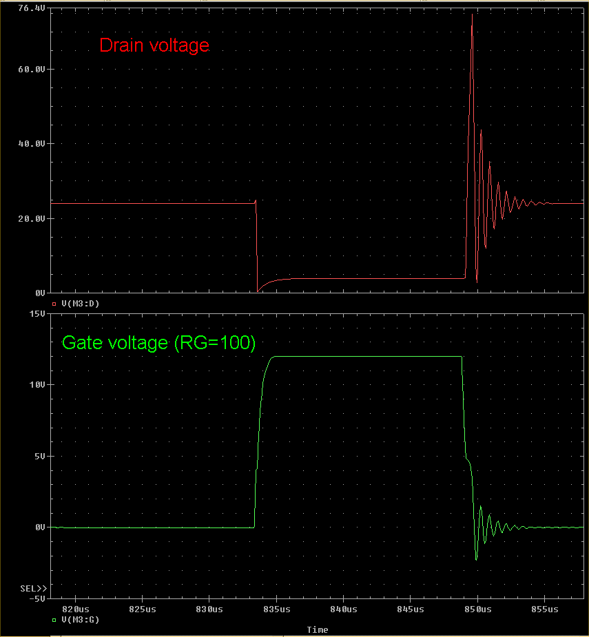
Rose, the first high voltage spike (after the MOSFET turns OFF) on the Drain is actually in the positive direction (relative to Ground), and it is this spike that poses the "stress" on the unprotected MOSFET. This is the danger MH has warned of and it is there, especially when fast switching speeds are attained.
If the MOSFET Gate is driven through a series resistance (such as how everyone on this experiment seems to be doing), then there will be feed-through of this spike from the Drain to Gate via the G-D capacitance. In all my tests I'm using a 100 Ohm resistance in the Gate and I see the biggest spike at the Gate pin is in the negative direction and it is about -2V.
Where are you viewing a Gate voltage wave form? I haven't yet posted one, have I?
.99


Comment