Announcement

Collapse
No announcement yet.

COP 17 Heater | Rosemary Ainslie

Collapse
This topic is closed.
X
This is a sticky topic.
X
X
 
  • Filter
  • Time
  • Show
Clear All
new posts

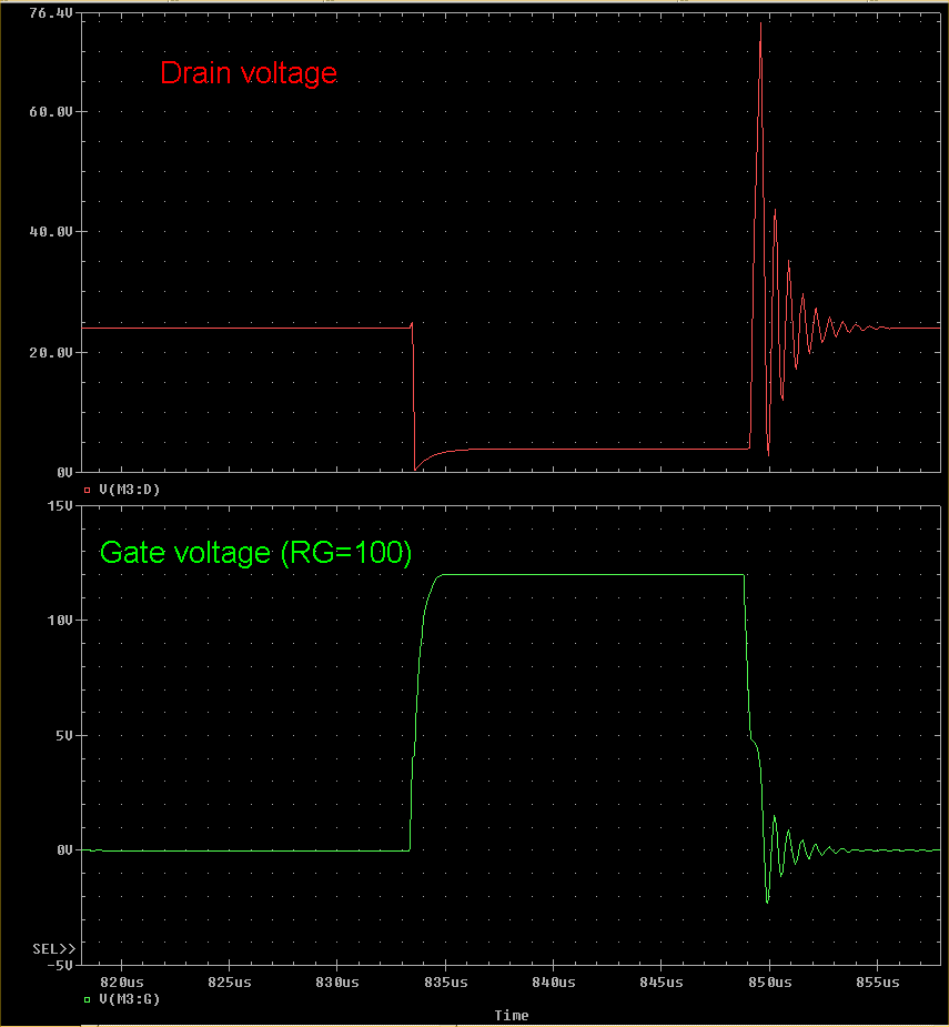
  • Rose, the first high voltage spike (after the MOSFET turns OFF) on the Drain is actually in the positive direction (relative to Ground), and it is this spike that poses the "stress" on the unprotected MOSFET. This is the danger MH has warned of and it is there, especially when fast switching speeds are attained.

    If the MOSFET Gate is driven through a series resistance (such as how everyone on this experiment seems to be doing), then there will be feed-through of this spike from the Drain to Gate via the G-D capacitance. In all my tests I'm using a 100 Ohm resistance in the Gate and I see the biggest spike at the Gate pin is in the negative direction and it is about -2V.

    Where are you viewing a Gate voltage wave form? I haven't yet posted one, have I?

    .99
    Comment


    • Some Wise Advice

      Some points from a knowledgeable friend whose expertise is in measuring micro-volt and micro-amp signals/noise:

      Could you kindly remind everyone that when 'scoping, all probe grounds should be attached to a single point ground, i.e., the bat neg. I see Aron believes being on the bat- side of the shunt is the same as being on the bat-. It is not, that point is one of his cliplead drops away from bat-. As the scope channels all share a common internal ground (except the little Flukes, which are isolated and intended for industrial AC power usage), connecting some scope probe grounds to the bat- and other probe grounds to a cliplead drop away from bat- means the scope lead grounds are carrying current (shorting out the cliplead Vdrop). This is a "ground loop" and can affect measurement accuracy (particularly at his millivolt levels).
      and
      I was wondering if his -34 millivolts across the shunt was just measurement error from all his clipleads. An RS cliplead is probably close to his shunt R, but with the addition of strays. Not using a single point ground under those conditions puts current on the probe shields. The degree of error would then depend on scope trace size, layout, reference tie point, probe shield R, etc. I have to measure noise at microvolt levels, no easy task!
      Courtesy "aethertech".

      Aaron et al, if you're reading this, hopefully this advice will be considered.

      .99
      Last edited by poynt99; 09-10-2009, 01:07 AM.

      Comment


      • Thanks so much poynt , Aaron Harvey. Time to get busy this weekend in the shop, will promise to sleep

        Comment


        • Poynt - I'm going to say this again and hopefully it wont need a repeat. If the voltage across the shunt were shown as +34 millivolts no-one would have questioned the value. It in fact shows a negative 34 millivolts. To compound the problem - if such it is - is the fact that the voltage waveform also appears to be greater below ground than above - just 'eye-balling' it as MH puts it. Then there is the voltage across the loads that are definitely readable - and there's heat or cooling all over the place.

          Notwithstanding your urgent protestations to the contrary - if there is, indeed, a negative voltage being measured - then it will always be discounted as 'noise' as that number will always be zero or close. A zero net voltage is, of necessity, rather small. I don't know how many ways to say this. But it's getting repetitive. If there was no evident 'shape' to the waveform - then I'd be inclined to believe that it was simply noise. The waveform definitely has shape.

          But thanks - yet again - for the input. I must admit I'd prefer an open discussion on the implications of this measurement based on the possibility that the measurement is correct. If this zero net loss evidence is simply discounted any time it manifests - then - quite frankly - any coefficiency of performance greater than 1 will also always be discounted. So any efforts expended in trying to prove the possibility will be obviated. Like I say mainstream are inclined to discount the evidence required for proof - using fair means or foul.

          Comment


          • Rose.

            First, this was some comments made to me in private. So I guess you are taking issue with him as well as me on this issue.

            Second, maybe you missed the essence of aethertech's message, and that is that even though there is a readable signal on the scope or meter, that does not mean for certain that this reading is correct, IF good wiring and grounding practices were not heeded. It is amazing for example, hold the leads of a meter set on DC volts in your hands, not even on the bare probe tips, but just in your hands, and you can see 100mV registered with ease on the display. In a sea of noise, 34mV, either positive OR negative may not be meaningful information, especially if one hasn't done their due diligence in eliminating all possible sources of error beforehand.

            I don't necessarily expect you to agree or understand where I'm coming from here but it is something to consider. Personally, I don't put too much faith in low mV readings no matter which direction they are coming in as unless the environment in which these readings are being taken is as electromagnetically pristine as possible.

            I don't think this issue is a done deal yet. I've got one or more videos coming up.

            .99

            Comment


            • Originally posted by poynt99 View Post
              Rose.

              I don't think this issue is a done deal yet. I've got one or more videos coming up.

              .99
              Can't wait. But I guess I know the general theme. Will you post on youtube?

              Comment


              • preposterous thinking

                Originally posted by witsend View Post
                If the voltage across the shunt were shown as +34 millivolts no-one would have questioned the value. It in fact shows a negative 34 millivolts. To compound the problem - if such it is - is the fact that the voltage waveform also appears to be greater below ground than above - just 'eye-balling' it as MH puts it. Then there is the voltage across the loads that are definitely readable - and there's heat or cooling all over the place.

                Notwithstanding your urgent protestations to the contrary - if there is, indeed, a negative voltage being measured - then it will always be discounted as 'noise' as that number will always be zero or close. A zero net voltage is, of necessity, rather small. I don't know how many ways to say this. But it's getting repetitive. If there was no evident 'shape' to the waveform - then I'd be inclined to believe that it was simply noise. The waveform definitely has shape.

                But thanks - yet again - for the input. I must admit I'd prefer an open discussion on the implications of this measurement based on the possibility that the measurement is correct. If this zero net loss evidence is simply discounted any time it manifests - then - quite frankly - any coefficiency of performance greater than 1 will also always be discounted. So any efforts expended in trying to prove the possibility will be obviated. Like I say mainstream are inclined to discount the evidence required for proof - using fair means or foul.
                Hi Rosemary,

                This response is for the first of the three paragraphs you posted above.

                EXACTLY!!!

                Whatever LOGIC, TECHNOLOGY, THEORY, MODEL, ETC... that was used to show the positive values of +34mv for example is the EXACT SAME LOGIC, TECHNOLOGY, THEORY, MODEL, ETC... that was used to show the NEGATIVE values of -34mv for example.

                If the negative values are claimed to be erroneous, then by default, the positive values must be erroneous. Allowing one to be accurate and denying the other is preposterous.

                On the second paragraph, it was clearly shown in my youtube video what is noise and what is a real signal on this circuit, my particular circuit, as measured by two different scopes simultaneously; A Tektronix TDS3054C and a Fluke 123 Scopemeter. Therefore, I think any claims of noise is preposterous.

                The last paragraph I totally agree with too. The conventional believers will forever be trying to maintain and sustain their current paradigm. At least, a majority of them will be. Who are the truly open minded ones out of the conventional believers? Time will tell I guess.
                Last edited by Aaron; 09-10-2009, 07:44 AM.
                Sincerely,
                Aaron Murakami

                Books & Videos https://emediapress.com
                Conference http://energyscienceconference.com
                RPX & MWO http://vril.io

                Comment


                • Try a little optimism

                  Originally posted by witsend View Post
                  Can't wait. But I guess I know the general theme. Will you post on youtube?
                  What theme Rose?

                  Be optimistic that I will be presenting data as it rolls off the equipment. What else can I do?

                  Yes, the vids will be posted up at Youtube. I'll of course advise the EF when I have one ready for viewing.

                  .99

                  Comment


                  • From "aethertech"

                    I am quite intrigued by Aron's -34mv measurement. I am hoping that number IS correct. Wouldn't that be something! Who needs "normal"...

                    One would think, however, that the suggestion to do whatever is possible to verify that the measured value is correct would, at least, be "acceptable". Whenever unexpected or unusual measurement results are obtained, it is only logical to investigate/eliminate all possible sources of measurement error or unintended current flow. Extending a scope probe ground so that it can be connected to the same point as the other scope grounds does not seem unreasonable nor difficult (although in the presence of RF/EMI, extending a ground lead can have consequences, better to move the setup a bit). If the measurement does not change, then possible ground loops via the probe shields have been eliminated. Continue down the list, eliminating each possible variable, and if the results stand, then the probability becomes higher that the number is correct. A next step might be to disconnect all but the shunt and flow a known and similar amount of isolated DC current between its free end and the bat+ to verify measurement accuracy at DC, and then inject a known AC signal to verify AC measurements. If those sources measure as expected, the probability of the minus 34mv across the shunt being correct continues to increase.

                    At microvolt levels, I have to be concerned with thermoelectric effects of dissimilar metals in probes and the measured circuit, attain thermal equilibrium, use Kelvin connections, Faraday cages, be aware of signal commons and ground paths, verify calibrations, its quite the exercise. Even then, often a statistical average is the best that can be achieved.

                    aethertech
                    I couldn't agree more.

                    .99

                    Comment


                    • "Frequency Counter"

                      Hi everyone,

                      I have found a fairly good method of fine tuning your "Ainslie-Murakami Negative Dominant Waveform Generator" and possibly the "Ainslie COP>17 Heater Circuit" replication circuit using a "Frequency Counter" at the battery (+) and (-) connections. In using these connection points with a scope of lower Mhz sampling rate small potentiometer adjustments during "aperiodic oscillation" are happening but cannot be seen, also any RF interfearence can also be a problem because if the "Heat Sink" shaped like a little antenna if not isolated from the "Mosfet" picks up signals that drastically changes the frequency of the replication.

                      The 10 ohm "load" resistor can also effect the replication as it appears small RF wave amounts are coming out from the resistor ends and can change the way the Mosfet operates and frequency of the replication if the ends are pointed towards the Mosfet

                      The best frequencies for operation is around 1150.00 Khz (1.15 Mhz) to 1250.00 Khz (1.25 Mhz) for the phenomenon Aaron is describing.

                      Hope this may help

                      Glen
                      Open Source Experimentalist
                      Open Source Research and Development

                      Comment


                      • Thanks Fuzzy. Sounds really good. How are those resistors coming on?

                        Comment


                        • Hi Poynt. Nice so see that little flicker of optimism?

                          And also nice to see the 'check list' needed for aethertech. I'm sure Aaron will do the necessary but right now he's knee deep in those wretched control tests. Still when they're done his test results will be quickly evaluated.

                          Comment


                          • bypassing body diode with better diodes

                            I started to play with different ways to bypass the internal body diode of the mosfet to see if I could take heat away from the mosfet by using a better diode. I was at 95% duty so of course it will warm up pretty good...but still only 1/2 of the temp of the load.

                            Well, I suppose that is only valid for that purpose if it is the diode that is showing the heat.

                            Anyway, what I found was that it didn't really drop the mosfet heat substantially. However, for example, with the modification and without - with I got a few degrees hotter for 1.3 watts LESS!

                            I have not tested this modification at the higher frequencies and lower duty cycles but it was unexpected that the difference would be that much.

                            I was doing one test at 95% duty cycle at about 4.77khz and the load was at about 50C above ambient for x watts. With bypassing the body diode with a better diode, I was at about 52C above ambient for 1.3 watts less. That is very substantial as in some of these tests with certain configurations, there could be around 10C above ambient for each 0.9 watts, roughly. If this translates to better running with the stock mosfet at unity conditions, then this mod just might be very significant.

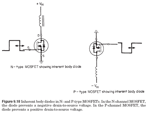
                            Anyway, I searched for some "body diode" references to see what the deal is and evidently, the body diodes of the mosfet are pretty junky, they are not fast and they just have terrible reverse ratings, etc...

                            Here is one reference to see:
                            Switching power supplies A to Z - Google Books

                            Page 197 there - the answer to question # 42, I didn't know that using diodes in parallel with the mosfet were a common practice - maybe not common but known.

                            Anyway, that spells out quite a bit in my opinion.

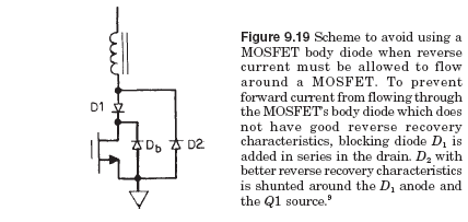
                            So, with a blocking diode opposed to the body diode and a parallel diode that goes to the blocking diode annode, the body diode is bypassed, load runs hotter for less input.

                            Glen, Harvey and others can probably fine tune the best diode setup for the IRFPG50. I'm using a 1n914 for the parallel didoe and a 6A100 for the blocking diode.

                            With a 1n914 blocking diode position, it gets super, super hot. The 6A100 is a robust but slow diode but it is handling the heat. I use a 1n914 from source to annode of blocking diode as the parallel diode and it works fine.

                            I found this diagram that shows it very simply:

                            Figure 9.19 happens to be EXACTLY what I tried and it worked.

                            On this page:
                            Chapter 9.2.12 - MOSFET Rain-To-Source (“Body&rdquo Diode On GlobalSpec

                            Chapter 9.2.12 MOSFET Rain-To-Source (“Body”) Diode
                            Inherently in solid-state structure of a MOSFET, a parasitic “body” diode
                            is located across the drain-source terminals as shown in Fig. 9.18.

                            The diode polarity is such as to prevent reverse voltage across the
                            MOSFET. The forward current handling capability and reverse voltage
                            rating of the diode are identical to those of the MOSFET itself. Its
                            reverse recovery time is faster than a conventional AC power rectifier
                            diode, but not as fast as discrete fast-recovery types. Manufacturers’
                            data sheets show the diode reverse recovery time for each specific
                            MOSFET.

                            The diode is of no importance for most switching supply topologies as
                            the drain to source is never subjected to a reverse voltage (drain


                            negative with respect to source for an N-type MOSFET, positive with
                            respect to source for a P-type MOSFET).

                            There are some exceptions—specifically, the half- or full-bridge topologies
                            of Figs. 3.1 and 3.3. But in these circuits there is almost always
                            a dead time between the time the diode conducts (when it is returning...

                            --------------

                            Anyway, any comments on the EXACT perfect diodes for this job?

                            I came across this schematic on this page:
                            Solid state tesla coil

                            Shows 1N5822 for blocking diode and MUR1660CT for the parallel diode.


                            Last edited by Aaron; 09-10-2009, 07:36 PM.
                            Sincerely,
                            Aaron Murakami

                            Books & Videos https://emediapress.com
                            Conference http://energyscienceconference.com
                            RPX & MWO http://vril.io

                            Comment


                            • frequency counter

                              Originally posted by FuzzyTomCat View Post
                              The best frequencies for operation is around 1150.00 Khz (1.15 Mhz) to 1250.00 Khz (1.25 Mhz) for the phenomenon Aaron is describing.
                              I might be able to borrow a frequency counter for this that would be useful especially after Tektronix is returned.
                              Sincerely,
                              Aaron Murakami

                              Books & Videos https://emediapress.com
                              Conference http://energyscienceconference.com
                              RPX & MWO http://vril.io

                              Comment


                              • bypass body diode

                                Page 62 and 63

                                The Control Techniques drives and ... - Google Books

                                Talks about body diode and shows modification as well.

                                Blocking diode should be LOW ON STATE VOLTAGE DIODE.

                                Parallel diode should be VERY FAST DIODE.
                                Sincerely,
                                Aaron Murakami

                                Books & Videos https://emediapress.com
                                Conference http://energyscienceconference.com
                                RPX & MWO http://vril.io

                                Comment

                                Working...
                                X