Announcement

Collapse
No announcement yet.

COP 17 Heater | Rosemary Ainslie

Collapse
This topic is closed.
X
This is a sticky topic.
X
X
 
  • Filter
  • Time
  • Show
Clear All
new posts

  • Originally posted by Michael John Nunnerley View Post
    Hi luc

    Assuming that the circuit is connected right, what are you using to switch the mosfet, is it your signal generator? if so can you tune it so as you are getting multiple harmonics in the phasing coil? if not it may be that the duty cycle is the problem. With my PWM I have variable duty cycle and I do not think at any time it is at 50%, much less, as in the off time there is set up a resonance between the power coil (transformer) and the phasing coil with the cap, as many sometimes as 20 of various amplitudes.

    If you are using a signal generator change it for a simple 555 like Rosemary's and play around with the duty. If you are using the MO coils, put a ferrite rod in the middle of the secoundary and a neon across the secoundary coil as a tuning aid. When you have the resonance point the neon will be very bright, it will measure well over 1000v, I have had near 1500v and you would think that the neon would explode.

    Hope tomorrow with luck to do that video with a borrowed camera which seems ok with the circuit.

    Mike
    Hi Michael,

    that is strange if you did not see the private video then someone else was able to access since it now says it has 4 views and I know for sure I only had 2 views which I did. I guess there is nothing really private

    Anyways, you're right I used my SG to switch the IRF640 Mosfet since I thought you said you had a 50% duty cycle. I'll try it with the 555 and Neon and play with duty cycles to see what I come up with.

    Luc

    Comment


    • Originally posted by Michael John Nunnerley View Post
      Hi Harvey and all

      How can we convert high voltage low current into a lower voltage higher current.

      I am able to run a 35v dc motor on the output that I am getting and have thought of using this to power a generator but it would be more practical if we had an electronic solution to this.

      A bank of batteries in series is a thought but that would increase the power in the circuit if all were used to the input. Or we could use just two as the input and recharge four which would be a better solution.

      As I am more of a hobbyist in electronics, I need to ask this question, high voltage put across a suitable resistance will drop the voltage in leu of increasing amperage, right or wrong?

      Mike
      Hi Mike.

      Resistance is a loss mechanism, it will drop the voltage and limit the current. In a truly efficient system, the resistance should only exist in the load where the work is performed.

      To transform power from a high voltage low current into a low voltage high current we typically use a transformer. This can be problematic when the signal being processed is a multi-frequency or polyphasic signal. One solution which I have alluded to is the extraction of the high voltage into the inner cavity of a metallic container. Maxwell has helped us to see that the inside can never be more than zero, therefore it will always accept more voltage pushing the outside of the container higher and higher. An MOV of sufficient rating attached to the outside of the container can have its discharge path through the primary of an HV transformer. The output of that transformer will be a lower voltage, higher current source. The higher the Q of the transformer the better.

      A well designed circuit of this type can apply resonance to the output stage which is excited in phase by the MOV discharge event. This way, the MOV may only fire once per second, but the secondary may resonate 60 times in between each excitation. As long as they are synchronous no appreciable energy will be lost in the transmission and transformation.

      This method allows us to couple several technologies including the capacitance of a Van de Graff system into an effective extractor for the complex energy produced in these circuits. The final stage then can be rectified and filtered and a portion returned to recharge the source.

      Maybe...

      "Amy Pond, there is something you need to understand, and someday your life may depend on it: I am definitely a madman with a box." ~The Doctor

      Comment


      • Originally posted by FuzzyTomCat View Post
        Hi Rosie,

        As you know with some other members ...... every time I do a test I leave the circuit running and draw down the battery's some prior to doing a re-charge for the next tests .... here is some data on Test #16 a battery draw down starting off at 3 hours "AFTER" the test was completed and went on to 13 hours "AFTER" the test was done .....

        Glen
        Looking at test 15 & 16, it seems to me and please correct me if I'm wrong:

        1. The bigger 76mm tube allows for a bigger spike. "more current into battery."
        Spike looks to be higher in potential and over larger area. Battery responds to this with lower voltage bump but higher spike area it seems. (current)

        2. Lower frequency, and therefore

        3. Lower mosfet heat dissapation.

        4. Same coil heating.


        David

        P.S. On a related note, how do alkaline batteries respond to being in the circuit?
        I'm assuming I'd want that on the 24V end and not the 12V part that is going to receive the spike.

        P.S.S. Mike, I shot you a PM. When you say Phasing transformer, do you mean a flyback trans? Because "phasing trans" refers to a process of find phase characteristcs between a primary and secondary, not the actual object per se
        Last edited by eternalightwithin; 12-15-2009, 07:06 PM.

        Comment


        • Originally posted by eternalightwithin View Post
          Looking at test 15 & 16, it seems to me and please correct me if I'm wrong:

          1. The bigger 76mm tube allows for a bigger spike. "more current into battery."
          Spike looks to be higher in potential and over larger area. Battery responds to this with lower voltage bump but higher spike area it seems. (current)

          2. Lower frequency, and therefore

          3. Lower mosfet heat dissapation.

          4. Same coil heating.


          David

          P.S. On a related note, how do alkaline batteries respond to being in the circuit?
          I'm assuming I'd want that on the 24V end and not the 12V part that is going to receive the spike.
          Hi David,

          Your correct on the spikes being larger for the Mosfet drain to the 24 volt battery bank using the 76mm prototype resistor, but until I do a "thermo profile" of the two other new prototype resistors similar to POST #2974 we wont know how much of a gain actually exists. I'm presently in the process of acquiring another variable power supply to accomplish this task.

          As for the alkaline batteries ...... I haven't tried those ....... the large spikes to the 24 volt "liquid" lead acid battery's suppling the return voltage I'm producing now and not blowing up the battery's is enough excitement for me right now.

          Best,
          Glen
          Open Source Experimentalist
          Open Source Research and Development

          Comment


          • So it's for the 24V side. Damn. I have 3 lead acid batts, 2 of which are suboptimal .... ok deader than a doornail. Guess I'll have to suck it up and buy a 24V lead acid batt and use the good 12V batt for the other end. I bought 2 lantern batts (alkaline) and was going to continue experimenting with that.

            Comment


            • Hi eternalightwithin

              Just a quick comment. It would be interesting to try the experiment on those tired batteries of yours. Fuzzy can probably comment better here - but there seems to be evidence that a flat battery bank somehow enables that oscillation so that it goes on and on and on.

              It may be worth trying this, even if you use a separate battery for the switch. Just a thought. I'd love to know the result here especially in the light of Fuzzy's findings.

              So glad to see you're still at it.

              Comment


              • Originally posted by witsend View Post
                Hi eternalightwithin

                Just a quick comment. It would be interesting to try the experiment on those tired batteries of yours. Fuzzy can probably comment better here - but there seems to be evidence that a flat battery bank somehow enables that oscillation so that it goes on and on and on.

                It may be worth trying this, even if you use a separate battery for the switch. Just a thought. I'd love to know the result here especially in the light of Fuzzy's findings.

                So glad to see you're still at it.

                Hi David,

                It is possible to run the RA COP>17 circuit from a set of 12 volt "liquid" lead acid battery's for the 24 volt battery bank to a very low voltage level ( approx 11 volts total ) and maintain this for some time with a reduced load resistor temperature, but only if you have the specific adjustments and harmonic to begin with. If you start from dead to low battery's, it would be very difficult to get into a adjusted circuit oscillation that would give any gains or extended running before the battery's go beyond a point of no return.

                Best,
                Glen
                Open Source Experimentalist
                Open Source Research and Development

                Comment


                • Off Topic, but quite possibly tapping into the same source as Rosemary's circuit:

                  Steorn

                  Cheers,

                  "Amy Pond, there is something you need to understand, and someday your life may depend on it: I am definitely a madman with a box." ~The Doctor

                  Comment


                  • @Harvey
                    Off Topic, but quite possibly tapping into the same source as Rosemary's circuit:

                    Steorn

                    Cheers,
                    I would have to say that it is a variant (I use this word lightly) of the principles pioneered by Tesla, Bedini, and Newman.
                    The Anslie circuit isn't anyway like the Orbo...the key to these pulsed magnet motors are the precise control over timing intervals with sharp gradients and charge manipulation (decoupling FEMF and BEMF...Collapsing inductors).

                    The Anslie is an RLC circuit with an internally defined frequency range (RLC determines most efficient freq.). Efficiency relies on energy lvl changes in the atomic structure of the resistors to release more or less heat, and the ability to maintain resonance within system while load characteristics change.

                    The Pulse motors are intermittent forced oscillations (slight resonant ringing in each pulse). Efficiency relies on sharp gradients (sharp on and off times), correct timing, core efficiencies, geometry, and optimal components.


                    IMHO

                    Comment


                    • Radiant Science - I realise you wrote this for Harvey - but I'd be very glad to hear more of your thoughts.

                      How do you account for the extra energy - or do you just see it as an increased efficiency and somehow allowable in terms of classical paradigms? - on both effects.

                      Comment


                      • @Witsend

                        I'm not getting into the pulsed motors here (rude to divert threads).
                        But, take a look here


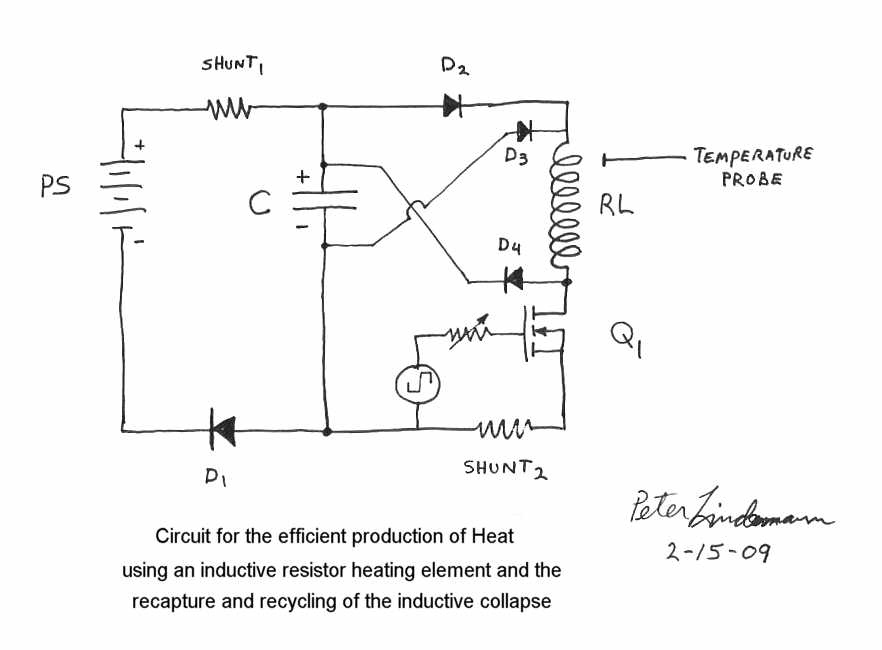
                        If you notice, D1 & D2 are facing the correct directions. D3 & D4 are reversed diodes.
                        So, every pulse creates not only magnetism and heat in the coils, but, as the pulse collapses the BEMF is re-routed back across the "filter capacitor" for an increase in voltage, if only for a moment.

                        Now, in resonance, this BEMF is continually impinged upon the input capacitor.
                        So, it is not wasting any of the electrical energy...unlike normal systems that ground out the BEMF spikes. Instead it is an additive effect. The normal energy supplied by the battery is being supplemented by the re-routed BEMF spikes.

                        In my opinion, the recycling BEMF increases efficiencies near perfect (only losses are in imperfections in components.)

                        That would ideally only account for a COP=1, or 100% efficiency. (which is amazing in itself)

                        But, I believe as Aaron has stated...further efficiencies lie in the choice of resistor material. Aaron suggests "German Silver" a copper/zinc alloy. Nichrome, and Stainless Steel are good choices for testing too.

                        I believe if you could make Bearden's "degenerate semiconductor" into a wire...that would give some amazing results.


                        You need to realize something common about many OU devices..."Resistance"
                        The "negative energy", "Orgone", "Pure Voltage/Poynting Flow"...whatever you wanna call it, increases power with higher resistance loads.

                        It's simple really, higher resistance loads mean, more electrons in the way. Basically, these uni-directional "shockwaves" don't give a hoot what's in the way...everything is gonna move. So...more objects banging together = more heat.

                        It's a matter of understanding the elements physical make-up, then picking the right one for the job.

                        Stan's stainless steel coil, Grey's graphite spark gap, Red hot electrodes in "Cold Fusion"....list goes on....you want events with highly non linear characteristics. Because, highly non linear events create Sharp Gradient shifts. It's these sharp gradient shifts that create anomalies. After all, the Atomic Bomb is triggered by a sharp gradient shift (High Explosive blast) to effectively short out atomic nuclei and disrupt their resonant circuit.
                        (I read somewhere about an explosive wire in an RLC circuit, that when exploded sent the RLC circuit so far out of equilibrium(sharp gradient) it released an immense EMP blast)

                        Things like gas discharges, avalanching energy cascades, spark gaps, mechanical switches, extreme gradient shifts, and high speed collisions (atomic scale) will prove to be most promising when trying to achieve COP>1

                        For an understanding how Atomic characteristics can release more energy, research Atomic Hydrogen, shifting energy levels, atomic resonance, electron spin, and spontaneous photon emission to name a few.


                        Hope I helped, good luck

                        Comment


                        • Dropping voltage

                          Originally posted by Michael John Nunnerley View Post
                          Hi Harvey and all

                          How can we convert high voltage low current into a lower voltage higher current.

                          I am able to run a 35v dc motor on the output that I am getting and have thought of using this to power a generator but it would be more practical if we had an electronic solution to this.

                          A bank of batteries in series is a thought but that would increase the power in the circuit if all were used to the input. Or we could use just two as the input and recharge four which would be a better solution.

                          As I am more of a hobbyist in electronics, I need to ask this question, high voltage put across a suitable resistance will drop the voltage in leu of increasing amperage, right or wrong?

                          Mike
                          You could use a capacitor - find one big enough so that the voltage coming in never actually fills the cap. Like trying to fill up a jug that has a huge hole in the bottom. So long as there is current extracted from the cap, the output voltage will stay lower than the input voltage.

                          Love and light
                          Atoms move for free. It's all about resonance and phase. Make the circuit open and build a generator.

                          Comment


                          • New video

                            Hi all

                            uploaded a new video, well part of the video, it is missing about 5min and I have now tried 4 times to do the rest, but, you tube will not have it, I am

                            The part that is missing is the voltages in the rest of the circuit and when I disconnect the return to the battery for a split secound and the flash and bang due to the rapid high voltage that forms in the caps, discharging into the battery.

                            I now allways have the return connected before switching on. I have blown a 235v 25w bulb on the return

                            Maybe you tube thinks the spark and bang is a type of bomb and so will not publish, very wierd.

                            I hope Luc has now got his working, I posted the incorrect values of c2 and c3 they should be 0.1mf not 1mf, sorry about that

                            MikeYouTube - web cam video of steap and the different voltages in the circuit

                            Comment


                            • possible radiation burn

                              Hi all again

                              forgot to mention something that has happened to me and as of yet I do not know if it has a relation or not with the experiments that I am doing.

                              Here is a photo of my arm that I have just taken.

                              I was at my doctors this morning and as she went to touch my arm there was a load bang and a 1cm spark from my arm to her finger, to say the least she was shocked, pun intended

                              Well we will see what they find of this and I will keep you posted.


                              Mike
                              Attached Files

                              Comment


                              • Caution - Handle With Care

                                Originally posted by Michael John Nunnerley View Post
                                Hi all again

                                forgot to mention something that has happened to me and as of yet I do not know if it has a relation or not with the experiments that I am doing.

                                Here is a photo of my arm that I have just taken.

                                I was at my doctors this morning and as she went to touch my arm there was a load bang and a 1cm spark from my arm to her finger, to say the least she was shocked, pun intended

                                Well we will see what they find of this and I will keep you posted.


                                Mike
                                Hello Mike. I've heard people being described as a 'live wire'. Never realised it was literal. Either that or you're really, REALLY attracted to your doctor? LOL . The analogies go on and on. Burned out, burnt by love, burnt by life's experiences, the 'spark' of interest. Endless really. I have a sort of 'sparky' love hate relationship with my keyboard - that bites me every now and again. I've learned wear rubber soled shoes before I get too busy here. But I have never heard of static being responsible for third degree burns. THAT IS JUST SO STRANGE. I think it's highly probable that you've become a kind human capacitor. Golly. In which case you can be accurately descibed as fully charged and live. I think you need to carry a written warning around your neck. LIVE - HANDLE AT YOUR OWN RISK. or just print a hazard warning on your shirt. It would help. Golly.

                                Your test results look amazing but I'm a plodder here Mike. Be very grateful for a schematic or a link to one - if you've got the time.


                                BTW Many, many thanks for the video. Interesting that youtube's doing editing there. I also had endless difficulty with the upload of a proton diagram - eventually cracked it by keeping the video down to about 40 seconds flat - and it then 'took'.
                                Last edited by witsend; 12-17-2009, 08:26 PM.

                                Comment

                                Working...
                                X