-
If you want to Change the world
BE that change !! -
Hi LucOriginally posted by gotoluc View Post
Yes, I had read Poynt99's document thoroughly before I posted the reference to it. I concur with his conclusions.
HoppyComment
-
Aaron,Originally posted by Aaron View Post
IF we can bend the "rules" regarding the accepted behaviour of electron flow and all associated (and possibly hidden) fields, then as far as I know you will not find the "method" or expos� in any classical text book.
.99Last edited by poynt99; 07-14-2009, 06:23 PM.Comment
-
Gotoluc - this is for you to think about.
The principle is this. On our experiment we generate counter electromotive force - not at a coil, as that would complicate the measurement protocol - but on an inductive load resistor. I believe they're referred to as 'curly wounds'. This still gives a kick - not as extreme as your coil - but enough for these purposes. This 'kick' is taken straight through the flyback to the postive terminal of the battery. We then see this. The battery is now able to recharge. And it is effectively being recharged from the very energy that it first discharged.
This, in itself is problematic. We are now saying, as Dr Stiffler pointed out, that we've withdrawn $2.00 from the bank - spent $2.00 and - from somewhere out of the ether - then redeposited something in excess of $1.00 back to the bank. That dollar - or that something more than a dollar? Where did it come from? This is the problem that classicists wrestle with. With good reason.
So. When we use a battery - in line with all good and classical measurements we can concede that the battery only delivers energy during the 'on' period of the switching cycle. We don't have to go into too much detail about the 'inductive component' as the inductive componenet here is in the resistor itself. Whatever it measures as 'heat' WILL also reflect the energy that was delivered.
The question then is how to compute the energy that was first delivered. Well there's no coil. So, presumably if we use a 'shunt' on the negative rail on the supply - then we can measure the voltage on that supply. We know that what the battery delivers can only relate to the ON period of the switch as this is the only time that the battery can, in fact discharge any energy. So that part is relatively easy. We take the vbatt divided by the Ohm's value of the shunt to compute current - and then multiply the current by the battery voltage to compute wattage. This is correct and strictly conforms to good classical measurement protocol. Whatever that number it precisely represents the wattage delivered by the battery.
Then comes the tricky part. The duty cycle changes. The battery is, in effect, no longer able to deliver any current. The fields on the resistor collapse to zero. And the strength of that collapse relates to the applied energy from the On cycle. Energy is energy. What comes in must go out. What gets kicked must be moved. And when magnetic fields collapse, all they are doing is changing in time. Magnetic fields changing in time induce an electric field. But the strength of those changing magnetic fields from some voltage to zero - also needs to discharge. There is only a very short period during which it can discharge being moments between the 'on' and the 'off' time of the switch. It takes full advantage of that 'moment' and developes a spike to carry the full force of the energy applied in the On time and kicks it back in nano seconds as a 'spike' that is always evident 'beween' the on and off period. That's the counter electromotive force.
But that energy is evidently also measurable on the shunt. And where does it go? It goes first through the battery, thereby recharging it - and then to the load thereby heating it up. So. We're back to that problem. How can we have found something more than $1.00 when we've already spent $2.00 to give anything back to the bank.
And yet. The paradox. Our measurement of that delivery of energy is determined by classical measurements protocol. Not by me.
I think you'll have picked up the significance as it relates to your utility supplier (edit) and to your test. But I'll get back to it.Last edited by witsend; 07-14-2009, 07:46 PM.Comment
-
Rosemary,Originally posted by witsend View Post
I am working at the moment so will try to respond later on today/tonight.
.99Comment
-
Back again
Hi Rose and all, I'm back again after not being able to access the forum here in Spain.Originally posted by RAMSET View Post
Ramset it is funny you have posted a link to this on Don Smith, this is one of my lines of investigation and part of my magnetic flux manipulation thread.
To keep things on track here, I think there is a link with Roses circuit in a round about way but at the moment I do not think it is apropriate in this thread, may be farther down the line, my opinion, but a fascinating topic
Mike
Comment
-
An electronic circuit to free energy
Hi Rosemary,
I hope this will help you, forum members and guests ..... It was one of those web sites referenced in a post that ended up in French and I just scanned over for interesting photos, images, drawings and saw the schematic and scope shots it looked real similar to what is going on. I'm glad you and others liked it great find from "NerzhDishual" a OU member .... I'll PM him over there and see If he wants to partake.
Best Wishes
Glen

------------------------------------------------------------------------
An electronic circuit to free energy
An electronic circuit to free energy
Quanthomme thank Zoltan Szili
we have entrusted the distribution of his work.
For all correspondence here is the email address Zoltazn Jean Szili
p_baril@sympatico.ca
Introduction
"By publishing this very simple circuit, I would give fans the opportunity to prove that the extraction of electrical power vacuum exists.
The purpose of my letter is to inform my work and help develop quantum generators for use by people and industries.
I decided to make public a first circuit, and fans will be able to test it. "
Presentation of the author
"My name is John ZS All my life I worked in scientific research. For seven years I am retired.
Thirteen years I lived in France. Five years in Lyon and Paris to eight years. In Paris, I worked at the University of Orsay in Physics of Plasmas. I was born in Hungary. I emigrated to Canada (Quebec) in 1969 and I found work at the Institut de Recherche d'Hydro Quebec in the field of scientific research. I stayed twenty-eight years until I retire.
One day at the restaurant of the institute, I sat at a table in front of two engineers and their invited experts processors. I listened to the conversation, and engineers have told their guest, they could calculate the parameters of transformers with an accuracy of 0.1%, but they are 2% of power still in too.
This surplus of power remains inexplicable while taking account of ohmic losses and so on. I left the restaurant thinking that this 2% of excess power could come from an unknown source.
A few years later I became aware of the theory of Zero Point Energy. I assumed that there should be a way to extract a part of this phenomenal energy. Since my retirement, I work hard to find circuits that could extract energy from the zero point. Quickly, I left out the laboratory work for the computer simulation, in order to expedite my work. I have tried thousands of channels before finding one and then several of these circuits that say in English "overunity".
Method of work
"When we explore an unknown field, one must use trial and error empirical. Gradually, we learn about this new unknown world of science and use this knowledge to find circuits more efficient.
Currently, I know quite well how to extract the ZPE. The power of my circuits ranges from a few milliwatts to more than one hundred kilowatts. These circuits must be powered to operate, but the output circuits, gains power (COP = energy output / energy input) may be very high. The gain or COP may be 2, 10, 100, 1000 and beyond.
In these simulations, I always used electronic components existing in the trade. This may facilitate the realization of these circuits in the laboratory. This work remains to be done.
First, this circuit has been developed on a computer simulation. This allows for the simulation, the Jiles-Atherton model of electromagnetism. This model was designed to meet the reality test and not the law of conservation of energy. I can not give guarantees regarding the functioning of this circuit, but until proven otherwise, have confidence in the simulation. This program is used across the world in electronic and physical laboratories. It is very close to reality, although in experimental 99.999% of 100 cases energy is conserved. "
The mechanism of extraction
"There are special conditions for there to be extracting energy from quantum vacuum fluctuations. The mechanism of extraction, in my opinion, is based on ferromagnetic resonance. The free electrons exchange energy with electrons virtual vacuum. Normally the exchange is completely symmetrical. Outcome: No energy extraction. In addition, electrons are fermions, and quantum mechanics, two electrons can not be the same. The result is a dispersion very large in the frequency of ferromagnetic resonance, might be called semi-collective. This resonance is between a few hundred MHz and several GHz. Nevertheless, the circuits operate at a frequency less than one MHz. As against the circuit must be built as a circuit operating at least 25 MHz. Avoid loops, using more appropriate component. In these circuits, you must use special methods to make the asymmetric exchange of energy. In this case only, there will extract energy.
In publishing this first tour, my goal is to stimulate research ZPE. I think especially for amateurs.
A new about my research: I think I have found a physical law, connecting the electric current in a coil (as used in the circuit is sent) and the inductance of the coil. This relationship seems to inductor current and fundamental in the extraction of electrical power. This relationship is reciprocal. A variation of current varies the inductance and inductance variation varies the current.
When electric current increases, it decreases the inductor, and a decrease in the inductance increases the current ... and so on. It is the effect of avalanche. The decrease of inductance has a certain limit determined by the electronic circuit. After stopping the avalanche, the process is reversed. The inductance increases and this lowers the power ... and so on. This return takes less time because there was no extraction of electric power vacuum during the return. Normally, because of electrical losses, the Avalanche will not begin without stimulation (eg a pulse above a certain value). The physical form of this relationship is as follows:
I (L1) = (K1 / L (L1)) - or I K2 (L1) is the current flowing through the coil and L (L1) is the inductance of the coil. K1 and K2 are two constants (unchanging) depending components of the circuit.
By adjusting the constants K1 and K2, the curves of current and inductance are virtually identical. For other circuits, the formula could change, but what is important is that the current relationship and the inverse of the inductance should remain valid. "
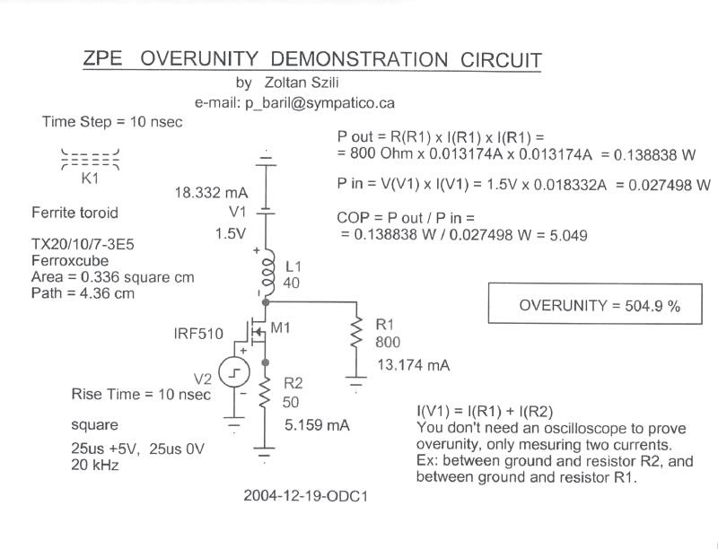
The electronic circuit free energy
Mr Zoltan Szili
"This circuit is very simple in appearance, but to successfully make it work, then you need to take drastic precautions. True, it operates at a relatively low frequency of 20 kHz. As against, the signal generator pulse must be a square, positive, with a rise time of 10 nanoseconds from 0 volts to +5 volts.
The simulation shows very clearly that if the rise time of the square is longer than 10 nanoseconds, the extraction decreases very quickly and completely canceled between 50 and 100 nanoseconds.
The simulation also shows that a parasitic capacitance at the point of connection of the transistor (M1), the inductor (L1) and output resistance (R1) with a value of 100 picofarads to ground, completely destroyed the extraction (capacity of 100 picofarads may be the ability of an oscilloscope probe).
The parasitic inductances can also prevent the extraction, if it exceeds 10 micro Henry.
In assembling the circuit, we must minimize the loops, as if the circuit were fonctio.nner to 25 Mhz
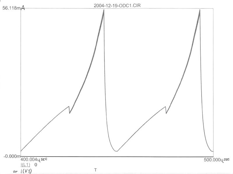
In fact, the element is the extraction of the ferrite toroid inductor (L1). "
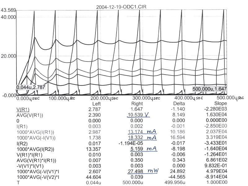
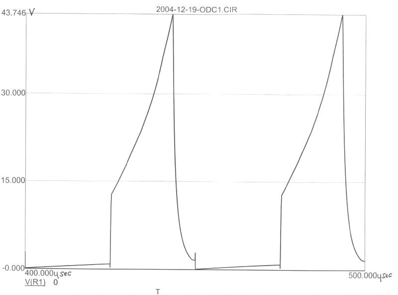
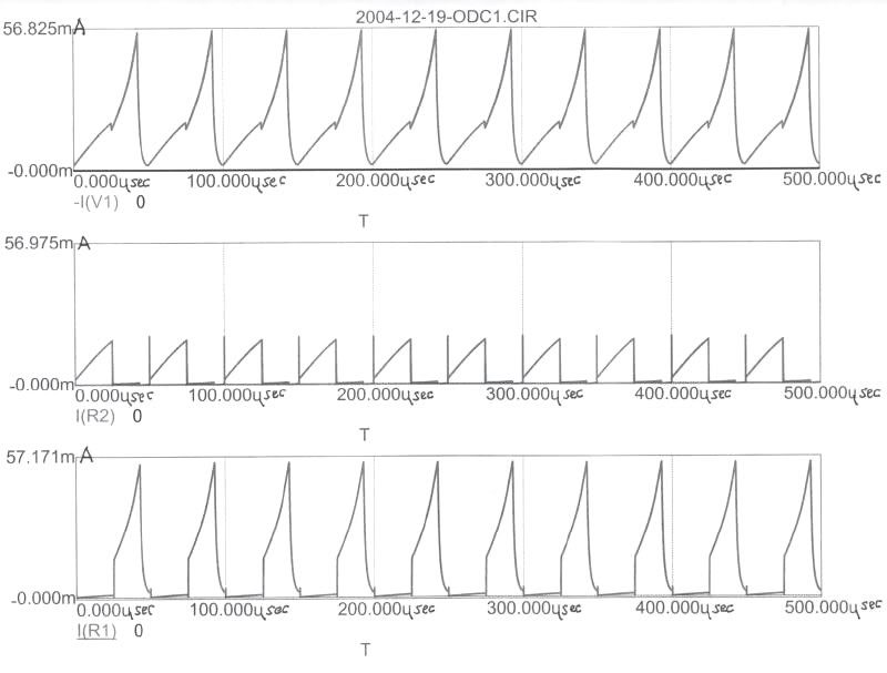
Schematic and measures
Not need an oscilloscope to demonstrate on the unit: it is enough to measure currents ex 2: between the earth and the resistance R2, and between the land and the resistance R1 "
-1 --
-2 --
-3 --
 Open Source Experimentalist
Open Source Research and DevelopmentComment
-
@witsend.
I dont know, if Tinselkoala did modify his timer Circuit, that he dont get the same Result.
My Scopeshot shows the same, as his last 'Way it is"
My Offset line is also the the low long bright Line from upper Channel.
The On Time shows up as the Peak.
Just the different, he use his Functiongenerator and need a Dutycycle of 96%, to get the Mosfet for ~3% ON.
With the Timer Circuit from the Quantum Article it does the same at the Mosfet, it sets the Mosfet ~3% to on.
Anyhow it sounds like, there is a Missunderstandig where the Duty cycle should be.
Maybe someone did read some Posts to fast? But i think, we can agree, that the 3% Cycle should be at the Mosfet ON time.
And may we should look different at the Puls from the Timer to the Gate, not as a rising Voltage,
more like a Unit of Energy, what saturate the Gate at a certain Point.
At last, his last Shot from the Scope and my Shots are identical.
So, his Statement, that the Timer Circuit dont works, still cant been right.
I am still waiting for it, that he do rebuild it with the right Parts, and it works, as he showed in his last Shot.
OR he goes finally into the Kitchen and bakes a Cake for us.
Maybe he did connect it different. I did it like
Plus - 10W Bulb - 2. Probe - Drain - Source - Minus
|-same Plus -> Diode - Timer - Pin3 - 1.Probe - Potentiometer - Gate
And from Scope Ground to Ground.
@Poynt99
Anyhow i dont get your Point, can you speak free please, at what you are thinking about, what the output from the Timer do/should cause?Theorizer are like High Voltage. A lot hot Air with no Power behind but they are the dead of applied Work and Ideas.Comment
-
TK is precisely correct with his demonstration, as he has been throughout.Originally posted by witsend
The problem that seems to be occurring here is folks are associating "voltage" with "ON", and "no voltage" with "OFF".
We are dealing with a simple switch here, and this is pretty much how the MOSFET should be viewed...as a simple single-pole, single-throw switch.
Now the question I will ask is this: What is the voltage across the two terminals of an ideal switch when it is turned "ON" (i.e. when the switch contacts are closed)?
It is zero volts correct?
What is the current through this same switch when it is turned "ON"?
The MOSFET acts exactly the same as this switch. So, when the MOSFET is "ON", there is zero volts across the MOSFET D-S leads, and since the S is connected to ground, we should measure almost 0V at the D lead when the MOSFET is "ON". This is also the state which will allow current through the load.
So, monitoring the voltage is confusing folks here. If the current was being monitored (i.e. place a bulb as the load), then it would become clear what is going on.
.99Comment
-
Originally posted by poynt99 View Post
Umm, can you repeat it at the case, you did write once a ON instead a OFF to often?Theorizer are like High Voltage. A lot hot Air with no Power behind but they are the dead of applied Work and Ideas.Comment
-
Rosemary,Originally posted by witsend View Post
Poynt99 has explained in detail EE terms how power is calculated and shared in the circuit. He has not attempted to calculate the effect of the flyback energy on the battery itself. I agree that the sum of energy delivered to the circuit by the battery is the difference between the two cycles. The problem is working out exactly what effect the flyback has had on the capacity of the battery. The stored capacity in ampere hours is very difficult to measure with a good degree of accuracy, even using battery capacity meters (BCM's). If this were possible, we would have a viable method of calculating the true COP of the system under test by taking a capacity measurement before and after the system test run. However, A BCM should be capable of providing a reliable indication of whether or not a given battery has gained or lost capacity over a given period of time and this will at least show if a system is operating at unity or better.
HoppyComment
-
Ramset - the video link was so interesting. It's amazing to think that here we are battling to get a really, really small effect accepted, and there's Don Smith selling ZPE to the arAabs, Chinese and just about everybody. We're already obsolete and not even our work is accepted by mainstream.
Brings to mind the Wright brothers flying over the the universities where the students are being taught that flight is impossible.
We're living in exciting times folks.Comment
-
Oh Men, i think his biggest Enemy is his own Ego.
Seems he want to have a Battle about, Who is right and Who is Wrong, no matter, from the Results of it.
Well, a Mosfet is not really total off, that why you can use it for a AC Circuit too. But it opens still only in one Direction with a Pulse.Theorizer are like High Voltage. A lot hot Air with no Power behind but they are the dead of applied Work and Ideas.Comment
-
FuzzyTomCat - you've done it again - pulled the cat out the bag. I've just seen the post. MANY MANY THANKS.
Can you now really perform a miracle and see if you can reach the guy and see if he'll talk to us. I've been trying to email him and nothing. He's got to be an asset. He's looking for us amateurs to test the theory. And I'm dying to talk theory.
I'd be so grateful if you could, perhaps try.
Thanks Glen - very much
Rosemary
EDIT - and everybody - PLEASE READ THAT PAPER. IT'S HUGELY SIGNIFICANT.Last edited by witsend; 07-14-2009, 07:39 PM.Comment
-
Don Smith
Rosemary I had to share that with you
I just got that today from user bolt at OU
should be required viewing for EVERY ONE
Seems like he was in the room during the event
Don Smith Free Energy - Video
ChetIf you want to Change the world
BE that change !!Comment
 Tweet
Tweet
Comment