Announcement

Collapse
No announcement yet.

COP 17 Heater | Rosemary Ainslie | Part 2

Collapse
This topic is closed.
X
This is a sticky topic.
X
X
 
  • Filter
  • Time
  • Show
Clear All
new posts

  • Originally posted by gadh View Post
    Hi Glen. i'm now trying to build the load resistor by the specs you gave, and i encountered some problems/questions:
    1. the tube material - how much heat (temperature , celsius) must it bear ? i need to know which material i can use to build the resistor.
    Hi Gad, I noticed your question since yesterday. I'll try and answer as I think Glen is away. If you use any ceramic or glass mix for the 'tube' resistor base - it should be good. But if you're immersing the entire resistor in water then even plastic would do - provided only that it can sustain its shape under nominal heat. On the circuit apparatus that you seem to be using - then I doubt that the temperatures will exceed 50 degrees centigrade at most.

    Originally posted by gadh View Post
    2. i can only use 27mm diameter tube for some technical reasons. do i have to use more turns in order to keep the inductance/resistance level as same as possible to the original values ? by how many ?
    Again. It's better you keep the ratios that Glen has used because that - at least is proven to work. The description of the core in the Quantum article appears to have had a misprint - and the resistor is not available to cross check this. Gad - we know that there is some combination between the ratios of the core diameter and the wire spacing that seems to influence the effectiveness of this application. But they are - as yet - unknown. I'm satisfied that the material you use for that core is largely immaterial - provided only that it is non-inductive. But it may be required to keep that core diameter wide to allow for an effective counter electromotive force discharge during that off period of the switching cycle.

    Originally posted by gadh View Post
    2a. can i use even smaller diameter ? 10 mm ?
    Therefore, in the light of the above - better not.

    Originally posted by gadh View Post
    3. i have problems getting this type of wire you used. can i use copper instead ? or other suggestions ?
    Bart also had problems. Copper will probably give you some interesting CEMF but I doubt that it'll generate enough heat. If you can't resolve this I'll try and access some - as I did for Bart. But just as a general tip - if you were to contact a resistor manufacturer locally - they should have something avaiable. And it's my experience that they're happy to assist one off applications when it's for research.

    Originally posted by gadh View Post
    4. about the wiring in the power side of the circuit - battery, load resistor, MOSFET (left side): can i use multiple-conductor (multi-cord) cable or just single-conductor type ? what type did you use ?
    I'm afraid Glen needs to answer this question. We used multi-strand wiring - if I've understood your question here.

    Hope that helps Gad. Sorry we're not replying quicker. I actually Skyped you on this but I think you didn't notice. Let me know about that wire.


    EDITED
    Comment


    • Originally posted by gadh View Post
      Hi Glen. i'm now trying to build the load resistor by the specs you gave, and i encountered some problems/questions:
      1. the tube material - how much heat (temperature , celsius) must it bear ? i need to know which material i can use to build the resistor.

      2. i can only use 27mm diameter tube for some technical reasons. do i have to use more turns in order to keep the inductance/resistance level as same as possible to the original values ? by how many ?
      2a. can i use even smaller diameter ? 10 mm ?

      3. i have problems getting this type of wire you used. can i use copper instead ? or other suggestions ?

      4. about the wiring in the power side of the circuit - battery, load resistor, MOSFET (left side): can i use multiple-conductor (multi-cord) cable or just single-conductor type ? what type did you use ?
      Hi gadh,

      1) The temperature ranges during experimentation with the present Mosfet Heating Circuit is between 140 to 160 degrees F on the exterior of the load resistor.

      The Borosilicate glass tube is to match any possibility of "Nickle Chromium Wire" and "Resistor Core" temperature combination which could reach easily with the materials I chosen up to 650 degrees F, for continuous operation.

      Nickel-Chromium (Chromel A (80-20) is one of standard alloys for electrical resistance wire for heaters and electrical appliances. Various trade names and compositions exist for these alloys. The composition is 78.4 percent Nickel, 20 percent Chromium, 1 percent Silicon and 0.05 percent Iron. Chromel A has a continuous service temperature of 2150 degrees F (1177 degrees C), which is higher than the more common Iron rich alloys on the market. Chromel A also performs better in high temperature corrosive environments and is used in the medical device industry. The smaller gauge wires are used to make inoculating needles and loops that are used in microbiology labs. Cauterizing instruments can also be made utilizing this alloy. Other applications include resistors, rheostats, resistance thermometers and potentiometers. Typical uses: hot-wire cutting, heater wire, inoculating needles, cauterizing instruments.

      2) I would stay at least to 27 mm if that's what you can get but size is absolutely needed for a duplicate or copy of the device replication, a 10 mm is the same size as a store bought kind and was outlined in the thread several times not to have the same circuit effect.

      3) 20 AWG "NI CR" type A wire @ .6348 ohms/ft ( 10 ohms ) = 15.75 feet
      20 AWG "CU" wire @ .0101 ohms/ft (10 ohms ) = 990.09 feet

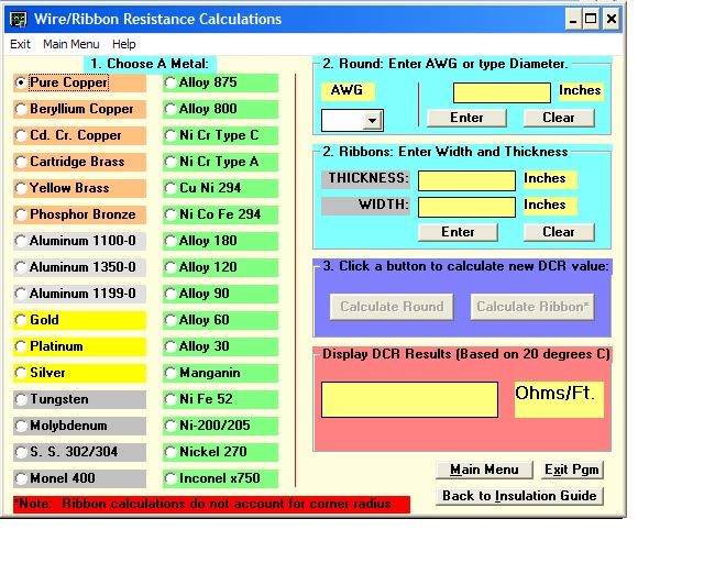
      Here is a resistance calculator for most of the common resistance materials used ...
      Litz Wire Nichrome Magnet Wire Ultra fine Magnet Wire Tungsten


      Wire: Nichrome (tm) & Other Resistance Alloys - Tech Data

      Download free software NOW. (For Windows - Only 528K) ( For above Image "Resistance Calculator" )

      I also had to order the Nickle Chromium wire from the other side of the United states 4000 miles away .... took a week ....

      Amazon.com: Nickel Chromium Wire - 20AWG, 80% Nickel Content, 1/4 LB. Spool, 79ft per Spool: Industrial & Scientific

      Metal & Alloy Wire: Nickel Material- SmallParts.com

      Nickel Chromium Wire - 20AWG, 80% Nickel Content, 1/4 LB. Spool, 79ft per Spool - SmallParts.com


      4) The potentiometer wires are a type CL2 cable, 300 Volt, 16 AWG 2-Conductor, thermostat wire. The single conductors are a type SXL "Crosslink Polyethylene" chosen for its flexibility and wire stranding in sizes AWG 12, 14 and 16 gauge.

      Glen
      Open Source Experimentalist
      Open Source Research and Development

      Comment


      • Thanks Glen for all your information.
        about 4 - i still did not understand if you think its ok to use multi-conductor cable or not, and in which sections of the circuit you used single conductor type ?
        also, the CL2 cable has multiple-strands (what i call: multi-conductor). is it good also to use single onces in the pot. connections ?
        Last edited by gadh; 04-30-2010, 07:03 AM.

        Comment


        • Yeah Glen does pretty well and every thing he does like Harvey is open source...check out the PDf on the uni site, its all Glens hard work in an AIO

          Comment


          • Weekend

            Close to the weekend now and probably finally some time to do some new measurements.

            Gadh if have to admit it, you know how to push for information …
            You are going through all the same questions and problems I had and still have.

            Glenn, thanks for all the extra information, I will probably help me too.

            Always remember, South-African pigeons can carry heavy loads over huge distances!

            Mazzeltov,
            B

            Comment


            • Originally posted by gadh View Post
              Thanks Glen for all your information.
              about 4 - i still did not understand if you think its ok to use multi-conductor cable or not, and in which sections of the circuit you used single conductor type ?
              also, the CL2 cable has multiple-strands (what i call: multi-conductor). is it good also to use single onces in the pot. connections ?
              Hi gadh,

              I see no problem using multi conductor cable on the 555 timer Potentiometers only because they really have no load involved and the only noticeable RF that was a issue for the timer circuit at the time came from the Mosfet (drain is back plane) and Heat Sink but using a "sil pad" to isolate the Mosfet, it cleared that up. I did do no testing on any RF for any possible harmful effects at the frequency's the device was operated at but will be addressing that in the Mosfet Heating Circuit thread.

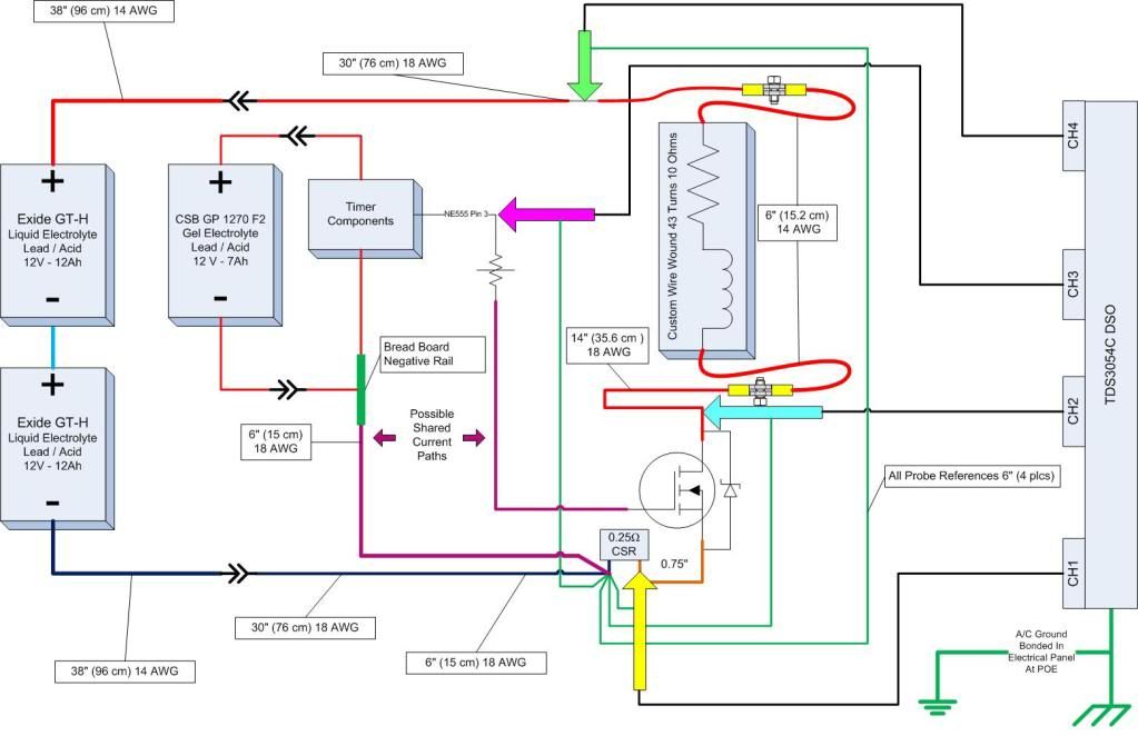
              Here is a Image that a "Harvey" a team member here at Energetic forum made showing the configuration of the experimental device and Tektronix TDS 3054C connections used in Test #13 with wire sizes and lengths.


              From Test #15 through Test #22 including all recorded videos at the "Open Source Research and Development" site, the 24 Volt battery bank positive-negative plug with the 30 inches of AWG 18 wire was removed and a DPST switch was installed and the wire changed to AWG 14 ... "NO" AWG 18 wire is present now.

              The wire lengths may seem long .... but in a "real application" there will be some distance between components, which I tried to take into consideration.

              Glen
              Open Source Experimentalist
              Open Source Research and Development

              Comment


              • Originally posted by b4FreeEnergy View Post
                Close to the weekend now and probably finally some time to do some new measurements.

                Gadh if have to admit it, you know how to push for information …
                You are going through all the same questions and problems I had and still have.

                Glenn, thanks for all the extra information, I will probably help me too.

                Always remember, South-African pigeons can carry heavy loads over huge distances!

                Mazzeltov,
                B
                Good stuff Bart. I'm even available on Sunday night this week. So. I'll be here glued and looking out for some pictures. I'll trade mine with yours and promise faithfully to post some shots of our beautiful Cape. Off topic but of general interest. LOL

                Mazzeltov B.

                Comment


                • Originally posted by ashtweth View Post
                  Yeah Glen does pretty well and every thing he does like Harvey is open source...check out the PDf on the uni site, its all Glens hard work in an AIO
                  @Ashtweth
                  ALL Glen's work? Golly.

                  Comment


                  • Originally posted by FuzzyTomCat View Post

                    1) The temperature ranges during experimentation with the present Mosfet Heating Circuit is between 140 to 160 degrees F on the exterior of the load resistor.
                    I presume this number does not take ambient into account. And that ambient under such conditions ranges at about 75 degrees F?

                    Originally posted by FuzzyTomCat View Post
                    The Borosilicate glass tube is to match any possibility of "Nickle Chromium Wire" and "Resistor Core" temperature combination which could reach easily with the materials I chosen up to 650 degrees F, for continuous operation.
                    Therefore I get it that, in these early experimental stages one only needs to ensure that the core material is non-inductive. As Gad is intending to immerse the resistor in water, then I suspect the range of choice for the core could be broader - except that it holds its 'form' to a temperature something below or just above boiling. In other words Gad, I think it's fine to 'jerry rig' something together for the base provided, as mentioned - you only use non inductive material with a core roughly proportionate to the breadth of core and width of gauge used by Glen. Just stick to those ratios - and vary whichever parameter is easiest. We at least have a ratio provided here to exploit. Given another week or so and I should be able to add some more information on this.

                    Originally posted by FuzzyTomCat View Post
                    2) I would stay at least to 27 mm if that's what you can get but size is absolutely needed for a duplicate or copy of the device replication, a 10 mm is the same size as a store bought kind and was outlined in the thread several times not to have the same circuit effect.
                    @Glen. Can you please advise if your 'big' resistor was wound with 'gaps' between the windings. You see there is another parameter at play here. It may be that those 'gaps' are required together with or to the exclusion of the diameter of the core itself. I'm not sure that this has been conclusively proven.

                    Originally posted by FuzzyTomCat View Post
                    4) The potentiometer wires are a type CL2 cable, 300 Volt, 16 AWG 2-Conductor, thermostat wire. The single conductors are a type SXL "Crosslink Polyethylene" chosen for its flexibility and wire stranding in sizes AWG 12, 14 and 16 gauge.
                    Thanks for the information Glen. Let us know about the availability of that wire Gad. I can rally if required.


                    Edited
                    Last edited by witsend; 05-01-2010, 05:41 AM.

                    Comment


                    • Originally posted by witsend View Post
                      I presume this number does not take ambient into account. And that ambient under such conditions ranges at about 75 degrees F?
                      Yes your correct about the ambient temperature being around 75 degrees F ... but the question from "gadh" was ......

                      Originally posted by gadh View Post
                      Hi Glen. i'm now trying to build the load resistor by the specs you gave, and i encountered some problems/questions:
                      1. the tube material - how much heat (temperature , celsius) must it bear ? i need to know which material i can use to build the resistor.
                      The temperature that the Borosilicate tubing and Ni Cr wire combination can go easily over 1000 degrees F or higher, without any damage far above any expectations of the Mosfet circuit possibilities. The only weak link at this point is the "High Temperature" red RTV silicone being rated at 650 degrees F used to hold the windings spaced and in place.

                      Originally posted by witsend View Post

                      Therefore I get it that, in these early experimental stages one only needs to ensure that the core material is non-inductive. As Gad is intending to immerse the resistor in water, then I suspect the range of choice for the core could be broader - except that it holds its 'form' to a temperature something below or just above boiling. In other words Gad, I think it's fine to 'jerry rig' something together for the base provided, as mentioned - you only use non inductive material with a core roughly proportionate to the breadth of core and width of gauge used by Glen. Just stick to those ratios - and vary whichever parameter is easiest. We at least have a ratio provided here to exploit. Given another week or so and I should be able to add some more information on this.

                      A non inductive core is preferred for best the best operation, I would also refrain from using any stainless steel thermocouple probes "inside" of the Load Resistor for temperature readings because the metal causes some problems in the oscilloscope performance.

                      Originally posted by witsend View Post

                      @Glen. Can you please advise if your 'big' resistor was wound with 'gaps' between the windings. You see there is another parameter at play here. It may be that those 'gaps' are required together with or to the exclusion of the diameter of the core itself. I'm not sure that this has been conclusively proven.
                      Yes there was a 1 mm gap as shown in the "Resistor Set" I used.

                      Open Source Experimentalist
                      Open Source Research and Development

                      Comment


                      • about the Ni-Cr wire

                        i have 2 factories in Israel which can possibly get me the required wire in a few days. tomorrow i'll know more details, i'll notify you.

                        Comment


                        • Through Thick Or Thin.

                          I need to clear up some rampant confusions that are referenced elsewhere on this forum. It alarms me that so much is being utterly misrepresented about the logic behind this circuit and the worst of it is that I was entirely unaware of it until recently. I trust that these errors are due to ignorance rather than otherwise. It's like asking a Jehovah's witness to give a fair account of Darwin's theory of evolution. Just not doable. One really needs to understand the logic behind a premise before one tries to test that logic with any semblance of relevance.

                          Regarding the use of thicker wire or thin. Here's the thing. My thesis proposes that the potential difference on inductive or conductive material is simply the sum of extruded magnetic fields that have been 'forced out' of the resitive material. The idea is that - given enough fields - then there's a chance at getting an appropriate 'give and take' between the resistive supply and the energy supply source - to generate the required resonance. I have NEVER advocated thick wire for puposes of generating extra heat. Rather it was proposed because the thinking is that an over supply of resistive material simply helps to test the range to get to those required oscillations. Heat is the inevitable by product. But thinner wire - on standard circuitry - would certainly generate greater heat with less current. Golly. To think that this even needs testing? We all know of this from our standard text books. It certainly does not need to be independently verified. LOL
                          Last edited by witsend; 05-01-2010, 07:16 PM.

                          Comment


                          • And more confusions - more gross misrepresentations. Golly. There are threads on this forum that show erroneous calculations of power measurements based on God knows what argument. Certainly it's not mainstream science. And for some reason these arguments remain unchallenged. It is specious - in the extreme - to propose that on this circuit one can simply take the known resistive value and then divide that by an applied voltage and then propose a correct calculation of current flow - or even an approximate calculation. Such protocols are only relevant when they are NOT applied to switching circuitry on inductive loads designed to promote resonating frequencies.

                            And then to compound these confusions - it is also seriously proposed there that the duty cycle - as represented by the waveform over the SWITCH - is the measure of the time that the battery is delivering its energy! Good gracious. These so called 'facts' have been delivered as an argument to imply that we have based our claims on erroneous measurements. What's actually erroneous are these rather adventurous calculations based on entirely incorrect, somewhat simplistic assumptions that depend on the use of hopelessly flawed measurement protocols. I have never seen the like. I'm just surprised that our talented members haven't picked up on this. Perhaps it's because they are so obviously wrong that they don't need answering. I do hope so. But it seems I need to pay attention at what is being said on other threads. There is an apparent need to belie the protocols that were applied and approved - and indeed established - by our academics themselves.

                            It constantly amazes me that there is this need to discredit this circuit technology. And all done in an arena where I cannot myself directly, address those errors. Hopefully this answer will suffice.

                            Comment


                            • Originally posted by gadh View Post
                              i have 2 factories in Israel which can possibly get me the required wire in a few days. tomorrow i'll know more details, i'll notify you.
                              Good stuff Gad. Hopefully they'll have the necessary.

                              Comment


                              • In need for a solid base to start from first ...

                                Don’t worry Rosemary; we do some thinking ourselves too. It’s not because something is written somewhere that it would be the absolute truth. For now step by step, Gadh and myself still need to see that specific oscillation getting tuned. Once that’s done and we can repeat it afterwards without too much hassle we can start thinking about how to do the heat measurement and how to do it in the right way. Gadh’s idea to submerge it completely into water might not so bad I guess. (You will not include the heat losses of the MOSFET and the shunt though) Of course you can’t measure this switched current easily in an accurate way but we will manage. There still are some friends and colleagues in the background which could help or launch a few good ideas once we’re up to it and ready.

                                Mazzeltov
                                Bart

                                Comment

                                Working...
                                X