Announcement

Collapse
No announcement yet.

COP 17 Heater | Rosemary Ainslie | Part 2

Collapse
This topic is closed.
X
This is a sticky topic.
X
X
 
  • Filter
  • Time
  • Show
Clear All
new posts

  • about your wire gauges

    Hi Glen. i saw in your color schematic diagram that you used 2 gauges for conneting the battery to the load resistor - on the positive (and also for the negative side). couldn't you use only one gauge ? is it needed for the self-oscillation or for what ?
    Comment


    • Gad-Ainslie Talk today

      Hello all.
      I've talked to Rosemary Ainslie today and I got some important tips for our work here:
      (RA = Rosemary Ainslie)
      1. RA: the wires in all the circuit should be very thick - Gad: 18AWG (1mm diameter). Glen used 18+14 AWG.
      the need for these wires is for allowing the back-emf energy delivering back to the battery form the load resistor.
      2. RA: load resistor - the most important is the spacing between the windings - at least as the wire gauge. for 18AWG = 1mm spacing. the resistance inductance values are not important. the spacing causes the resistor to gain some needed capacitance. we discovered this only lately. Gad : Though, the resistance would be quite the same for each gauge used, since it depend only on wire length and gauge.
      3. RA: the wire length is important, but only in the connection between the battery positive and the load resistor. better use 36-48 inches length.
      the other wires length is not important.
      4. measuring on the load resistor: the huge spike at the battery off time (below the zero level) should be at least 250 volts (this is the CEMF/BEMF).

      5. RA: the self-oscillation mode is mandatory for getting COP>1 (=gain), but if you use the wrong load resistor, the circuit can still be on self-oscillation mode but you won't get any gain ! so the self-osc. mode is not enough for gaining.

      6. RA :fastest method for getting to self oscillation mode - reduce the duty cycle by tuning the pot. (do not remember which one), then reduce the off period (tune the frequncy up) using the other pot. this way the on period will load the off period and we'll get close to self-oscillation. by fine tuning the pot. levels, we hopefully will get to the self-osc. mode, that will look like nice sine waves in duty cycle of about 50% (spreaded all over the scope screen like i showed in my early posts).

      i'll start now building the load resistor from scratch.

      good luck for us all and many thanks to Rosemary for her help !

      Comment


      • building the load resistor

        Glen,
        i'm having problems getting ceramic hollow core for the load resistor.
        do you think aluminum core is also good for it ?
        also, do you think i should use 20AWG as RA originally built, or 18AWG is better ? since 18AWG can deliver more amperes.
        also, i have problems getting Ni-Cr wires. can't i just use copper wires ?
        Last edited by gadh; 04-28-2010, 02:30 PM. Reason: more info

        Comment


        • load resistor self capacitance

          Hi all.
          i measured the self/parasitic capacitance of the Ainslie's original load resistor by this formula:
          C=1/(L*(2*pi*Fr)^2).
          where: Fr = the self-oscilation/resonant frequency , as stated by Ainslie - 140-200khz.
          L = the measured inductance = 8.64 mh.

          The results: at 140khz = 150 pico-farad, at 200khz = 73 pico-farad.

          please correct me if i'm wrong.

          Comment


          • Gad - I'll pm you on this but I'd rather you don't quote me - unless it's 'verbatim'. Please amend your post to read as follows:

            Originally posted by gadh View Post
            1. Connecting wires should be thick. Your suggestion of 1mm should be good. The thick wire on the resistors is preferred for experimental purposes only. It allows for a wider range to adjust for resonance. The thicker wire for the connections is simply to ensure that there's no resistance to current flow.
            2. Load resistor - It MAY be important to allow spacing between the winding. Possibly aim for the same spacing as the thickness of the wire - just as a guide. We have certainly NOT proved this. I only know that Aaron's resistors did NOT include this spacing. In as much as this is the only apparent variation between his test results and ours it may be the reason that he did not generate heat.
            3. RA: You can use a 'generous' length of wire between the battery positive and the load resistor. Up to 36-48 inches length this suggested because Glen achieved a 'higher voltage' across his resistor which may be the result of this added material. Not proved but possible.
            4. measuring on the load resistor: the huge spike at the battery off time (below the zero level) should be at least 250 volts (this is the CEMF/BEMF) assuming a 24 volt battery supply and a 10 Ohm resistor and an oscillating frequency.
            5. The aperiodic oscillation mode is required for getting COP>1. But aperiodic oscillation mode does not automatically result in gains.
            6. Tuning for resonance. We set the on time to 3% or thereby and then systematically reduced the off time. During this process you should see the duty cycle 'default' to a 50% on time which duty cycle seems to override the preset duty cycle. This is clear evidence that you are in that aperiodic oscillation mode.

            i'll start now building the load resistor from scratch.

            Comment


            • Originally posted by gadh View Post
              Hi Glen. i saw in your color schematic diagram that you used 2 gauges for conneting the battery to the load resistor - on the positive (and also for the negative side). couldn't you use only one gauge ? is it needed for the self-oscillation or for what ?
              I'd rather Glen answers this - himself, but I suspect that this helped in maintaining those higher voltage spikes - which is possibly a good thing. We only used a single gauge and somewhere between 12 - 18 inches in length.

              Comment


              • Originally posted by gadh View Post
                Glen,
                i'm having problems getting ceramic hollow core for the load resistor.
                do you think aluminum core is also good for it ?
                also, do you think i should use 20AWG as RA originally built, or 18AWG is better ? since 18AWG can deliver more amperes.
                also, i have problems getting Ni-Cr wires. can't i just use copper wires ?
                Hi Gad,

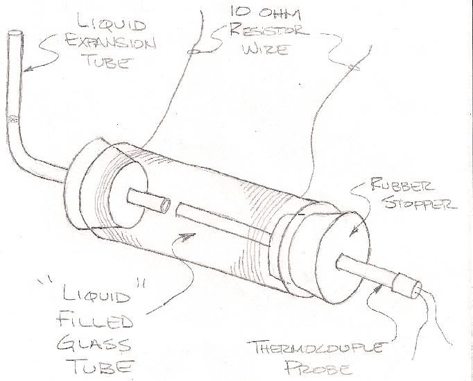
                Here is the 10 Ohm wire wound prototype "Load Resistor" that I made for the Mosfet Heating Circuit.

                I used "Borosilicate Glass Tube" ( Pyrex ) - 32 mm OD. x 6 inches long w/ 48 turns of AWG 20 [.032 dia] ( .6348 ohms ft ) "Ni Cr A" 80% nickel, 20% chromium resistance wire @ 1mm (+ -) Spacing.

                The 20 awg Ni Cr type "A" wire was chosen because of the similarity to the vague specifications in the October 2002 Quantum article this is only a best guess for the requirements needed by me.

                This is also the same materials used in the other made resistors in the "Resistor Set" that was used in most all testing.

                There is also a advantage to using the "Borosilicate" glass tubing if a alternate method of monitoring the temperature is needed.


                although there has been some problems inserting any metal inside of the resistor under operation a different type of thermocouple probe maybe required.


                Glen
                Open Source Experimentalist
                Open Source Research and Development

                Comment


                • Originally posted by witsend View Post
                  Gad - I'll pm you on this but I'd rather you don't quote me - unless it's 'verbatim'. Please amend your post to read as follows:
                  I tried to edit my previous post so it would be understood these are only my conclusions from our conversation, but for some reason it was not saved. sorry for that again.

                  Comment


                  • Glen, Bart - could you please give me your Skype usernames (in PM) so we can coordinate our efforts more quickly ?

                    Comment


                    • Originally posted by gadh View Post
                      Hi Glen. i saw in your color schematic diagram that you used 2 gauges for conneting the battery to the load resistor - on the positive (and also for the negative side). couldn't you use only one gauge ? is it needed for the self-oscillation or for what ?
                      Hi Gad,

                      The experimental replication went through many small changes in the 6 months of testing and evaluation of the circuit, plus all the connections were soldered together. In a attempt to save some components from any damage and not knowing what wire sizes to use thinking the "Mosfet" is rated at around 6 amps the load resistor is #20 AWG that a #16 AWG CU would be sufficient for the entire circuit, but because of the inductance, some wire sizes needed to be increased in the 24 Volt portion of the circuit.

                      I would assume that a #12 AWG CU wire in the 24 Volt portion would be sufficient for this circuit as it is now.

                      Glen
                      Open Source Experimentalist
                      Open Source Research and Development

                      Comment


                      • Originally posted by FuzzyTomCat View Post
                        Hi Gad,

                        Here is the 10 Ohm wire wound prototype "Load Resistor" that I made for the Mosfet Heating Circuit.

                        I used "Borosilicate Glass Tube" ( Pyrex ) - 32 mm OD. x 6 inches long w/ 48 turns of AWG 20 [.032 dia] ( .6348 ohms ft ) "Ni Cr A" 80% nickel, 20% chromium resistance wire @ 1mm (+ -) Spacing.

                        The 20 awg Ni Cr type "A" wire was chosen because of the similarity to the vague specifications in the October 2002 Quantum article this is only a best guess for the requirements needed by me.

                        This is also the same materials used in the other made resistors in the "Resistor Set" that was used in most all testing.

                        There is also a advantage to using the "Borosilicate" glass tubing if a alternate method of monitoring the temperature is needed.


                        although there has been some problems inserting any metal inside of the resistor under operation a different type of thermocouple probe maybe required.


                        Glen
                        Hi Glen.
                        could you calculate the COP levels you got for each load resistor you built ? prefferably in the same test ?

                        Comment


                        • Hi Glen.
                          I understand that some wires should be thicker in the 24v portion. what i do not understand is why you switched gauges in the middle of the wire ? (in the middle between the battery positive and the load resistor). shouldn't you simply connect the wire straight from the battery to the load resistor without switching wires in between ?

                          Comment


                          • Originally posted by gadh View Post
                            I tried to edit my previous post so it would be understood these are only my conclusions from our conversation, but for some reason it was not saved. sorry for that again.
                            Hi Gad. Not a problem. Just for future reference it sometimes sticks on the 'edit' function and you may need to go 'advanced'. But regarding the 'misquotes' - it's not serious. I think my own post clarified things.

                            Don't bother.

                            I've got a set of results posted on this thread on Glen's test. But they're only evaluated on the 'multiple sample' data dumps. I'll see if I can find them. Otherwise, perhaps Glen can post the results from our paper. Either way I'll get the results over before I go to bed.

                            You're tireless here - Gad. It's a good thing.

                            Comment


                            • Originally posted by witsend View Post
                              And here's a preliminary revised evaluation of the tests taken on Glen's replication

                              TEK00000 - 0.00 WATTS
                              TEK00002 + 3.59 WATTS
                              TEK00004 + 2.46 WATTS
                              TEK00006 - 0.87 WATTS
                              TEK00008 - 0.04 WATTS
                              TEK00010 + 4.91 WATTS
                              TEK00012 - 0.17 WATTS
                              TEK00014 - 0.09 WATTS
                              TEK00016 - 0.71 WATTS

                              TEK00018 - 0.42 WATTS
                              TEK00020 - 0.12 WATTS

                              average performance over the entire test period was, therefore 0.822 watts.
                              Heat dissipated was an average of 5.5 Watts.
                              THEREFORE COP > 6.23 OR 669%

                              No heat profile was conducted on the mosfet arrangement and the attached heat sink nor on the shunt resistor. Yet there was clear measured evidence of heat being disipated at both points. Temperature measured at both points was higher than evidenced at the load. If these values were also factored in as wattage dissipated at a conservative three quarters of the wattage at the load then the actual wattage dissipated as heat would have been 5.5 * 75% plus 5.5 being 9.62 Watts. This would place COP at anything between 6.23 and 11.7.

                              It is not an ideal test evaluation. Ideally the test should be run and data logged continuously over an extended period of time. But this was not possible given the equipment available. However, what is significant is that there were any records at all of negative wattage delivered. This should not be possible according to mainstream predictions. Yet it is clearly a predominant condition of this circuit. It is also evident in the occassional recharge of the battery which is not typically known to climb when run under load conditions.

                              What is signficant is that any value of wattage that is recorded to be greater than COP 1 is quite simply not expected within classical prediction on this circuitry. And measurement of temperature rise is widely considered to be sufficient proof of the wattage dissipated. Therefore, in all cases and under all possible conditions, this circuit is capable of exceeding classical prediction even under the most conservative assessment. And this using classical measurement protocols.

                              These measurements were confined to multiple waveform sample range which is required for 'proof' of data. Faster time scales or fewer samples fall outside the range of accuracy required by Tektronix.
                              Gad - here's our analysis of Glen's results on his TEST 13. Hope that helps and sorry I've only just got around to it.

                              Let me know if you've got difficulties. My day is pretty full but I'll be able to drop in here off and on. Take care and Good luck in putting all this together.


                              edited. By the way. You'll notice that the amount of energy delivered NEVER exceeded the amount of energy dissipated and measured as temperature rise over the load resistor. It seems to be a condition of this aperiodic oscillation that it keeps returning that energy. We are not certain of ALL the required conditions to reach this state of resonance. But the scope to find it is enhanced if the range of adjustment is increased. That's definitely enabled with thicker rather than thinner resistance wire.
                              Last edited by witsend; 04-29-2010, 06:49 AM.

                              Comment


                              • the specifications of the load resistor + more

                                Hi Glen. i'm now trying to build the load resistor by the specs you gave, and i encountered some problems/questions:
                                1. the tube material - how much heat (temperature , celsius) must it bear ? i need to know which material i can use to build the resistor.

                                2. i can only use 27mm diameter tube for some technical reasons. do i have to use more turns in order to keep the inductance/resistance level as same as possible to the original values ? by how many ?
                                2a. can i use even smaller diameter ? 10 mm ?

                                3. i have problems getting this type of wire you used. can i use copper instead ? or other suggestions ?

                                4. about the wiring in the power side of the circuit - battery, load resistor, MOSFET (left side): can i use multiple-conductor (multi-cord) cable or just single-conductor type ? what type did you use ?
                                Last edited by gadh; 04-29-2010, 08:04 PM. Reason: be precise:

                                Comment

                                Working...
                                X