Announcement

Collapse
No announcement yet.

COP 17 Heater | Rosemary Ainslie | Part 2

Collapse
This topic is closed.
X
This is a sticky topic.
X
X
 
  • Filter
  • Time
  • Show
Clear All
new posts

  • Originally posted by b4FreeEnergy View Post
    Don’t worry Rosemary; we do some thinking ourselves too. It’s not because something is written somewhere that it would be the absolute truth. ...

    Mazzeltov
    Bart
    I know this of you B. You're trained in measurement protocol. Anyone trained in these things will immediately pick up on those errors. But not all our members are. So I get anxious when I see incorrect measurements protocols being submitted as reliably correct. Fortunately, as you point out, those readers with the required training - will simply see it for the nonsense that it is. But that's no comfort if it also serves to misguide our own members who perhaps do not have that training.

    The thing that puzzles me is that I was given to understand that the thread was 'required' to advance much needed experimentation. But I see NONE. Or rather I see no tests on the actual switching circuit. All I actually read is a continuing attack on my thesis and on this application. Indeed, the only test that is also fully described was a 'failed' test and it's easy to 'fail' this. One just needs to adjust the duty cycle to secure a bad frequency and failure will follow as day follows night. One hopes it was not intended.. It now appears that if some arbitrary test is performed on a resistive winding - that does not generate an appropriate heat - applied through an UNSWITCHED system - it will then conclusively prove that the model is wrong. And the model is rather scathingly referenced as my 'superluminal zipons'. Why is that model being discussed at all? It's elsewhere regarded as irrelevant and immaterial to the effect? Yet here it's even being evaluated. And in terms that 'brook no argument'. It's an argument that is presented with apparent authority when in fact there is none.

    I also read of a raft of tests that are proposed to determine the effective 'heating' over a range of wires - using STANDARD energy supply sources - for goodness sake. This to disprove some claim that I have NEVER made that the heat is better dissipated through thicker wire. And all this on a thread where 'membership' is required to determine the caliber of the contributors and their compliance to 'on topic' discussion of the so called 'mosfet heating circuit' - a misnomer in and of itself. And the final irony. I myself, who actually authored this maverick benefit in switching circuits - may not 'speak' on that thread.

    Frankly I still find myself drowning against this flood of misinformation because I simply cannot get the air required to counter these attacks. My hope is that it will finally be silenced when we get our hot water application up and tested.

    As an update - we are due to take delivery of our cylinder sometime during next week. Only then will I be in a position to get the resistor designed - at this stage intended as a single straight rod. But we will probably need to test a variety of windings. We've had to modify the original design - marginally - to cater to the concerns of the manufacturer. But - effectively - we'll have the first 'test' apparatus and that will have the added merit of being scaleable. Any advances on that required resonance will obviously be shared. This last week has been slow - a short week because of a holiday.
    Last edited by witsend; 05-02-2010, 07:21 AM.

    Comment


    • Here's mine B. Now show us yours!


      EDITED.
      Sorry for it's apparent 'off topic' subject matter here. But the fact is that this is submitted as 'barter' for some of Bart's own pretty pictures that will have the real merit of being very much on topic. LOL.


      Sorry. I should have said - it's some local scenery - the foothills to the Boland Mountains. About 2 k's from where I live - plus/minus 15 ks to the sea - and about 20 k's from Cape Town Centre.
      Last edited by witsend; 05-03-2010, 05:51 AM.

      Comment


      • Originally posted by b4FreeEnergy View Post
        There still are some friends and colleagues in the background which could help or launch a few good ideas once we’re up to it and ready.

        Mazzeltov
        Bart
        B. I entirely overlooked this. THIS SOUNDS WONDERFUL. You'll see difficulties in getting an appropriate transistor. But we're simply 'starting' a single application but on a small scale. In Africa there's a ready market for 5 litres - indeed even 1 litre of hot water. Not so sure that it's a need in our first world countries. But it's scaleable and, personally, I see plenty that will then motivate our mosfet manufacturers to make some heavy duty numbers. That way it can get broader applications.

        EDITED

        Comment


        • Got something ...

          Before I start with my ‘office’ work I thought it might be a good idea to post my results of the weekend. I studied the scope dumps Glen posted in more detail and to my surprise I found out that he has his 555 running at a frequency close to 36 kHz or something. That’s not what the 555 generates if you apply the posted schematic in an unmodified way. But ok I thought it was worth giving it a try so I increased the frequency of my 555 and started tweaking and to my surprise it suddenly jumped into that most wanted oscillation mode.
          Since I don’t have a 3th 12V battery yet, I did use my lab power-supply to feed the 555, this might have had some influence on my results so I still have to do it all over again with batteries only. I did a quick test connecting the 555 to one of the batteries of the 24V bank but could not get the circuit back into oscillation that way yet. I’m recharging the batteries now and hope I can do some more tests later on today and have the same results without that lab power-supply.
          On the pictures you can see that I removed my 555 from its original position and did the circuit all over on the white ‘breadboard’. The scope screen shots show the original frequency on my 555 and its duty cycle and when it went into oscillation. (215kHz)
          All this has to be double checked and confirmed but at least I got something now.

          Mazzeltov
          Bart


          Comment


          • Hi Bart,

            THOSE ARE WONDERFUL SHOTS and CLEAR PROGRESS. VERY WELL DONE. AND MANY MANY THANKS FOR THE PICTURES.

            I've got lots to do but will study this all when I get back. What a pleasure.


            Comment


            • Hi Bart. I can't quite work out if you're in positive territory there. Some waveforms do look more promising. How many samples do you need for accurate analyis on your machine? And can you do some muliple samples to see if we've got any harmonics in that oscillation? But it looks REALLY PROMISING. Interesting to see that it's not that 'easy' to find this. I really need to stress this point for Gad and others who may want to test this. I was at an advantage because I was really looking for the effect. But even then - our best came late in the day. Is is fair to say that one must just pay close attention to the waveforms? I know it's a fine tuning that gets one there.

              Well done indeed Bart. So nice to see this. Now I suspect you'll need some fine tuning.

              Comment


              • Guys, I've learned today that the circuit is actually deceptively simple. To get to the required oscillations takes some considerable talent and the actual tuning - which is 'key' to the effect - is more elusive than I realised. The thing is that these aperiodic oscillations are well known. Professor Horrowitz, for instance, actually refers to them in his 'text book' on electronics. But his reference is simply to advise his students how to 'get rid of them' in the unhappy event that they stumble on this. In other words - classical and mainstream's only reference to this chaotic condition is to 'kill it on sight'. It's very easily got rid of. Simple application of pressure - anywhere on the circuit wiring and the effect is lost.

                My own experience of this is that having 'found' that oscillation - it was very easy to 'tune it in'. But it was so simple that I never realised that 'yet' it is hard to find. I'll give an example. A colleague of mine who did multiple testing on my own circuit then built and tested his own circuit - and could not find the oscillation. He brought it here to check it against my own circuit and - without changing any of the circuit components we found the oscillation on his circuit as well. Thereafter it was easy for him to get it into resonance. The same with Glen. He also struggled initially. But having found that 'moment' he was easily able to 'repeat' the event. It sort of 'lurks in the shadows' until it's finally exposed. And then it also, happily, is easy to get to.

                I can't explain this. And to any others who struggle for this effect - I can only ask that you to 'hang in' there. I suppose a 'guide' would be to systematically vary those duty cycles - starting at a small 'on' period and working upwards from there. I am reasonably certain that all such circuits can be tuned into an aperiodic oscillation. But it clearly requires a little patience.

                EDITED. Perhaps Bart can give us all some tips here.
                Last edited by witsend; 05-04-2010, 03:54 PM.

                Comment


                • I also need to bring your attention to some required parameters for actually testing the data. Most storage oscilloscopes will advertise the number of samples required to get an accurate gauge of the voltages measured anywhere on any circuitry. Most also rely on multiple sample ranges in order to get to a dependable value or to the required level of accuracy. This circuit has an aperiodic oscillation. This means that virtually no two wave forms are alike. The one may measure a loss the other a gain - and the one can follow directly after the other. Measurement is complex. Because of these variations - and on this type of waveform - it is critical to get as wide a sample range as is recommended by the manufacturers of those DSO's or DPO's. Anything below 100 samples may offer an interesting result but it is unlikely to have any real bearing on the energies measured to be delivered or dissipated. Therefore, to those who are doing analysis on these waveforms, may I urgently request that you FIRST get to that number before going to the trouble of computing the results. Unless it's got the required sample range any results are entirely suspect and may not have much bearing on the actual values.

                  It is also due to this 'gross' variable condition of the waveforms that it would be impossibly 'slow' to compute and measure each and every waveform using any standard protocols. This is one function that depends on computer analysis - else it would take a month of Sundays to evaluate any single data dump.

                  Comment


                  • Regarding any actual measurement of the energy dissipated at the load - this too is complex. There is, self-evidently, much more energy being dissipated than is evident in heat. Heat is definitely a by product. The rest seems to be in RF. Perhaps, in due course, some application can be engineered that also includes some modified microwave technologies - just to make better use of this. But that would need to be a second phase to these applications. There's plenty of exploratory work required. Right now - the idea is to harness that excess heat and make good use of it.

                    Comment


                    • Hi everyone,

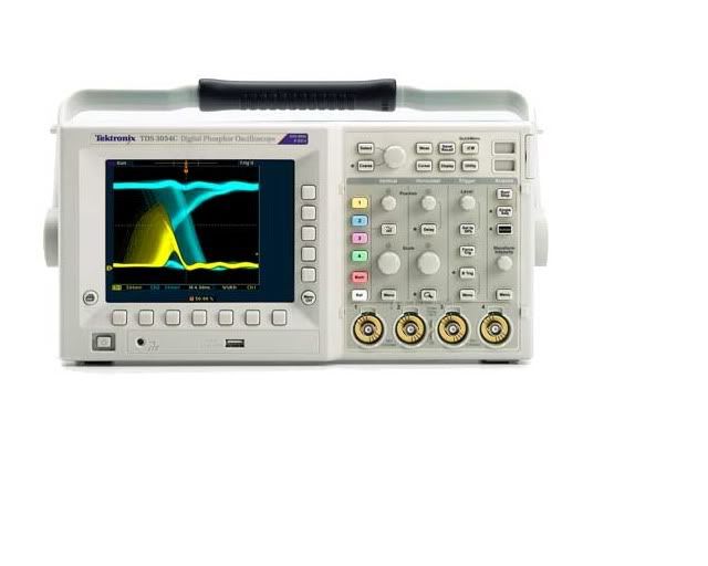
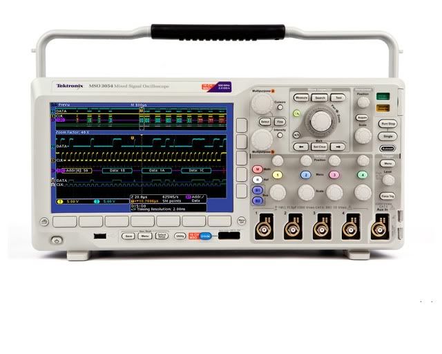
                      These are the oscilloscopes I used on my Videos, testing and evaluation of this circuit so far ....

                      TESTS #1 through TEST #15

                      Model - Tektronix TDS3054C
                      Bandwidth - 500 MHz
                      Sample Rate - 5.0 GS/s
                      Record Length - 10 k
                      Channels - 4


                      TDS3000C Digital Phosphor Oscilloscope Series > Products : Tektronix
                      Tektronix TDS 3054C - Operation Manual and Specifications - PDF


                      TESTS #16 through TEST #22

                      Model - Tektronix DPO3054
                      Bandwidth - 500 MHz
                      Sample Rate - 2.5 GS/s
                      Record Length - 5 M
                      Channels - 4


                      MSO/DPO3000 Mixed Signal Oscilloscope Series : Tektronix
                      Tektronix DPO 3054 - Operation Manual and Specifications - PDF


                      Model - Tektronix 2445a
                      Bandwidth - 150 MHz
                      Channels - 4

                      Tektronix 2445A - Operation Manual and Specifications - PDF

                      Glen
                      Open Source Experimentalist
                      Open Source Research and Development

                      Comment


                      • @ Glen. I think what's needed here is complete restoration of all the scope shots together with easier access to data analysis - if you wouldn't mind.

                        But thank you for these links. What's needed is that data that you originally showed on these threads. They're just not as visible as required and - personally - I still cannot access the spreadsheets. Can we all impose on you here Glen? It would be of some considerable interest and I think our viewers would appreciate clearer direct reference to that data. I know I've been approached to ask you this - often.

                        Kind regards,
                        R.
                        Last edited by witsend; 05-05-2010, 09:43 AM. Reason: ambivalence

                        Comment


                        • Originally posted by witsend View Post
                          @ Glen. I think what's needed here is complete restoration of all the scope shots together with easier access to data analysis - if you wouldn't mind.

                          But thank you for these links. They're just not as visible as required and - personally - I still cannot access the spreadsheets. Can we all impose on you here Glen? It would be of some considerable interest and I think our viewers would appreciate clearer direct reference to that data. I know I've been approached to ask you this - often.

                          Kind regards,
                          R.
                          There is a link in this thread to all my images and data ..... POST 297

                          I've been Quite busy lately with many other projects and because of the bandwidth usage where my off site photo storage was it got to the maximum monthly use any more and I would have to pay for image and photo access for everyone, so now all my Tests are in a zip files each complete with "Original" photos, images and data dump sheets w/ test keys & temperature data, and at this time I can only offer my Windows Live "SkyDrive" public file, that has all the information available. Plus some interesting "public" folders available on other subjects and projects.

                          Mosfet Heater Folder

                          The best I can do.
                          Open Source Experimentalist
                          Open Source Research and Development

                          Comment


                          • Originally posted by FuzzyTomCat View Post
                            There is a link in this thread to all my images and data ..... POST 297

                            I've been Quite busy lately with many other projects and because of the bandwidth usage where my off site photo storage was it got to the maximum monthly use any more and I would have to pay for image and photo access for everyone, so now all my Tests are in a zip files each complete with "Original" photos, images and data dump sheets w/ test keys & temperature data, and at this time I can only offer my Windows Live "SkyDrive" public file, that has all the information available. Plus some interesting "public" folders available on other subjects and projects.

                            Mosfet Heater Folder

                            The best I can do.
                            I would be well able to post those screenshots here if you have no objections?
                            Obviously they will be referenced as your work.

                            Comment


                            • Originally posted by witsend View Post
                              I would be well able to post those screenshots here if you have no objections?
                              Obviously they will be referenced as your work.
                              I would prefer you not post my work, Thank You
                              Open Source Experimentalist
                              Open Source Research and Development

                              Comment


                              • Originally posted by FuzzyTomCat View Post
                                I would prefer you not post my work, Thank You
                                While I entirely respect your decision here is there a reason for this? I would have thought that any such illustrations would help some of our forum members who are planning on replications of this circuit. And it is surely in the interests of Open Source to get as much information as possible into the public arena. You see - it'll be a guide to show our members what to look for. It's an unfortunate reality that we did not make copy of our waveform in our earlier tests. Having now learned of this need - I will certainly do this in our own tests on the application. But that's at least a while away. We're only getting delivery of our copper cylinder during the course of this week. Then we have to design and build a few resistors for testing. And then only will we be in a position to attend to the switching requirements and the supply sources. I'd guess that's about 3 weeks away yet - at best. It would assist 'pro tem'? But if you feel some need to protect this information then I can respect that too. But it would be nice to have some explanation for this.

                                Comment

                                Working...
                                X