Reed Relay Ignition coil 555 circuit
[ATTACH]5410[/ATTACH]
[ATTACH]5411[/ATTACH]
[ATTACH]5412[/ATTACH]
Hi all, I thought I would post these pictures of a circuit I built some time ago , as it seems relevant at the moment, and maybe someone can help me to understand it better.
First - the breadboard shows a neat , cheap way of getting variable capacitance over a wide range. Pin2 of the 555 is connnected to the DIP switch bank -it is then possible to insert any desired capacitors , and parallel any combination of them ,to obtain any desired value. There are 7 caps in the bank here - the 8th swich was used for a variable cap ,to fine -tune the final value, but it is now soldered into another circuit.
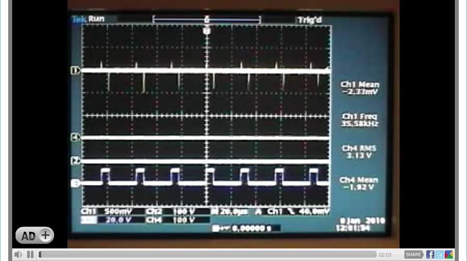
This circuit functions as follows : 6v battery powers 555 circuit.- output @pin3 [bottom trace of scope ], switches a reed relay.
12v battery is in series with power limiting potentiometer, reed relay contacts ,and primary of outboard motor ignition coil
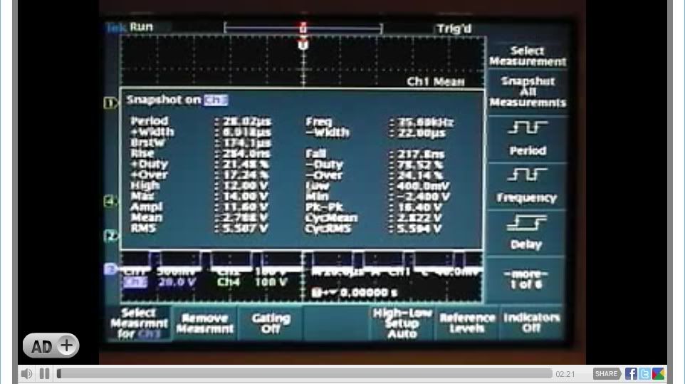
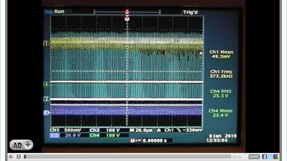
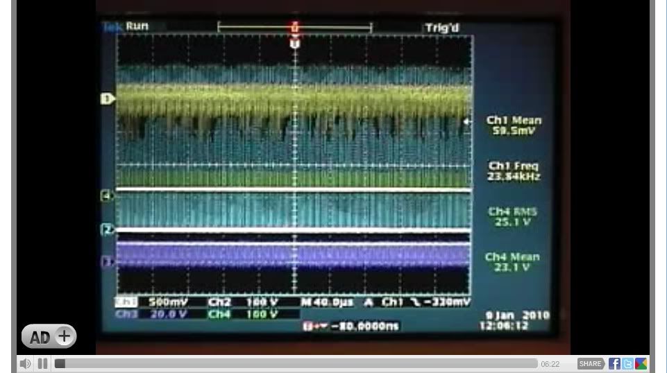
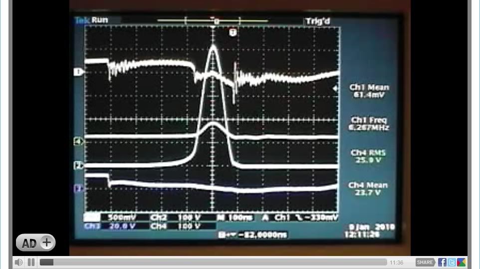
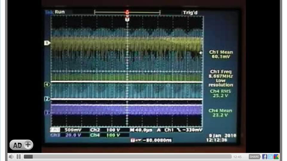
Secondary of coil is discharged through either a spark gap alone [ can be seen glowing], or spark gap + diode. This is the top trace on the scope, and the v/division is 50v. It clearly shows that the spikes are chopped by the spark gap @75v. If the gap was not there the spikes would be over 2000v.
The time it takes to activate the relay is clearly seen. The AC ringing is clearly seen.
The charging of the relay coil APPEARS to be capacitative?
The discharge of the coil is inductive, but there APPEARS to be more energy expended than input if the AC ringing is taken into account.
I use a variation of this circuit for mosfets - so any comments will be very welcome.
Chris




 And BTW, it only gets better for us if we conclude the battery voltage should be lower than 10V when discharged
  (of course we all know that the battery voltage needs to be measured under specific load conditions)
Comment