Hi everyone,
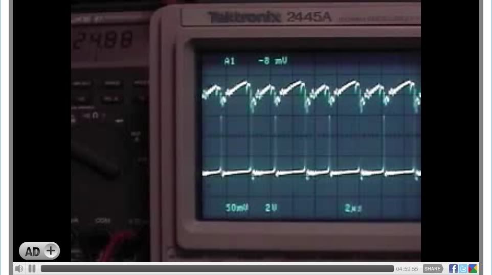
This post is a recap of a "LIVE" recording at "Open Source Research and Development" channel which was a 5-hour non stop recording on January 24, 2010 using a Tektronix 2445A Oscilloscope.
Please see the Image time bars for actual recorded time in hours, minutes and seconds.
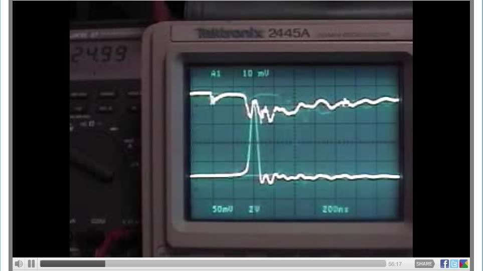
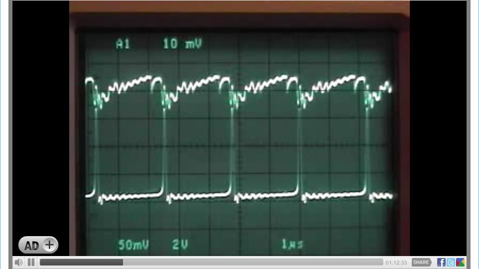
Channel 1 - Mosfet Source Pin 50 Mv (x10)
Channel 2 - 24 Volt Battery Bank 2 V (X10)
Scope Trigger - Channel 1 (A1) "FALLING" signal slope [ \ ] "IMPORTANT"
"START"
First the 12 Volt battery was connected to 555 timer circuit "only" and pre adjusted, the "ON" potentiometer to minimum resistance (0), the "OFF" potentiometer adjusted to maximum resistance (2K), resulting duty cycle is at about 21.48 %
Second the 24 Volt battery bank is connected, The circuit now defaults to a 50 - 55 % duty cycle, no further "ON" or "OFF" potentiometer adjustments are needed. Then by adjusting the "GATE" potentiometer "only" using the oscilloscopes 200ns division for minimum Mosfet source Mv and two (2) divisions from the "OFF" signal to the 24 Volt Battery signal "spike" combined with the Fluke 87 DMM highest voltage reading connected to the 24 volt battery bank.
The device circuit is 100 % fully functional in the preferred mode of operation and under "load" the 24 Volt Battery bank.
Voltage is now at 25.00 DC Volts with no further adjustment to be made on any of the circuit potentiometers.
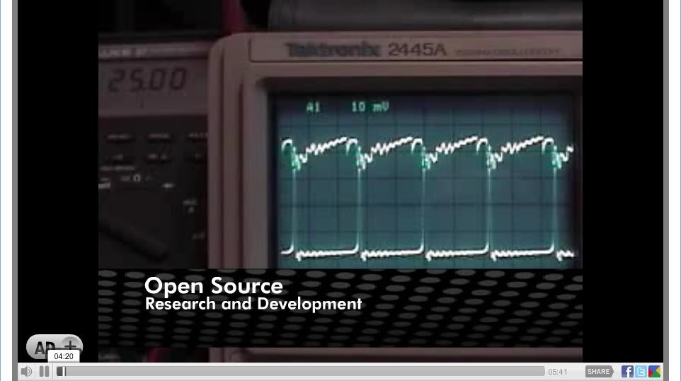
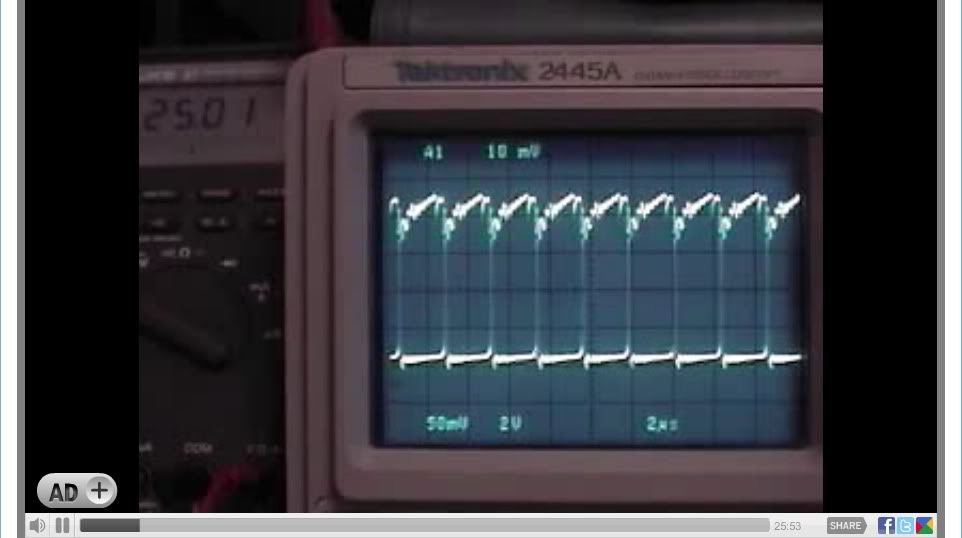
A now recorded 24 Volt battery bank voltage increase seen on the Fluke 87 from the starting voltage of 25.00 to 25.01 DC volts.
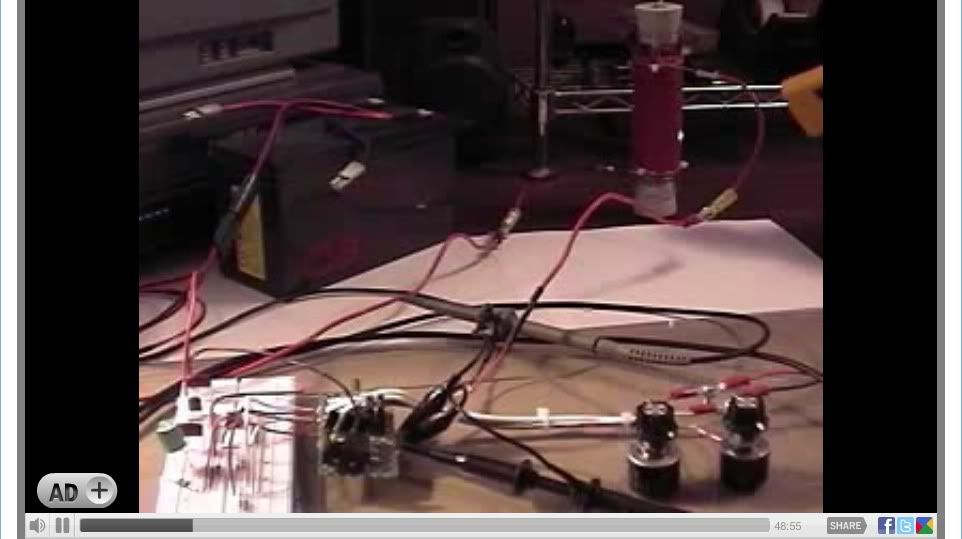
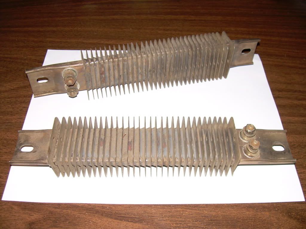
A look at all the circuit components and temperature readings of the Load Resistor, Mosfet and Shunt Resistor.
The oscilloscope at the 200ns division selection with two (2) divisions from the Mosfet source "OFF" signal to the 24 Volt Battery signal "spike" combined with the Fluke 87 DMM highest voltage reading connected to the 24 volt battery bank.
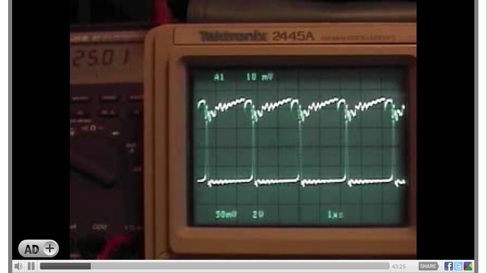
The oscilloscope at the 1us division in the circuits preferred mode oscillating normally
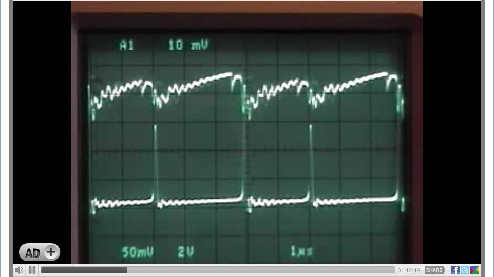
"FINISH"
Now after approximately 5-hours of continuous operation the 24 Volt battery bank voltage has dropped from the Starting voltage of 25.00 to 24.88 Volts DC, a total decrease of .12 Volts DC under load, maintaining a 140 to 145 + degree F temperature on the "Load Resistor" which is about 5.5 watts continuous load.
Best Regards,
Glen

This post is a recap of a "LIVE" recording at "Open Source Research and Development" channel which was a 5-hour non stop recording on January 24, 2010 using a Tektronix 2445A Oscilloscope.
Please see the Image time bars for actual recorded time in hours, minutes and seconds.
Channel 1 - Mosfet Source Pin 50 Mv (x10)
Channel 2 - 24 Volt Battery Bank 2 V (X10)
Scope Trigger - Channel 1 (A1) "FALLING" signal slope [ \ ] "IMPORTANT"
"START"
First the 12 Volt battery was connected to 555 timer circuit "only" and pre adjusted, the "ON" potentiometer to minimum resistance (0), the "OFF" potentiometer adjusted to maximum resistance (2K), resulting duty cycle is at about 21.48 %
Second the 24 Volt battery bank is connected, The circuit now defaults to a 50 - 55 % duty cycle, no further "ON" or "OFF" potentiometer adjustments are needed. Then by adjusting the "GATE" potentiometer "only" using the oscilloscopes 200ns division for minimum Mosfet source Mv and two (2) divisions from the "OFF" signal to the 24 Volt Battery signal "spike" combined with the Fluke 87 DMM highest voltage reading connected to the 24 volt battery bank.
The device circuit is 100 % fully functional in the preferred mode of operation and under "load" the 24 Volt Battery bank.
Voltage is now at 25.00 DC Volts with no further adjustment to be made on any of the circuit potentiometers.

A now recorded 24 Volt battery bank voltage increase seen on the Fluke 87 from the starting voltage of 25.00 to 25.01 DC volts.


A look at all the circuit components and temperature readings of the Load Resistor, Mosfet and Shunt Resistor.


The oscilloscope at the 200ns division selection with two (2) divisions from the Mosfet source "OFF" signal to the 24 Volt Battery signal "spike" combined with the Fluke 87 DMM highest voltage reading connected to the 24 volt battery bank.

The oscilloscope at the 1us division in the circuits preferred mode oscillating normally


"FINISH"
Now after approximately 5-hours of continuous operation the 24 Volt battery bank voltage has dropped from the Starting voltage of 25.00 to 24.88 Volts DC, a total decrease of .12 Volts DC under load, maintaining a 140 to 145 + degree F temperature on the "Load Resistor" which is about 5.5 watts continuous load.

Best Regards,
Glen


 I²R tells us the power in FET, where it is 2 Ohms ON, to be 74.42W if the current were continuous DC. So it would get pretty warm even during normal operation. Devices with lower on resistance, or parallel MOSFET's can greatly reduce that dissipation loss.


Comment