Announcement

Collapse
No announcement yet.

trifilar bedini SG motor Help!

Collapse
X
 
  • Filter
  • Time
  • Show
Clear All
new posts

  • trifilar bedini SG motor Help!

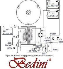
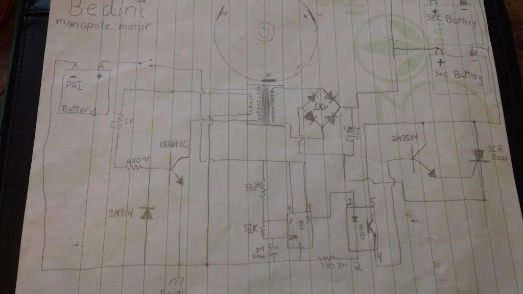
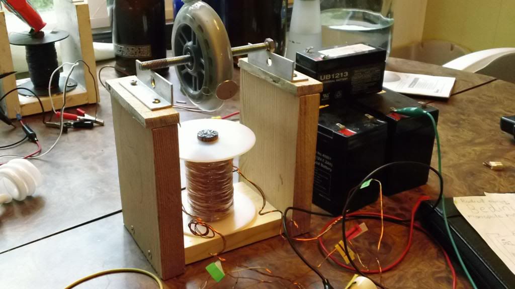
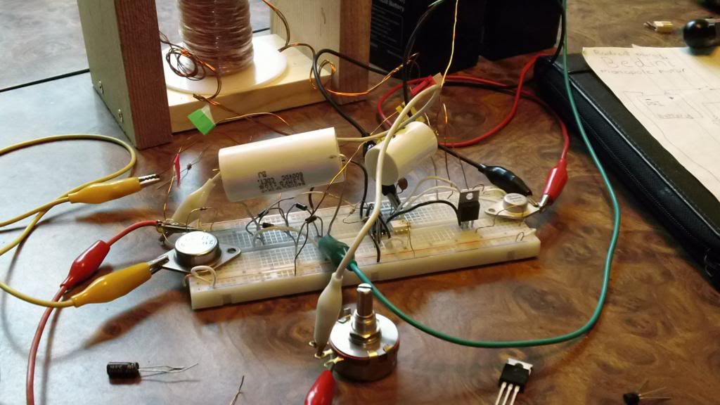
    Does anyone have any info that might help me with building this trifilar bedini motor? All iv had to go by is a picture of the circuit and i haven't been successful yet. the trifilar coil is new from Bedinis r-charge site, I'm wondering if there's a specific order that the coil wire must be wired to the circuit? i have built the circuit as the picture shows it, assuming the picture is correct I'm thinking that maybe my wheel is to small? or the magnets are to strong "neodymium". the gap from coil to magnet is around 1 inch. does the circuit need to be ground to earth for there to be wheel movement? With all my other projects this has not been the case, I'm completely stuck on this project please help! I would really like to show this project off at burning man this year.


  • #2
    Hi Seen3708,

    to the forum. I'll try to answer your questions. Yes there is a certain way to hook up the wires from the coil. You might try swapping the 2 wires for the trigger part of the circuit. The trigger circuit has to put the right voltage to the base of the transistor to turn it on. Before you do that you should narrow the gap between the magnets and the coil. The gap should be about 1/8th of an inch to 3/8ths . Somewhere in there should get it working if all else is OK. Neo magnets are not recommended. Ceramic magnets work better, but you should still be able to get it to run with neos it just won't be as efficient. Your wheel is not too small. I have seen many of them with wheels that small and have built some only slightly bigger than yours. They all ran fine.

    I do see a couple of other things in your pictures that don't look quite right. It looks like you only have the magnets glued onto the wheel. If you get the wheel to run a small wheel like that can get up to several hundred RPMs and those magnets can fly off like a bullet. You really need some strong shipping tape or something wrapped around the outside of the magnets like you have on the wheel in the background.

    Also in the picture it looks like the wires coming from the coil at the top and going towards the right side of the picture are all twisted together where they go behind the black wire. If that is so then you have the three coils shorted together and that will not work. All three coils must be electrically isolated from one another.

    The power coil also has to be connected correctly for the circuit to work. You can test it very easily. With a magnet over the coil turn on power to the circuit. Then use a jumper to connect from the collector of the transistor to the emitter. If the power coil is connected correctly the coil will then kick the magnet away. Also I guess you know you have to start the wheel by hand. It will not start on it's own. You have to give it a pretty good spin to get it going. The reason for this is to generate the voltage needed to go to the base of the transistor to turn it on.

    I hope these ideas have helped some.

    Respectfully, Carroll

    PS: You need to get rid of as many of those jumper leads as you can. They only cause problems with bad connections. Try to solder as much of the circuit together as you can.
    There are many good tutorials on the net to teach you how to solder if you don't already know how.
    Just because someone disagrees with you does NOT make them your enemy. We can disagree without attacking someone.

    Comment


    • #3
      thank you for your help, unfortunately after replacing clip leads, fixing / checking coil wires, switching trigger wires (top to bottom) and testing power wire all checks out but still no movement. I think I'm down to two possibilities, One of the electrical components are not working correctly or i have wired the 555 timer incorrectly some how. I'm still not to familiar with the 555 timer. I'm kinda a self taught hands on kinda guy so i apologize but if you could take a look at this video and point me in the right direction i would be extremely grateful. It seems to wanna work but something is getting in the way. after accidentally getting the coil to hum after connecting it to power i decided to get my "bedini Radio out" to see what i could hear. As you can see on the video the circuit is emitting a RF right? is that normal? should i change the trigger resistance?

      MAH00826 - YouTube

      <iframe width="560" height="315" src="http://www.youtube.com/embed/lJyb0hfuves" frameborder="0" allowfullscreen></iframe>

      Comment


      • #4
        Hi again,

        You did not show in your video what happens when you give the wheel a spin. I don't think anything in the 555 part of the circuit would keep the wheel from spinning. The 555 circuit is only for dumping the charged up cap to the charge batteries. We have to get the wheel spinning before the cap will charge from the bridge rectifier and the extra coil winding. You will need to adjust the pot in the trigger circuit to get the best operation and you might have to adjust it just to get it to run since you are using neo magnets. You also might have to lower the 680 ohm resistor to 100 ohms to get it to run.

        You said you checked the power winding. Did it kick the magnet away when you jumpered from the collector to the emitter? If it did then the problem is in the trigger circuit or the transistor is bad. If the power winding kicked the magnet then I would lower the resistance of the pot to it's lowest setting and give the wheel a hard spin and see what happens. If it still doesn't go I would just temporarily jumper across the 680 resistor and try again. If it still doesn't go then switch the trigger wires again and try spinning the wheel again. Once you get it running do not leave the jumper across the 680 ohm resistor as you might over heat the transistor by driving it too hard. If it works with the jumper then change the 680 ohm resistor for a 100 ohm resistor and then try again. If it doesn't work with a jumper across the resistor and the pot turned all the way down and after you swapped the trigger wires then you probably have a bad transistor. I hope these ideas get you going. I only check on here a few times per day so if I don't answer right away just hang in there and I'll get back to you when I get a chance. I have helped many other people on this forum to get theirs working so I am sure we can get yours going too.

        Later, Carroll

        PS: Did you decrease you gap between the magnets and the coil? It is hard to tell from the video but it still looked kind of wide. It should be around 1/4 inch or so give or take 1/8 inch.
        Just because someone disagrees with you does NOT make them your enemy. We can disagree without attacking someone.

        Comment


        • #5
          Well your suggestions are getting me closer every day I'm really excited about getting this motor running. When we last talked the wheel didn't do anything regardless of how hard i spun it. i took your advice and jumped across the 680 resistor and turned the pot all the way down. when power was supplied to the circuit i could see and feel the coil pulsing and as i turn the resistance up the noise an pulsing got faster. As you suggested the transistor's probably not working right? I tried replacing it with a new one and same thing, i tried a different transistor and also same thing. is this just how the motor works? i wouldn't think so but i was able to get it running for maybe 10 minuets before it stopped spinning and kept pulsing. any ideas?

          also the gap between the coil and magnet is around 1/4 inch, take a look at the new video below


          2 - YouTube

          Comment


          • #6
            .. So after adjusting the gap between the magnet and coil ( as close as possible ) iv got it spinning. I had to take out the 100 ohm resistor and I have the pot down all the way. If I turn the 1k resistence up at all it stops, after 5 minutes the bd243c transistor is warm but not hot. Guess I'm wondering if this is how it's suppose to work :-/ seems like the wheel speed needs to be timed correctly with the coil pulsing?

            Comment


            • #7
              Hi again,

              Well I am glad you got it to run and keep going on its own. The transistor should not get hot or even warm if everything is working right. Also you should not have to have the pot all the way down with the resistor jumpered out. The 2n3055 should work fine as that is what most people use. I would try swapping the trigger leads again as you can get it to run even when they are backwards but it doesn't run well and it will have to have the resistance really low to get it to work like that. I think the transistor is OK or it would not run at all. I have seen some rare cases where it will run with a damaged transistor but it is not likely. You can damage the transistor if you try to run it without the charging circuit hooked up. You need to have at least the bridge rectifier connected to the coil and the cap connected anytime you try to run it. When you got it running for a few minutes did it charge the cap any? As a safety circuit for the transistor you can connect a NE2 neon bulb from the collector to the emitter and just leave it there permanently. If something is wrong in the charge circuit it will cause the neon to light up. If it does then you need to turn everything off and find out what is wrong before you damage the transistor. Do not continue to run it with the neon lit. Another thing I can think of that might be your problem is if one of the windings of the coil were to be shorted to another one of the windings. That could explain your problems. Do you have a meter so that you can check from one winding to another for a short? I also think you will have a lot less trouble getting it tuned right if you can get some ceramic magnets and use them instead of the neos. If you have a Lowe's Home Improvement store you can get to they have some nice ceramic magnets that are rectangular and about 2 inches by 1 inch by about 1/2 inch think. You mount them crosswise on your wheel. They give a much better trigger pulse than round magnets. Talking magnets I forget one of the basics. You may already know this but you must have the magnets mounted so they all have the same pole facing out. The preferred position is with all north poles facing out towards the coil although it will run with all south facing out. I'll try to check back later and see how you are doing.

              Carroll
              Just because someone disagrees with you does NOT make them your enemy. We can disagree without attacking someone.

              Comment


              • #8
                Hi,

                So I checked all of the coil wires again with my Multimeter none of them are shorted thankfully :-) Its only been sitting around for a year waiting for me to get my act together. I put a neon light on the transistor to see if it would light up and it didn't. As you can see on the new video the capacitor is charging and the battery seems to be receiving a charge. I just cant figure out why the resistance needs to be all the way down. On the paperwork the wheel looks like it has only three magnets spaced evenly apart on the wheel (like a triangle) Are you suggesting i should use a wheel with four magnets mounted crosswise on the wheel?

                http://youtu.be/RoNCwiaePaA

                Comment


                • #9
                  Hi again,

                  Well that is good news that it is charging. The neon should only light if there is a problem so it not lighting while the wheel is turning is also a good sign. Yes you can put more magnets on the wheel to get it to work better. You will see a nice improvement if you can get the ceramic magnets and mount several of them on the wheel. They should be no closer than about 3 magnet widths apart. Also the wheel should spin very freely if the coil is not there to create drag on the magnets. Most of the really good systems use a 18 to 20 inch bicycle wheel and 18 or so magnets. You want the wheel to spin for several minutes after a good spin by hand and without the coil to cause drag. You will have to clean out the grease from the bicycle wheel bearings and then oil them with a light weight oil. You will also need to loosen the bearings up until they don't create any drag on the wheel. All these things should help you get a good running system.

                  Later, Carroll

                  PS: I couldn't watch you latest video because it was listed as private.
                  Just because someone disagrees with you does NOT make them your enemy. We can disagree without attacking someone.

                  Comment


                  • #10
                    sorry, try this link...

                    3 - YouTube

                    thanks again :-)

                    Comment


                    • #11
                      Success!!
                      I replaced the wheel with my SSG (4magnet) wheel and it's works! I have a 100 ohm fixed resistor on the base and everything is acting like normal :-) Ill have to make a new wheel with ceramic square magnets. I'm curious why the circuit shows a 3 magnet wheel, maybe it has to do with the wheel size?
                      Thank you so much!

                      Comment

                      Working...
                      X