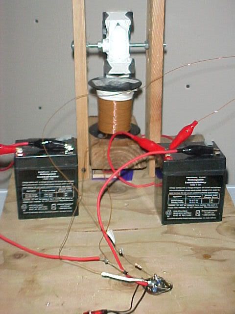
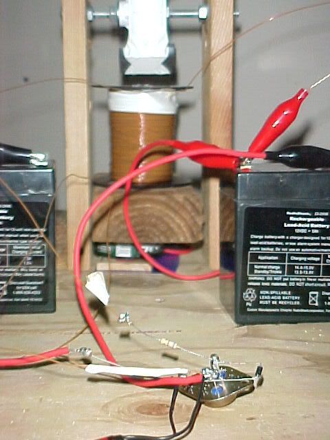
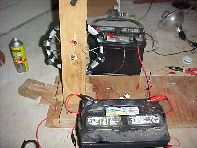
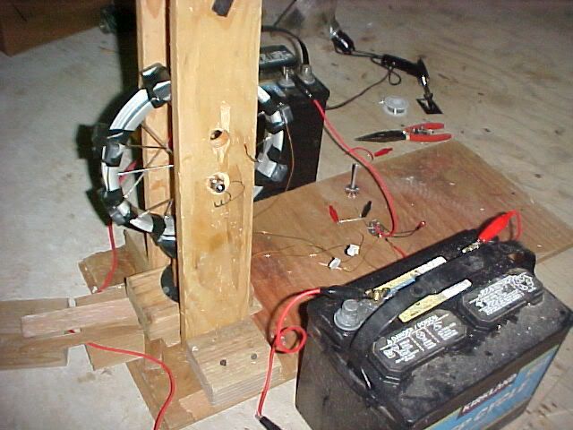
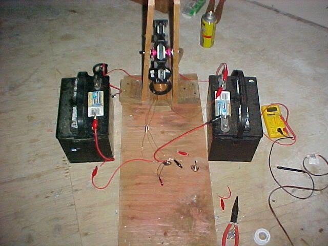
Here are some VERY EARLY and rough renditions of an SG....these were from November 2004 before I even started testing.
First two were gel radio shack 12 volt, the last 3 were walmart deep cycle...this was BEFORE I even moved the project to a bench and started really getting into it.
Announcement
Collapse
No announcement yet.
Bedini SG
Collapse
X
-
Originally posted by patmac View PostHi Kevin...
I'm testing a little Bedini, how do you think the best way to test efficient?
I was testing it, with 3 batts 9 volts, using two in series to get 18 volts and anotherone as charging batts, my results no has been so bad,
I've two days interchange it putting in target batt with lowest volts.
The three Batts last day have 8.20 to 8.50 volts.
What do you think??
Aaron, or one of the other more technically inclined persons here would be able to help you best on most accurate testing method.
As and aside-I only used 12 volt batteries. I did do some testing with 24 volts, but my results (COP-wise) were not as good as I got with 12 volts.
Leave a comment:
-
Originally posted by theremart View Post>http://www.energeticforum.com/renewa...choolgirl.html
>It is the basic SG with 2 circuits, double stacked magnets, a wire in the ground >going to the battery, and lots of work in tuning it to get the most charge.
Ok sorry I did not read your PM to me closer. Are you using a single coil for this? And can you give us a picture of your setup?
Thanks
I have looked for pictures and though I took dozens, have not found any yet. ....
I just took a break from this post and went and looked again. I found some pics of a few VERY early renditions. Will keep looking for the more recent (two circuit/single coil rendition).
Post will the pics and some TRV data will follow shortly.
oh, btw, Aaron may have some pics also...the only reason I ever took any pics was to send to him.
When we moved back to the mainland from Maui I did NOT bring my wheel. I did bring my circuitry and coil, and I just went and looked in the box they are in....it is a mess from not getting packed well from before shipping.
Leave a comment:
-
Originally posted by Kevin View Post
I have measured many different ways...gotta remember I am charging mostly deep cycle marine batteries, some of which are rated at 100 amp hours or more. I have a BK precision Battery Capacitance Analyzer for raw/rough readings.
To get an accurate "real world" reading I would run for 24 to 72 hours, periodically checking the rate of discharge of the source battery (making sure it was stable). This would give me the amp hours used to charge the other battery.
I would then discharge the charged battery with a consistent drain (light bulb or fan in an enclosed room) using an inverter with an alarm that would sound when it depleted the battery to a certain voltage level.
I am sure there are more accurate methods (and with smaller batteries those would Have to be employed), but when you are talking about using 20-40 amps for a test, and that test is a real world application, AND you do the tests hundreds of times, it was good enough for me.
btw, Aaron periodically has tried to correct my terminology, and explain how/why things are happening they way they do...I sorta just care about real world applications, like taking a battery that would NOT crank a truck no matter how many times it was charged conventionally, and then conditioning it with the SG and being able to use it in a truck again
Also, living in Hana, Maui for 3 years where the power grid is less than reliable I was dependent on battery/inverter pairings for daily uninterrupted power. Being able to use a SG conditioned and charged battery for 3-4 days without having to lug it 100 yards every 1-2 days (for a conventionally charged battery) was nice too.
Another thing I did was "round robin" the charging and discharging batteries for weeks on end, never having to use an outside charging source to supplement them, and they both just kept getting stronger. (this was AFTER they were fully conditioned).
Yeah, regarding the final wire...I am sure I could do better...I only have experimented with that a bit. 16 gauge multiple strand copper. I have tried heavier per some Bedini stuff I read. I think as much as 4 gauge....positive results plummeted.
Keeping the wires as straight as possible, all the same length, and as little crossing over each other seems to make a measurable difference.
Standard diodes...never even thought about multiple diodes.
I'm testing a little Bedini, how do you think the best way to test efficient?
I was testing it, with 3 batts 9 volts, using two in series to get 18 volts and anotherone as charging batts, my results no has been so bad,
I've two days interchange it putting in target batt with lowest volts.
The three Batts last day have 8.20 to 8.50 volts.
What do you think??
Leave a comment:
-
1.9 results
>http://www.energeticforum.com/renewa...choolgirl.html
>It is the basic SG with 2 circuits, double stacked magnets, a wire in the ground >going to the battery, and lots of work in tuning it to get the most charge.
Ok sorry I did not read your PM to me closer. Are you using a single coil for this? And can you give us a picture of your setup?
Thanks
Leave a comment:
-
Again thank you for your info! I can see why you depend on this method so much, you have to depend upon it!
Ok, I am using 200 amp hour batteries and I have 3 1000 amp hour batteries. ( semi batteries ) and they do take some getting used too. They started as sulfated, and slowly they seem to be getting better. I am speeding up the process of conditioning them by drawing more amps with my multi coil SSG. ( Pulling about 7 amps with the inverter )
So are you charging 3 batteries at a time? Or do you condition the batteries first then match them with impedence? in Series?
Your load test sounds very reasonable, pulling 1 amp? for 24 - 72 hours?
Yes if you can put 20 amps you have a REAL world test!...
Aaron does not even try to correct me I guess I am beyond hope he he
Using multi coil on your Bedini?
Grade of ceramic magnets 8? ( superpole configuration?)
Sorry for so many questions but I really want one of these babies !!!
So you use 16 gauge going on to the collector, 12 gauge on the rest?
Do you use an inverter for the primary battery?
I mentioned many diodes because I see some of the older schematics showing multi diodes, but in Aarons' video with the tape deck Aaron stated that the electricity only went thru one of them if I recall correctly .
Peace and THANKS for the tips.Last edited by theremart; 07-22-2008, 12:29 AM.
Leave a comment:
-
Originally posted by theremart View PostThanks for that info Kevin,
I have burnt up dozens myself, but all has been very stable since I have found a configuration that works for me.
Also I wanted to know your COP of 1.9. Was this measured in Joules?
What was the final wire you found worked best from the collector to the battery?
Are you using the standard diodes? or multiple diodes?
I have measured many different ways...gotta remember I am charging mostly deep cycle marine batteries, some of which are rated at 100 amp hours or more. I have a BK precision Battery Capacitance Analyzer for raw/rough readings.
To get an accurate "real world" reading I would run for 24 to 72 hours, periodically checking the rate of discharge of the source battery (making sure it was stable). This would give me the amp hours used to charge the other battery.
I would then discharge the charged battery with a consistent drain (light bulb or fan in an enclosed room) using an inverter with an alarm that would sound when it depleted the battery to a certain voltage level.
I am sure there are more accurate methods (and with smaller batteries those would Have to be employed), but when you are talking about using 20-40 amps for a test, and that test is a real world application, AND you do the tests hundreds of times, it was good enough for me.
btw, Aaron periodically has tried to correct my terminology, and explain how/why things are happening they way they do...I sorta just care about real world applications, like taking a battery that would NOT crank a truck no matter how many times it was charged conventionally, and then conditioning it with the SG and being able to use it in a truck again
Also, living in Hana, Maui for 3 years where the power grid is less than reliable I was dependent on battery/inverter pairings for daily uninterrupted power. Being able to use a SG conditioned and charged battery for 3-4 days without having to lug it 100 yards every 1-2 days (for a conventionally charged battery) was nice too.
Another thing I did was "round robin" the charging and discharging batteries for weeks on end, never having to use an outside charging source to supplement them, and they both just kept getting stronger. (this was AFTER they were fully conditioned).
Yeah, regarding the final wire...I am sure I could do better...I only have experimented with that a bit. 16 gauge multiple strand copper. I have tried heavier per some Bedini stuff I read. I think as much as 4 gauge....positive results plummeted.
Keeping the wires as straight as possible, all the same length, and as little crossing over each other seems to make a measurable difference.
Standard diodes...never even thought about multiple diodes.
Leave a comment:
-
RE: Transistor.
Originally posted by Kevin View PostI received a PM asking the following...thought I should post the answer here for anyone else interested.
"I was just wondering if you could tell me what transistors you are using on your SSG?"
For a long time I was using the 2N3055 Transistor, 100V, TO-3 case; fully metal
I then switched to the MJ2194. I do not know that I noticed any improvement.
The reason for the change was for easier replacement and mounting to a heat sink. (with all my experimentation I burned up dozens of transistors)
I have burnt up dozens myself, but all has been very stable since I have found a configuration that works for me.
Also I wanted to know your COP of 1.9. Was this measured in Joules?
What was the final wire you found worked best from the collector to the battery?
Are you using the standard diodes? or multiple diodes?
Leave a comment:
-
I received a PM asking the following...thought I should post the answer here for anyone else interested.
"I was just wondering if you could tell me what transistors you are using on your SSG?"
For a long time I was using the 2N3055 Transistor, 100V, TO-3 case; fully metal
I then switched to the MJ2194. I do not know that I noticed any improvement.
The reason for the change was for easier replacement and mounting to a heat sink. (with all my experimentation I burned up dozens of transistors)
Leave a comment:
-
n-filar coils??
Hi All,
I am about to get some more coils made and was wondering what peoples experiences with n-filar coils has been.
Is there are an optimal number?, can you have too many on one spool? Things like that.
I am planning to get quad-filar coils made, but if someone has had good results with a higher number I will give that a go.
Cheers,
Steve.
Leave a comment:
-
Originally posted by patmac View PostOoops, you can calculate the load for the transistor, depending of AWG power coil, and turns, is possible calculate wire lenght and with the wire lenght calculate ohm of the load, applying ohm law, you can get how much amps is loading transistor. If impendance is very low, transistor get burn by excesive amp drawing...
Other problem can be max volts to base - emitter, is possible that your trigger coil is working very very fine and can send a voltage higher than base - emitter 2n3055 can handle. But don't forget that Diode connected in (D1) Base - Emitter, is like a zener diode of 0.6 volts aprox. You can try limit current Colector with a Resistor between Coil and Colector. If you Back EMF is giving to you Back EMF very high voltage, you can reforce D2 with more diodes in series, remember that common diodes only control 1000 volts max, in series is 1000+1000 etc..
Thanks for your advice.....
I never calculate before......
about the series diodes as you said....what about if parallel as per schematic drawing? what the purpose they suggest 5 or more in parallel?
Hi All,
Please advice if you have other suggestion...
Selamatg
Leave a comment:
-
RE: 1 KW output
Originally posted by diehard_113 View PostDear All
Im very interested in Bedini SSG and want to buy it, im need 1KW to 2KW output
Please contact me: lvtrung@vnn.vn
What you are after would be something called a Monopole Energizer. And the only people that could set you up are are John Bedini or Rick.
Contact Rick at
Renaissance Charge LLC New Life for Batteries
He should be able to point you in the right direction.
PeaceLast edited by theremart; 07-17-2008, 02:29 PM.
Leave a comment:
-
Originally posted by diehard_113 View PostDear All
Im very interested in Bedini SSG and want to buy it, im need 1KW to 2KW output
Please contact me: lvtrung@vnn.vn
Cheers.
Leave a comment:
-
Dear All
Im very interested in Bedini SSG and want to buy it, im need 1KW to 2KW output
Please contact me: lvtrung@vnn.vn
Leave a comment:
-
Originally posted by selamatg View PostPatmac,
Currently my setup as the second option. The only problem with this the transistor so easy burn (2N3055) specially when first tuning.
Selamatg
Other problem can be max volts to base - emitter, is possible that your trigger coil is working very very fine and can send a voltage higher than base - emitter 2n3055 can handle. But don't forget that Diode connected in (D1) Base - Emitter, is like a zener diode of 0.6 volts aprox. You can try limit current Colector with a Resistor between Coil and Colector. If you Back EMF is giving to you Back EMF very high voltage, you can reforce D2 with more diodes in series, remember that common diodes only control 1000 volts max, in series is 1000+1000 etc..Attached FilesLast edited by patmac; 07-17-2008, 01:26 PM.
Leave a comment:
Leave a comment: