Announcement

Collapse
No announcement yet.

Bedini Capacitive Discharge Chargers

Collapse
X
 
  • Filter
  • Time
  • Show
Clear All
new posts

  • Originally posted by citfta View Post
    Hi geotron,

    My experience with that kind of circuit is not too good. What happened for me was when the cap got charged high enough to turn on the zener the zener just starts to turn on. This turns on the transistor but not fully on. The transistor conducts just enough to keep the cap at a level that just keeps the zener barely turned on and thus you reach a stable condition which is just charging the battery the same as without the pulsing circuit. I have been meaning to order some diacs. The diac has full on or full off kinda snap action. I think with a diac in series with the zener this would be a good circuit. I haven't tried that yet so I could be wrong about how well that would work.

    Later,
    Carroll
    citfta,

    In the past I've found much the same results as you've indicated with
    using Schottky diodes, although what I've not found yet is how the transistor
    or SCR would react when the potentiometer is such that it will only let through
    sufficient current to turn on the Base or Gate when the Schottky diode is fully
    open.

    Perhaps the voltage of the charging capacitor would pass through the
    potentiometer and meet with the Schottky until it is 90% open, and only
    then would there be sufficient current to open the transistor. ??

    Other than this, and the diac, there seems to be one other method
    utilizing an op-amp.

    [ The Schmitt Trigger ]

    [ Schmitt's Comparator Circuit ]

    [ Google Search - Schmitt Trigger ]
    Comment


    • Originally posted by FRC View Post
      I could have bought one of these 1 farad audio capacitors for $99.95 a couple
      months back. Does anyone know if that is a good price for one of those ?

      George
      That price is a little high.
      "Anything the mind can conceive and believe, it CAN achieve." Napoleon Hill

      Comment


      • Cap Pulser update

        Hi All,

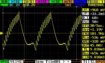
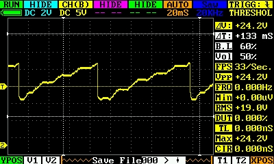
        I took the opportunity to put the cap pulser circuit on a scope and watch for a while. I have found that the circuit, as diagrammed, works properly. I changed the cap value to 1000mF @30V. I also changed to a 12.1V zener. I may fool with that a bit more. It works pretty well, giving a stairstepped sawtooth wave across the cap, but only on a reasonably good battery. See attached scopeshot. A battery in bad shape gives a waveform that looks like ringing spikes that only vary by a volt or so.


        Good battery:


        Not so good battery:


        Notice in particular the voltage scale of the two traces... 5V/div vs .2V/div!


        Enjoy,
        Twinbeard
        Last edited by twinbeard; 02-01-2012, 03:29 AM. Reason: add image
        "Anything the mind can conceive and believe, it CAN achieve." Napoleon Hill

        Comment


        • solar

          Originally posted by totoalas View Post
          Good job mate May I know the input current and maybe try with a solar as well???


          totoalas
          Hey Totalas,

          Forgot to speak on the solar. All of this is running from solar. I have 640W of panels charging a 1600Ah @12V battery bank. There is a 1F 20V cap paralleled with the battery bank. My benches are wired with 12V busses, which I run all of my experimental work on.

          So yes, it works well from solar I have another device I will be showing soon that is designed to be powered directly by a dedicated panel, eliminating the charge controller
          and battery bank in between, and a Uni-Solar PVL-68 to power it. Way too much power for what the device draws, however, but the smallest in Uni-Solar's line of flexible thin film panels. Perhaps one of their roofing tiles would be appropriate...
          In any case, the panel charges a big cap bank, which drives the device in the event of very low light conditions.

          Enjoy,
          Twinbeard
          "Anything the mind can conceive and believe, it CAN achieve." Napoleon Hill

          Comment


          • Originally posted by twinbeard View Post
            Hey Totalas,

            Forgot to speak on the solar. All of this is running from solar. I have 640W of panels charging a 1600Ah @12V battery bank. There is a 1F 20V cap paralleled with the battery bank. My benches are wired with 12V busses, which I run all of my experimental work on.

            So yes, it works well from solar I have another device I will be showing soon that is designed to be powered directly by a dedicated panel, eliminating the charge controller
            and battery bank in between, and a Uni-Solar PVL-68 to power it. Way too much power for what the device draws, however, but the smallest in Uni-Solar's line of flexible thin film panels. Perhaps one of their roofing tiles would be appropriate...
            In any case, the panel charges a big cap bank, which drives the device in the event of very low light conditions.

            Enjoy,
            Twinbeard
            Thanks Twinbeard
            Need all the devices I can build into my 12 v 7 ah battery ....for now ..until your next big one comes along lol

            happy experimenting

            totoalas

            Comment


            • cap pulser

              Originally posted by twinbeard View Post
              Hi All,

              I took the opportunity to put the cap pulser circuit on a scope and watch for a while. I have found that the circuit, as diagrammed, works properly. I changed the cap value to 1000mF @30V. I also changed to a 12.1V zener. I may fool with that a bit more. It works pretty well, giving a stairstepped sawtooth wave across the cap, but only on a reasonably good battery. See attached scopeshot. A battery in bad shape gives a waveform that looks like ringing spikes that only vary by a volt or so.


              Good battery:


              Not so good battery:


              Notice in particular the voltage scale of the two traces... 5V/div vs .2V/div!


              Enjoy,
              Twinbeard
              Which circuit are you refering to?

              Comment


              • Originally posted by Guruji View Post
                Which circuit are you refering to?
                I am referring to the scr/zener circuit I posted a schematic revision for in post #95 of this thread:

                http://www.energeticforum.com/renewa...tml#post176728

                I am considering adding the LED to the circuit for visible dump indicator, while moving the voltage down a bit on the zener. Currently I am using two 2000 microfarad 15V caps in series, and a 12.1V zener. It seems about the minimum value for the circuit, based on the waveform. Increasing cap values will lower dump frequency, as well as the current dumped across the battery. I paralleled in 3250 microfarads more last night, which had the dump frequency at about 2Hz.

                It makes me want to really fine tune this to highest frequency dump, and have the caps dump into the primary of a small exciter instead of a battery, and see what happens.

                Enjoy,
                Twinbeard
                "Anything the mind can conceive and believe, it CAN achieve." Napoleon Hill

                Comment


                • Cap Dump Video

                  Hi All,

                  I made a short video of the fan with the cap dumper circuit:
                  Cap Pulser Circuit - YouTube

                  Enjoy,
                  Twinbeard
                  Last edited by twinbeard; 02-03-2012, 08:34 AM.
                  "Anything the mind can conceive and believe, it CAN achieve." Napoleon Hill

                  Comment


                  • Hi guys

                    Just built a cap pulser, triggering the SCR with a neon light, the neon triggers the SCR once and then the SCR stays open,

                    I’m using a 1000uF flash cap 380v, dumping it to an old 150amp truck battery with 12.43v standing , cap charges in 1 sec, and neon discharges once and then stays open.

                    Any quick resolve for this? Will to get building a 555 timing circuit later.

                    Virus

                    Comment


                    • Hi Virus,

                      What do you mean by "stays open"? Do you mean the SCR burns out and no longer works? Or do you mean the SCR turns on and won't turn off? I am not really trying to pick on you but the term open or stays open is misused a lot on this forum. People who actually work in electronics only talk about an electronic device being open when they mean it has burned out and is open inside. Think of the old knife switch you used to see in the movies. When the blade of the switch is up the switch is open. When you put the blade down you close the switch and complete the circuit. Electronic devices turn on and off, they do not open and close.

                      In your circuit if the SCR is staying on after first turning on it is probably because there is still current flowing from the cap into the battery. SCR's will not turn off if there is still current flowing through them. You have to design your circuit so the cap will discharge to the point where no current can flow into the battery in order for the SCR to turn off and wait for the neon to fire again. Unless you have a pretty slow charge rate on the cap it is very difficult to get it to work with only a neon and SCR. You might try increasing the size of your cap and see if that helps.

                      Respectfully,
                      Carroll
                      Just because someone disagrees with you does NOT make them your enemy. We can disagree without attacking someone.

                      Comment


                      • Hi Carroll thanks for getting back to me and thank you for your time !

                        As you can see I am closed (don’t know), seems like you are open (can help) ! (got it !)

                        Sorry, I just tinker with electronics and not to snappy with all the terms etc. as you have noticed,

                        Yes, that is what is happening, the SCR stays open and I can see the battery volts still climbing after the first trigger, on 1 ste charging the cap it draws 1.8 amps, after the first trigger the amps drops back to 1.0 amp. and stays there.

                        I have tried a 3300uF cap takes a little bit longer to charge but the SCR still stays open after the first trigger.

                        I have 7 of those 3300uF caps, maybe I should hook them up in parallel? That will take longer to charge BUT don’t think that the SCR will handel the discharge?

                        Is it safe to assume that a 555 circuit to trigger the SCR in this case will still not close because of the current that is still flowing? If the 555 circuit closes the SCR, it will still stay open because of the current flow?

                        What device will close even thou there are still current flowing, think my coil is charging quite fast?

                        Thanks

                        Virus

                        Comment


                        • at 150 amp SCR still open

                          Hi me again

                          I tuned the system to 150 mA, takes about 4 seconds to charge the cap, the neon triggers the SCR, and the SCR still stays open, how can I get the SCR to close?

                          Virus
                          Last edited by Virus; 09-17-2012, 02:49 PM.

                          Comment


                          • Originally posted by twinbeard View Post
                            Hi All,

                            I took the opportunity to put the cap pulser circuit on a scope and watch for a while. I have found that the circuit, as diagrammed, works properly. I changed the cap value to 1000mF @30V. I also changed to a 12.1V zener. I may fool with that a bit more. It works pretty well, giving a stairstepped sawtooth wave across the cap, but only on a reasonably good battery. See attached scopeshot. A battery in bad shape gives a waveform that looks like ringing spikes that only vary by a volt or so.


                            Good battery:


                            Not so good battery:


                            Notice in particular the voltage scale of the two traces... 5V/div vs .2V/div!


                            Enjoy,
                            Twinbeard
                            Hi Twinbeard,

                            I am curious about the not so good battery producing such a different result with the pulse circuit. Is this because most of the spike is being absorbed by the battery or what? Do your neons fire when this is going on? (I've seen my neons fire when a not so good battery is connected. I think because the battery isn't capable of absorbing the spike since it is bad.)

                            Thanks,
                            Chris

                            Comment


                            • Hello everyone

                              Can someone pls post circuit of the cap dump with relay instead of scr ?

                              I have tried several times with different way of connecting the relay .. but seems I am missing something.

                              Thanks.

                              Comment


                              • relay cap dump

                                Originally posted by cdjambov View Post
                                Hello everyone

                                Can someone pls post circuit of the cap dump with relay instead of scr ?

                                I have tried several times with different way of connecting the relay .. but seems I am missing something.

                                Thanks.
                                This isn't the full schematic but this could accomplish it - this was for cap dump to an ignition coil:


                                You need a dpdt relay and connect cap to common and NC - NC would be from the SG or SSG output. Then you need something to trigger the relay coil by either time or cap voltage. Triggering coil will disconnect cap from SG and then dump to battery instead of ignition coil like you see in the diagram.

                                Is there a reason you want to use a relay instead of an SCR?
                                Sincerely,
                                Aaron Murakami

                                Books & Videos https://emediapress.com
                                Conference http://energyscienceconference.com
                                RPX & MWO http://vril.io

                                Comment

                                Working...
                                X