Announcement

Collapse
No announcement yet.

One magnet no bearing Bedini motor

Collapse
X
 
  • Filter
  • Time
  • Show
Clear All
new posts

  • "Magnet On A Leash"---Great idea Mart!! It works!!!

    @Mart & All
    I replicated Mart's "Magnet On A Leash" and was amazed at how well it works. It such a simple idea. It used my little pulse motor 'Turner' to demonstrate the idea in this video.
    YouTube - Magnet On A Leash---Mart's great idea.ASF

    Good job Mart.

    Lid

    Comment


    • @theremart.Hi Mart.I did not realise you were using two transistors in your circuit, i think that's a first tooIf you get a chance,can you post the circuit as you have a good charging setup there and i am sure there are others who may want to try it.
      I myself have not done any real charging tests and with my focus with these motors being on running at low voltage and usually use a 9v battery as a charge battery so you have much more experience on the charging as i know you have put a lot of time a effort into this aspect from your past experiments but what i can say is i am pretty sure the charge rate decreases with reduced current draw so like you said,you have to strike a ballance.
      Regarding your torch,What type of magnet is inside,is it diametrically magnetised?Anyway great work Mart.regards jonny
      @Lidmotor.Nice job on Marts motor.I am sure the friction could be reduced with the resulting increase in performance and then this could be a very useable device with many uses as it it as mart said,fully controlled and this means we can get work from the magnet without sending it bannanas
      You mentioned that you could not get the magnet in your torch to spin,is it possible to open the torch up and swap the magnet for one of your cylinder magnets and see if that works as this could be the perfect prebuilt satellite.Great work as usual. regards jonny.

      Comment


      • Good work with the 2 transistors Mart. I have used 3 transistors with a quadfilar coil for mine. But i have been using a 12V lead-acid car battery. I havent used it in a little while so I cant remember how much current it uses. And its hard to keep up with everyone since this thread is so versatile.
        My one magnet is on a shaft of carbon fiber with bearings on the end. (not really a no bearing like the origin of this thread why i didnt post more about it.) I tried to make a kind of airbearing, like johnny did, but failed miserably.
        I can move the neo to any position around the coil once it starts up. Actually the fastest is to the side of the windings and the strongest is virtually right in the hole for the aircore. I can produce a decent amount of torque with this method, but I think i still need more. I can apply a decent amount of pressure with my finger and it wont stop at least.
        Once I get my funds back in order I will get more magnet wire. my carbon fiber shaft is 3 feet long. My plan is to place a total of four magnets evenly spaced on shaft being pushed by at least 2 but im shooting for three quad coils each. I was thinking 2 magnets out of phase from the other 2, along with a mass for flywheel, to produce torque. One set on when the other is off. Then place a gear on end of shaft like Lidmotor has done with his. (at least I think thats a gear on Turner)

        Comment


        • RE: circuit..

          All I am using is the Monopole setup

          http://www.energeticforum.com/renewa...energizer.html

          ( with trigger and two power coils ) Twisted wire.

          But, I use different transistors.

          1. I use the cheap transistors that Erin uses -->

          BD243C

          Erwin's Work Shop.


          Right now I am running a test of charging 2 12 amp hour batteries at the same time. I am pulling 1 amp current but the transistors is only slightly warm to touch. I find it interesting when I look at the scope the Hump on the h way is very straight out. It is giving a decent charge rate.

          Another thing I noticed to day is it is very hard to find the right wire that will spin freely with the magnet. The one that worked best for me is one that has a shiny plastic coating. I also found that the neo will sometimes stick to certain wires..

          I attempted to find a way to use VCR bearings today, came very close as I found a brass rod that will fit inside the neo very nicely however it was not small enough to fit inside the vcr bearings I considered grinding it down so it would but without a machine shop I am afraid it would be a bad idea.

          Anyhow, I have plenty of other projects competing for my vacation time, but this sure has made my vacation fun!

          Thanks for Lidmotor for the promo campaign
          See my experiments here...
          http://www.youtube.com/marthale7

          You do not have to prove something for it to be true. However, you do have to prove something for others to believe it true.

          Comment


          • Wirey Coyote

            " I attempted to find a way to use VCR bearings today, came very close as I found a brass rod that will fit inside the neo very nicely however it was not small enough to fit inside the vcr bearings I considered grinding it down so it would but without a machine shop I am afraid it would be a bad idea."

            Brass machines very well, so you may want to try putting your brass rod in an electric drill and squeezing a bit of sandpaper against it (or a file if you have one) and you will soon take it down to what you need.

            You may also want to try a piece of house wire that has the insulation removed, or the bare ground wire of the house wire strand. It is a nice guage to bend at right angles and it will hold its shape well. Might cause a bit of lenz drag, but then again, you may just put a meter on each end of it and see if you are getting any power out. Come to think of it, why not bend that wire right around the magnet a few times and you now have a generator. Or better yet, bned the wire around the magnet and also around a toroid so you have 1/2 a joule thief ready to go directly from your newly built integrated generator... (things that make you go hmmm.)
            When you pick up a cat by the tail you learn things you cannot learn any other way...

            Comment


            • @Redrichie.Please feel free to post details of your motor here as your using diametrically magnetised magnets so it will fit right in here.That goes for anyone else too. If your still want to levitate your rotor i can help there.I have done a bit more work on mine and added a 2nd layer of magnets which has the effect of pushing the rotor in the opposite direction making it almost neutral so now it is only touching one point with minimal friction and sometimes non but it is still a work in progress so it may be worth another go as it sounds like you have big plans for your motor. Regards jonny.

              Comment


              • At last... magnet on bearing.

                Got the magnet working on a VCR bearing.

                YouTube - Video 79 Jonny's magnet now on a VCR bearing.wmv

                Charge rate is decent.

                The next part is I would like is ThaneCHeins method of extracting from coils and speeding up the rotation. Tried 2 transformers but no sucess on that I guess he has a custom setup...
                See my experiments here...
                http://www.youtube.com/marthale7

                You do not have to prove something for it to be true. However, you do have to prove something for others to believe it true.

                Comment


                • Correction.... only 15,000 RPM not 23,000 RPM

                  I got some advice that the reason my tach was having trouble getting a reading was because the magnet was so reflective.

                  YouTube - Video 80 Correction, NOT 23,900 RPM.wmv

                  That being said I am happy that my VCR bearing setup reaches a true 18,000 RPM at 34V.

                  Mart
                  See my experiments here...
                  http://www.youtube.com/marthale7

                  You do not have to prove something for it to be true. However, you do have to prove something for others to believe it true.

                  Comment


                  • Magnet on wire.

                    This is really fantastic. El tigre's right! Steve Mark's TPU patent states that his generator consists of ring magnets with a wire through the hole in the first sentence of his disclosure. Marks first prototype had a Reed switch and he started his TPU with a magnet. His last video shows him demonstrating gyroscopic inertial force. I believe he was either spinning the ring magnets or pulseing them to oscillate. The wire has to be generating current as El tigre points out. It might be possible to wrap a secondary right around the wire. The other observation I made was that a capacitor of equal impedence to the power coil, wired either in series for voltage, or parallel for current between the power coil and Reed switch, creates a Hartly tank resonant feedback circuit that cuts input by fifty percent. The circuit needs a variable capacitor, which is more commonly recognized as a radio tuner, in series between the power coil and Reed switch. The capacitence can not be greater or less. Too large a capacitor delays the return of the collected pulse to the coil, and too small creates hysterisis. A power control potentiometer needs a tuner with a knob to adjust the feedback capacity to coil resonance. The inclusion of this Hartly resonant feedback cap, actually an amplifier with gain of fifty percent, cuts input current by that amount. I believe Steve Mark had just such an amplifier on the primary pulse coil that wraped around the stacks of ring magnets with the wire through the hole in the center, and that he oscillated them, one stack reversed in polarity from the other. Four north up and four north down. El tigre went a step further with his idea of wrapping a Joule Thief from the magnet wire axle. Great idea! Here's another: Levitate the tube magnet over an opposed pole set of ring magnets, one glued to the bottem of the tube with an insulator spacer, and the other set on a tiny table platform to create a frictionless bearing. The wire's the output loop. The potentiometer knob regulates the power to the pulse coil, and the tuner knob the capacitence of the variable capacitor to tune tank resonance. The wire can loop in and out of let's say eight spinning magnets driven by the same pulse, perhaps with a secondary wraped around the bridge sections. I believe this would amount to an improvement of Marks TPU, as his generator heated up, probably from friction of the oscillating rings over his internal wire. I hope Lidmotor can wire a tuner on Turner! Excellent work Ladies and gentelmen, you folks really help fire my imagination!
                    Last edited by synchro; 12-02-2009, 05:21 PM. Reason: correction

                    Comment


                    • Light Multiplier

                      @ All
                      I made a magnet spinner out of a microwave exhaust fan motor coil using a very simple one AA battery-- 2N2222 circuit. The circuit is like an JT circuit as it uses a center tap coil arrangement. It lights up three LEDs---one on the 5khz driver circuit and the neo spinner drives 'Maggie's' other two. The draw is about 20mA with or without Maggie. I call it the "Light Multiplier" because you get three for the price of one.
                      YouTube - Light Multiplier.ASF

                      Lidmotor

                      Comment


                      • @Lidmotor.BEA-utiful.If you are not seeing increased current draw from spinning the magnet and adding maggie then you may have a breakthrough here.Don't forget,you can also convert the light from the leds so that needs factoring in as well and have you considered trying to spin another magnet on the other end of the coil and double your output?
                        I have one off those microwave coils and i tried it on a bedini a while ago by adding another post imotep style but did not have much luck with it so i may resurect it now i have seen what it can do
                        I had one of those dreams last night about combining the one mag bedini with Dr Stifflers sec as we need a fast switching circuit and the Bedini circuit is probably not fast enough when triggered by the magnet but if your circuit is running at 5khz then i think it may work.Something else to try . Regards jonny.

                        Comment


                        • Hello all,

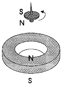
                          Did one of you ever tried to levitate the spinning magnet, by putting a magnet ring in the hollow coil core?

                          Something like this:


                          Edit: Added Background http://www.roddriver.com/science_990922.html


                          Keep up the good work
                          Last edited by Cherryman; 12-04-2009, 09:10 AM.

                          Comment


                          • @Cherryman.Thankyou for posting this.I found the background behind this idea very interesting.To my knowledge this has not been tried but can imagine it being a real headbanger to get going judging by that article.Thanks.Jonny.
                            @Lidmotor.Hi. I replicated your light multipier but it was to dark to make a vid,i will try to make one this week when i have some free time and have had a bit of a play with it.I just have the motor up and running but its great to have a new toy to play with.I am so glad i didn't chuck that microwave coil,must have been my soldering jeeeez.Here is a pic.The meter is measuring mv accross a one ohm resisitor.Regards jonny.

                            Comment


                            • Light magnifier.

                              Lidmotor has a center tap microwave fan coil resonating at 5khz spinning a tube magnet. Lidmotor claims the coil does not draw more power when the magnet spinner is placed nearby. This is really a VLF ham radio broadcasting antenna, and the magnet spinner is driven by radio waves. Ohm's law demonstrates that when resistence drops to zero, power reaches infinity. This is why we can operate our Rover on the surface of Mars. The magnet is capturing and transforming a full sine wave into kinetic energy that would otherwise just pass right through anything else. A crystal headset does the same thing, by cutting the full sine wave in half in the crystal diode, generating an electric current that is transformed into kinetic energy in the head phone speaker to produce sound vibration. My point is and has been in my former posts, that an increase in the number of radio recievers does not increase the draw in the broadcasting antenna, and the number of magnet spinners should not increase the draw by Lidmotor's center tap coil. The magnet is acting as a diode and transforming radio frequency power into the equivilent of electric current and kinetic energy. A magic bit of alchemy. Tesla's spinning egg was alledged to have made a horrific noise, as he spun it up to sub sonic speed producing shock wave from RF resonace in his power coils. He was quoted as saying this effect held the greatest promise for power from resonance, that's why he featured it at the World's Fair Exposition. The major diference is, it cost Tesla a fortune to manufacture the device Lidmotor has designed for a tiny fraction of the cost.

                              Comment


                              • Light magnifier study

                                Originally posted by jonnydavro View Post
                                @Cherryman.Thankyou for posting this.I found the background behind this idea very interesting.To my knowledge this has not been tried but can imagine it being a real headbanger to get going judging by that article.Thanks.Jonny.
                                @Lidmotor.Hi. I replicated your light multipier but it was to dark to make a vid,i will try to make one this week when i have some free time and have had a bit of a play with it.I just have the motor up and running but its great to have a new toy to play with.I am so glad i didn't chuck that microwave coil,must have been my soldering jeeeez.Here is a pic.The meter is measuring mv accross a one ohm resisitor.Regards jonny.

                                @Jonny---I'm glad to see that the coil you had worked. I experimented with mine yesterday and tried several different rotor arrangements. I'm still scratching my head trying to figure out what is really going on.

                                @Synchro----Now you really have me wondering about this. The spinning rotor is firing the transistor like in a normal pulse motor arrangement BUT---if you get the spinning rotor to go into an orbit around the mirror, the oscillator fades in and out of different frequencies (the oscillator light stays on and lights brighter or dimmer). There might be compound wave forms in action here. Maybe even "freak" waves that are pushing things along.
                                All I know right now is that "Maggie" likes it.

                                Lidmotor

                                Lidmotor

                                Comment

                                Working...
                                X