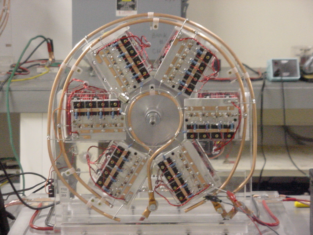
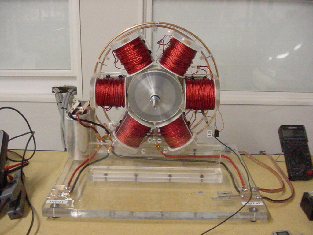
I hope the upload of the PIC's works as it will save me a lot of description of my issue. First a big thanks to John Bedini, Ron Pugh and Patrick Kelly as well as all of the new generation of inventors here.
Now to my problem, I have to eliminate all base resistance in my bias circuit for the MJL21194's to get enough current flowing to maintain rotation. My coils are wound exactly to the specs in Patrick's "Chapter 6.pdf", 120ft of 18awg. Litz wound 5 conductor. I had to also add additional length on my trigger coil and feel that I need to add more. Can someone tell me what the most optimum "number of turns" are necessary for the trigger circuit. Today I am achieving about 4 to 5 volts in the trigger circuit when the RPM is about 900-1000. My drive coils are pulling about 8 amps (Vcc 12.85, coil resistance 0.8) at this RPM which is most undesirable. On a positive note, it is charging like gangbusters. Hope this gives enough info. All help is appreciated.
Now to my problem, I have to eliminate all base resistance in my bias circuit for the MJL21194's to get enough current flowing to maintain rotation. My coils are wound exactly to the specs in Patrick's "Chapter 6.pdf", 120ft of 18awg. Litz wound 5 conductor. I had to also add additional length on my trigger coil and feel that I need to add more. Can someone tell me what the most optimum "number of turns" are necessary for the trigger circuit. Today I am achieving about 4 to 5 volts in the trigger circuit when the RPM is about 900-1000. My drive coils are pulling about 8 amps (Vcc 12.85, coil resistance 0.8) at this RPM which is most undesirable. On a positive note, it is charging like gangbusters. Hope this gives enough info. All help is appreciated.


Comment