Dear DIVERFUN ,
Sorry to chime in, I think the problem with understanding Fig. 24-3 from your old Electronics Basics book is that the + and - signs shown in it indicate voltage polarities and not current polarities, right? Just consider the coil as a generator with the indicated output voltage polarities as shown in Figure b (when the 8V battery is off).
If you accept this, then the understanding of the current flow direction will be clear in any coil: when the input current is switched off, field collapses but tries to maintain the original current but due to losses it is not able to (the amplitude of the spike starts decreasing) so the original current starts decreasing in value towards zero (it might change direction after reaching the zero value but this depends on the load across the coil (damping) whether it allows ringing as member citfta referred to).
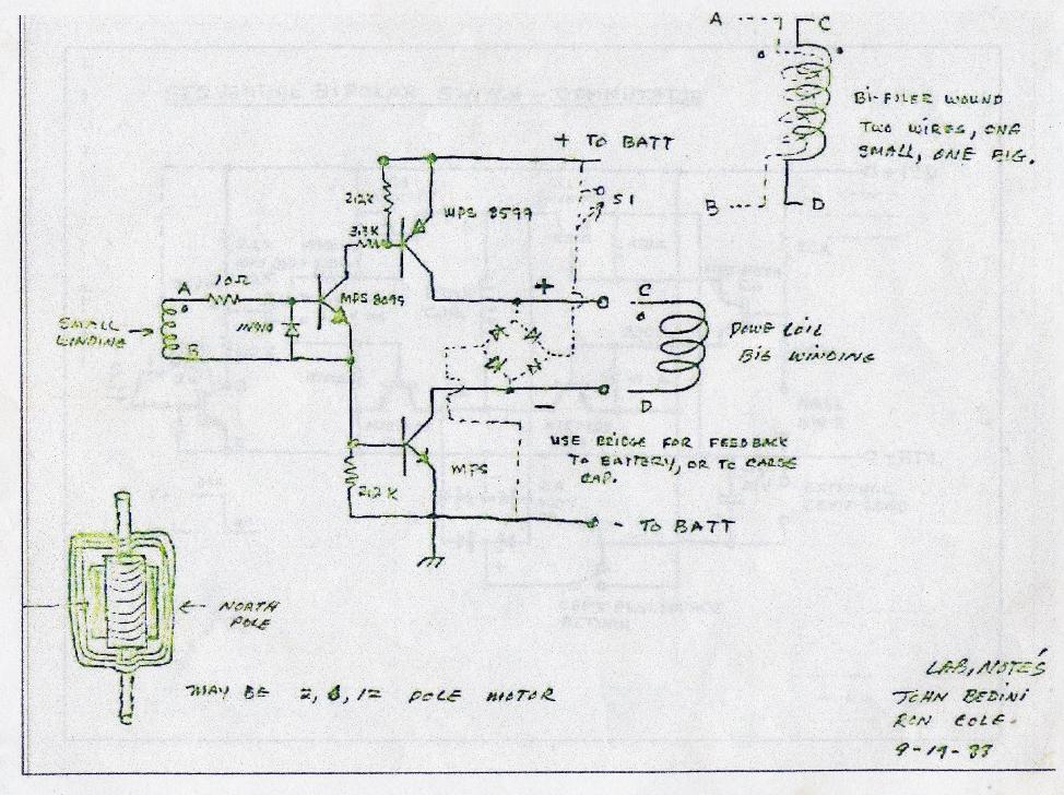
This also means that in your very first schematic (in your Reply #41) the big coil (L1) still has no discharge path via diodes D2 and D3, UNLESS the winding sense of L3 (the third coil) which is inductively coupled to L1 allowes current flow into capacitor C1 via D4 from the induced spike, okay?
I notice this because the voltage spike across coil L1 (when Q2 and Q3 are just switched OFF) will have a positive polarity at the collector of Q3 and a negative polarity at the collector of Q2. Your diodes D2 and D3 will block both these voltage polarities as they are drawn, preventing any current flow out of the coil L1. (One more notice: you would have to have a voltage difference first to cause any current flow in a closed circuit.)
Putting all this otherwise: when you connect a battery across a coil with a given polarity and then you disconnect it, the coil will behave also as a kind of 'battery' (giving out the voltage spike for a short amount of time) but would have an opposite polarity across its terminals with respect to what the battery forced onto it first. When you understand this, all the current flow directions (after the switch-off) will fall in place correctly.
rgds, Gyula

 Unity is good for me.
 and how your job way back took you


Comment