Announcement

Collapse
No announcement yet.

Bedini-Cole Window Motor Electric motor runs without draining batteries!!!

Collapse
X
 
  • Filter
  • Time
  • Show
Clear All
new posts

  • #61
    Collecting the Data


    Originally posted by Aaron
    Aaron Murakami

    here it is from: http://www.energeticforum.com/john-b...tteries-2.html

    @all, this is what I posted way back on Energetic Forum in Feb 22, 2007:

    Bedini-Cole Window Motor Electric motor runs without draining batteries!!!
    Hi everyone,

    One of my passions is studying and building "free energy" technologies.
    There are many misconceptions about this field and it is attacked by
    people claiming anyone doing anything in this field are a bunch of
    perpetual motion nuts.

    The truth is that these technologies are very real and they also have
    absolutely nothing to do with perpetual motion! I'm not getting into
    the specifics in this message about the distinctions because this topic
    is too important to focus on the misconceptions. Instead, lets shine some
    light on an amazing recent release.

    John Bedini is a world famous electrical engineer and is considered a
    "Mozart" with electronics and especially in the field of audio components
    because he builds he highest quality most crisp sounding audio amplifiers
    known to man.

    Besides the audio field, he also happens to be one of leading super
    geniuses in the field of electromagnetic energizers and "radiant energy"
    in general.

    For over 11 years, he had many plans posted on his website for many
    different versions of his motors and the "School Girl" motor is probably
    the most popular and there are thousands around the world building
    this motor achieving very exciting results that are supposed to be
    impossible.

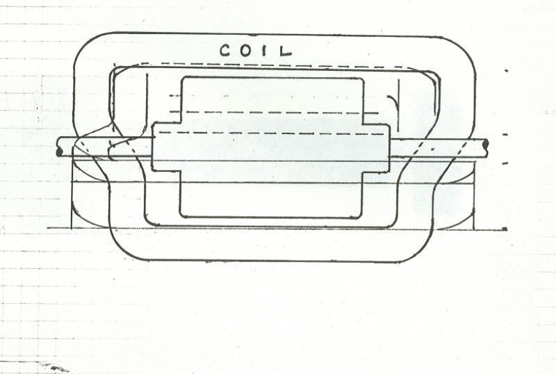
    Besides this motor, there is one version called a "Bedini-Cole Window Motor"

    This is what it looks like:


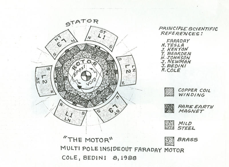
    The plans have been given out to the world on this website:
    MOTOR DIAGRAMS AND LAB NOTES

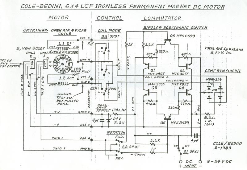
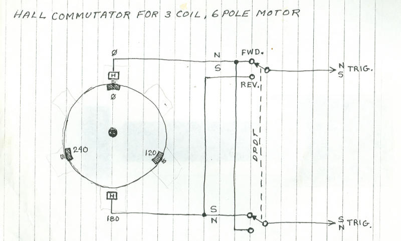
    The schematics for this motor are here:


    Watch a demo video: The page cannot be found this is 12MB's long
    so be patient or right click on the link and SAVE TARGET AS

    You can visit John's homepage here: Welcome to John Bedini

    Be careful not to miss any links because they are scattered and
    hidded all over his websites. There are many.

    One time at John's shop, he hooked up a little battery to this motor
    and it was so efficient it almost didn't register any amperage on the
    meter while it was running. Also, I grabbed the shaft with my hand
    and I couldn't even stop it!! It produces more torque for the least amount
    of power out of any motor that I think has ever been released.

    Anyway, Mike, an experimenter who did a small modification to the original
    plans wound up with a more efficient Window Motor that runs itself and
    keeps charging a capacitor charging up!

    Here is what his looks like:


    Here are the schematics / plans with the small modification:


    Watch this video:

    YouTube

    How does it power itself???

    That will be another discussion...but pass the link to this forum to your friends so we can
    get the word out. I'm not just someone excited about this...I have built many, many Bedini
    circuits and they all work as long as I build them according to his plans and not how I think
    they should be built. I'll post a thread later with a very simple motor that beginners can get
    their feet wet with..very simple stuff...a 10 year old girl built one so you can too!

    Aaron Murakami

    Comment


    • #62
      Past data collecting, sweet deal Thanks Aaron.


      Originally posted by Aaron
      Aaron Murakami

      Analysis by John Bedini PART 2
      Now read the story this way now in red, You will see how everything gets confused by all the posts in between. This is something I learned in the military, how to get the answers. I did change the Neo magnets out in my motor and it does make a big difference, "so no neos" in this one please. Get the facts straight and you will build this motor. Focus on what Mike said or "Fail" . Do not assume anything , Mike is thinking out of the box, Neo Magnets suck in this motor, trigger circuit now works fine in my set up, Next the SS solid state switch.
      John

      <O
      The hall effect transistor is to activate sw1 I use a solid state relay for sw1 wind as much turns as possible try to get above 6 ohm. The circuit will need a battery for power source.. Their are some modifications needed for acheiving unity, then you can get rid of the battery. Dont worry about that for now just get it to run with a battery<O</O
      Yes feedback, and play with sw1 timing I must tell you I use the third winding on my stator coil as a generator winding to charge the cap up from 0v, then when the transistors begin to pulse the back emf through sw1 brings the voltage on the cap even higher till it levels and the motor is then runing at unity
      <O</O
      <O</O
      I don't Know how long the motor can run for, but I always stop it after a few hours or so.<O</O
      I have come up with a diagram of the modification. and a close call, I had found the motor would not run after a couple wires were swiched around by accident. coil polarity is very important. yes same as Bedini/Cole.All components are the same except for the added parts a hall IC and a ss relay and also third winding. <O</O
      Main winding is connected at the collectors. follow Bedini/Cole cct great work.<O</O
      you must get your window motor running,then we can talk about charge timing and unity<O</O
      When you go to run your motor have a AM radio close to the stator coil you should here two cracks brodcasted for every magnet pair passing. a quick way to tell if you are hooked up correctly.<O</O
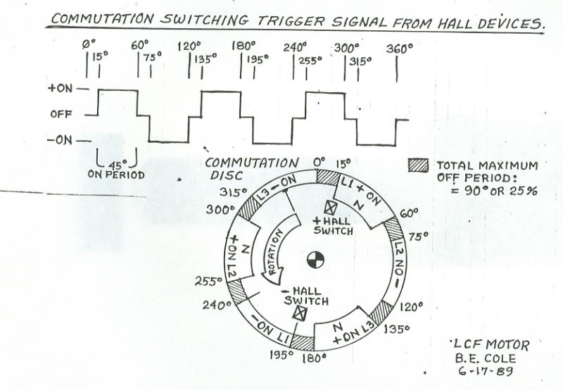
      I learned alot from these illustrations, look at the commutator to see the timing <O</O
      I think the third winding is allways charging the cap the ss relay puts the main winding in series with the third winding at the correct time, take into account the rectifier diode in between them. <O</O
      This is not overunity, just a motor that can charge a cap and run off it for a wile. <O</O
      I don't know if all is needed for the circuit.I just know that this is how I got it to run longer. how long I dont know so far maby a couple hours. I belive it is working at or near unity.<O</O
      Oh and the scope shots, the third winding shot scope is set to diffrent scope timing<O</O
      I know that the third winding charges the cap. and I think somthing coming through the ss relay helps this charge.<O</O
      I just want to say that I have never claimed this to be overunity I think it is near unity the third winding charges the cap quickly and the motor runs of this charge for a long time not forever.<O</O
      what I did after getting my motor to run without any mods.<O</O
      I would use it to charge a second battery hopeing I could switch the batteries over and over and it would run for ever, this was not the case, then I found out that if I charged a large cap up with it the motor drew less current from the battery. this was with sw1 between cap+ and bat+,,monitor your input current with diffrent caps to see what works best.<O</O
      -------------------------------------------------<O</O
      Now read it this way.<O</O
      John<O</O
      <O</O
      <O</O

      The hall effect transistor is to activate sw1 I use a solid state relay for sw1 wind as much turns as possible try to get above 6 ohm. The circuit will need a battery for power source.. Their are some modifications needed for acheiving unity, then you can get rid of the battery. Dont worry about that for now just get it to run with a battery<O</O
      Yes feedback, and play with sw1 timing I must tell you I use the third winding on my stator coil as a generator winding to charge the cap up from 0v, then when the transistors begin to pulse the back emf through sw1 brings the voltage on the cap even higher till it levels and the motor is then runing at unity<O</O
      I don't Know how long the motor can run for, but I always stop it after a few hours or so.I have come up with a diagram of the modification. and a close call, I had found the motor would not run after a couple wires were swiched around by accident. coil polarity is very important. yes same as Bedini/Cole.All components are the same except for the added parts a hall IC and a ss relay and also third winding. Main winding is connected at the collectors. follow Bedini/Cole cct great work.<O</O
      you must get your window motor running,then we can talk about charge timing and unityWhen you go to run your motor have a AM radio close to the stator coil you should here two cracks brodcasted for every magnet pair passing. a quick way to tell if you are hooked up correctly.<O</O
      I learned alot from these illustrations, I think look at the commutator to see the timing the third winding is allways charging the cap the ss relay puts the main winding in series with the third winding at the correct time, take into account the rectifier diode in between them. This is not overunity, just a motor that can charge a cap and run off it for a wile. <O</O
      I don't know if all is needed for the circuit.I just know that this is how I got it to run longer. how long I dont know so far maby a couple hours. I belive it is working at or near unity.Oh and the scope shots, the third winding shot scope is set to diffrent scope timing.<O</O
      I know that the third winding charges the cap. and I think somthing coming through the ss relay helps this charge.<O</O
      I just want to say that I have never claimed this to be overunity I think it is near unity the third winding charges the cap quickly and the motor runs of this charge for a long time not forever.<O</O
      what I did after getting my motor to run without any mods.<O</O
      I would use it to charge a second battery hopeing I could switch the batteries over and over and it would run for ever, this was not the case, then I found out that if I charged a large cap up with it the motor drew less current from the battery. this was with sw1 between cap+ and bat+,,monitor your input current with diffrent caps to see what works best.<O</O

      Aaron Murakami

      Comment


      • #63
        Right from the horses mouth

        Thx john you are the greatest. I'll take note.

        Everybody is gonna think I'm butterin you up

        I don't care what people say, your it. Oh and those who

        keep it all going.


        If I could get these other people ta stop

        hagglin over trifles we might get this show on the road.


        Originally posted by Aaron

        Analysis by John Bedini PART 3

        Analysis by John Bedini PART 3

        Now read the story this way,
        <o</o
        The hall effect transistor is to activate sw1 I use a solid state relay for sw1 The circuit will need a battery for power source.. Their are some modifications needed for acheiving unity, then you can get rid of the battery Yes feedback, and play with sw1 timing I must tell you I use the third winding on my stator coil as a generator winding to charge the cap up from 0v, then when the transistors begin to pulse the back emf through sw1 brings the voltage on the cap even higher till it levels and the motor is then runing at unity,but I always stop it after a few hours or so. look at the commutator to see the timing ,("""ss relay puts the main winding in series with the third winding at the correct time, take into account the rectifier diode in between them""".) I don't know if all is needed for the circuit.I just know that this is how I got it to run longer. how long I dont know so far maby a couple hours. I belive it is working at or near unity. I know that the third winding charges the cap.("" and I think somthing coming through the ss relay helps this charge"").what I did after getting my motor to run without any mods.<o</o
        I would use it to charge a second battery hopeing I could switch the batteries over and over and it would run for ever, this was not the case, then I found out that if I charged a large cap up with it the motor drew less current from the battery. this was with sw1 between cap+ and bat+,,monitor your input current with diffrent caps to see what works best.<o</o
        -------------------------------------------------------
        Now read the story this way, Do you all get it now.<o</o
        John
        The hall effect transistor is to activate sw1 I use a solid state relay for sw1 Yes feedback, and play with sw1 timing I must tell you I use the third winding on my stator coil as a generator winding to charge the cap up from 0v, then when the transistors begin to pulse the back emf through sw1 brings the voltage on the cap even higher till it levels..ss relay puts the main winding in series with the third winding at the correct time, take into account the rectifier diode in between them. I belive it is working at or near unity.I know that the third winding charges the cap.("" and I think somthing coming through the ss relay helps this charge"").what I did after getting my motor to run without any mods.
        The answer.
        ss relay puts the main winding in series with the third winding at the correct time, take into account the rectifier diode in between them. I belive it is working at or near unity.I know that the third winding charges the cap.("" and I think somthing coming through the ss relay helps this charge)<o</o

        Last edited by John_Bedini; Today at 05:32 PM.

        Comment


        • #64
          Compilation data collection so we can build this motor

          once and for all. Peter, when are you going to do a zero

          motor? Oops off topic. We'll gitcha later


          Originally posted by Peter Lindemann

          Comments by Peter Lindemann

          Comments by Peter Lindemann
          COMMENT BY PETER LINDEMANN of www.free-energy.ws<o></o>
          OK Everybody,<o></o>
          <o></o>
          John has explained the method Mike used to get his unit working, in Mike?s own words. Also, he has run the experiment and determined that the Ceramic Magnets work better. So, that?s it!<o></o>
          <o></o>
          It?s time to get serious about this project and standardize a design. These group verifications cannot be done properly with a ?hobby budget? mentality, where everybody just uses what they can afford or acquire easily. Get a list of components together that everybody can get. Decide on a wire size and the number of turns for each coil, so everybody can build the same thing. On this note, the biggest challenge may be finding a suitable replacement for the SS Relay. The part number that Mike calls for is no longer available.<o></o>
          <o></o>
          So, if Mike wants to come back and give all the specs on his model, that would be a good place to start. If this doesn?t happen right away, I suggest that John?s current model be the basis for this ?standardized design?. He has all the specs for it, the number of turns on the coils, the transistors, the magnets, the rotor hub size, etc. <o></o>
          <o></o>
          So from this point on, if you can actually get all of the parts for the standardized design and commit to the replication, then you can participate. If you can?t get the parts, don?t want to build a model right now, or don?t want to do it the way the group is proceeding, then please just watch quietly in the background and let the builders work it out!<o></o>
          <o></o>
          In keeping with this advice, since I am not building one right now, this is my last post.<o></o>
          <o></o>
          Good luck!!!<o></o>
          <o></o>
          Peter<o></o>

          Comment


          • #65
            All of the nuts and bolts to do the job.


            Originally posted by Aaron

            Parts list and replication details

            Parts list and replication details


            Magnets: (looks like) double stacked rectangle radio shack mags every 60 degrees so total of 12


            Spool body magnets attached to looks about 1.5” diameter


            Power wire: 28 awg 700 feet
            Trigger wire: 30 awg 400 feet
            3<SUP>rd</SUP> wire: 30 awg 400 feet


            Winding looks about 5-6” wide and about 4” tall


            Capacitor: 47000 uf


            2 X NPN Transistors: MPS 8099
            1 X PNP Transistor: MPS 8599

            1 X 10 ohm resistor
            2 X 2.2k ohm resistor
            1 X 3.3k ohm resistor
            1 X 1N914 diode

            1 X Bridge rectifier

            1 X Hall Effect Transistor: Bipolar 3030 Hall IC

            <?xml:namespace prefix = v ns = "urn:schemas-microsoft-com:vml" /><v:stroke joinstyle="miter"></v:stroke><v:formulas><v:f eqn="if lineDrawn pixelLineWidth 0"></v:f><v:f eqn="sum @0 1 0"></v:f><v:f eqn="sum 0 0 @1"></v:f><v:f eqn="prod @2 1 2"></v:f><v:f eqn="prod @3 21600 pixelWidth"></v:f><v:f eqn="prod @3 21600 pixelHeight"></v:f><v:f eqn="sum @0 0 1"></v:f><v:f eqn="prod @6 1 2"></v:f><v:f eqn="prod @7 21600 pixelWidth"></v:f><v:f eqn="sum @8 21600 0"></v:f><v:f eqn="prod @7 21600 pixelHeight"></v:f><v:f eqn="sum @10 21600 0"></v:f></v:formulas><Vath o:connecttype="rect" gradientshapeok="t" o:extrusionok="f"></Vath><v:imagedata src="file:///C:/DOCUME~1/aaron/LOCALS~1/Temp/msoclip1/01/clip_image001.png" o:title=""></v:imagedata><?xml:namespace prefix = o ns = "urn:schemas-microsoft-com</o:lock><v:shape id=_x0000_i1025 style=" />

            Relay details:?????????????????????????????????????????? ??


            Comments from Mike:

            No in the video the motor was powered by capicitance only. no battery. Trifiler wound
            I must warn you though if you are thinking this is some sort of overunity it is not.
            If you add a load the motor will slowly come to a stop.

            play with sw1 timing

            **I must tell you I use the third winding on my stator coil as a generator winding to charge the cap up from 0v, then when the transistors begin to pulse the back emf through sw1 brings the voltage on the cap even higher till it levels and the motor is then runing at unity (this is just what I think is hapening and I could be missing somthing here)

            you must get your window motor running,
            then we can talk about charge timing and unity.
            study the scope shots I posted and you will get an idea of timing. Two EMF spikes per cycle
            When you go to run your motor have a AM radio close to the stator coil you should here two cracks brodcasted for every magnet pair passing. a quick way to tell if you are hooked up correctly.
            I use (28 gauge .012 in. main), (30 gauge .010 in. trigger, generator)
            I get a little over 40 ohms each
            the main winding is longer than the generator and trigger windings. I did not count #turns sorry.
            I must say that my stator coil is wider
            i will post a picture of it soon

            Direct measurements from mikes spun by hand:-

            4.5v ac main winding
            2.2v ac trigger winding
            2.8 v ac third winding


            now what I did after getting my motor to run without any mods-

            I would use it to charge a second battery hopeing I could switch the batteries over and over and it would run for ever, this was not the case, then I found out that if I charged a large cap up with it the motor drew less current from the battery. this was with sw1 between cap+ and bat+

            Troubleshooting Tips:-
            monitor your input current with diffrent caps to see what works best.

            @dom I get 2.8v ac spinning by hand

            try it with just the main coil to the bridge to the cap and see how fast you can charge the cap to 6v by hand and let me know your results


            -Mike mentioned just use main coil and see if you get spikes coming only from that, but I'm not sure if that would work since i have the trigger coil disconnected, I'll try anyway.


            Lets build and then compare results
            I am going to build another to the same specs and see if it performes the same.

            When you get your motor to run on a battery, charge a cap off the bridge dc then time the ss relay to dump this charge back on the battery. when you get the correct timing the motor will draw little to no current from the battery. this will be the same timing for the moddified circuit. use three magnets in triangle formation.

            Hope this helps

            cheers mike


            Aaron Murakami

            Comment


            • #66
              A recent replication of a window motor running on less

              than one volt.


              WINDOW MOTOR-GENERATOR

              [VIDEO]https://www.youtube.com/watch?v=vtp1zUk15Ws[/VIDEO]

              Comment


              • #67
                Window Motor Circuit Board Repair

                Hello,

                Is anyone located in California, or near Northern California?

                I have two window motors both of which are not working as they were damaged in transportation. I attempted to repair them by replacing the opto isolator but it was not successful. Should be a simple fix, but I am no engineer/technician as I am new to the hands on aspects.

                LOOKING FOR AN EXPERIENCED INDIVIDUAL FOR HELP, THIS WILL LEAD TO CONSISTENT WORK IF YOU DESIRE.

                THANK YOU!
                shamanichealing@nym.hush.com
                "Rebellion to tyrants is obedience to God." - Benjamin Franklin + Thomas Jefferson

                Comment


                • #68
                  Found Plans

                  Originally posted by Aaron View Post
                  Hi everyone,

                  One of my passions is studying and building "free energy" technologies.
                  There are many misconceptions about this field and it is attacked by
                  people claiming anyone doing anything in this field are a bunch of
                  perpetual motion nuts.

                  The truth is that these technologies are very real and they also have
                  absolutely nothing to do with perpetual motion! I'm not getting into
                  the specifics in this message about the distinctions because this topic
                  is too important to focus on the misconceptions. Instead, lets shine some
                  light on an amazing recent release.

                  John Bedini is a world famous electrical engineer and is considered a
                  "Mozart" with electronics and especially in the field of audio components
                  because he builds he highest quality most crisp sounding audio amplifiers
                  known to man.

                  Besides the audio field, he also happens to be one of leading super
                  geniuses in the field of electromagnetic energizers and "radiant energy"
                  in general.

                  For over 11 years, he had many plans posted on his website for many
                  different versions of his motors and the "School Girl" motor is probably
                  the most popular and there are thousands around the world building
                  this motor achieving very exciting results that are supposed to be
                  impossible.

                  Besides this motor, there is one version called a "Bedini-Cole Window Motor"

                  This is what it looks like:


                  The plans have been given out to the world on this website:
                  404 Not Found

                  The schematics for this motor are here:


                  Watch a demo video: 404 Not Found this is 12MB's long
                  so be patient or right click on the link and SAVE TARGET AS

                  You can visit John's homepage here: 404 Not Found

                  Be careful not to miss any links because they are scattered and
                  hidded all over his websites. There are many.

                  One time at John's shop, he hooked up a little battery to this motor
                  and it was so efficient it almost didn't register any amperage on the
                  meter while it was running. Also, I grabbed the shaft with my hand
                  and I couldn't even stop it!! It produces more torque for the least amount
                  of power out of any motor that I think has ever been released.

                  Anyway, Mike, an experimenter who did a small modification to the original
                  plans wound up with a more efficient Window Motor that runs itself and
                  keeps charging a capacitor charging up!

                  Here is what his looks like:


                  Here are the schematics / plans with the small modification:


                  Watch this video:

                  YouTube

                  How does it power itself???

                  That will be another discussion...but pass the link to this forum to your friends so we can
                  get the word out. I'm not just someone excited about this...I have built many, many Bedini
                  circuits and they all work as long as I build them according to his plans and not how I think
                  they should be built. I'll post a thread later with a very simple motor that beginners can get
                  their feet wet with..very simple stuff...a 10 year old girl built one so you can too!
                  I found the plans in the way back machine:

                  https://web.archive.org/web/20160819...hn1/motor.html
                  Regards,

                  VIDBID

                  Comment


                  • #69
                    Few schemes and figures


                    Comment


                    • #70
                      Here is a link to more of those Ron Cole and John Bedini notes...John Bedini's Magnetic Model


                      Dave Wing

                      Comment


                      • #71
                        More pictures
                        Attached Files

                        Comment

                        Working...
                        X