Announcement

Collapse
No announcement yet.

Bedini Ferris Wheel Regauging Motor

Collapse
X
 
  • Filter
  • Time
  • Show
Clear All
new posts

  • To Brass or not to Brass?

    @John B or Aaron,

    It appears that John B is using a steel shaft on the Big Bedini Machine. How much difference will it make if I use a brass threaded rod shaft? Especially when it comes to making the axial generator. Will this be a good or bad move do you think?


    John K.
    http://teslagenx.com

    Comment


    • Bedini GT3

      John K,
      brass is fine.
      John


      Originally posted by John_K View Post
      @John B or Aaron,

      It appears that John B is using a steel shaft on the Big Bedini Machine. How much difference will it make if I use a brass threaded rod shaft? Especially when it comes to making the axial generator. Will this be a good or bad move do you think?


      John K.
      John Bedini
      www.johnbedini.net

      Comment


      • Got it Visser,

        I should have my Mini BFW up and running by the week end, I just need the neo's for the back of the ceramics and I am good to go.
        Mark P.

        Originally posted by nvisser View Post
        My answer was an attempt to answer the question (post 438) that John asked about the you tube video ,post 427.

        Comment


        • Originally posted by everyidea View Post
          @ Laurent,

          Great job!

          I wasn't my idea, I just noticed it from JB's drawing for Cody, his hint and the video, but glad you got it working.

          Not sure on the super poles. I just want to make it the recommended way first then experiment. It's been said to get it self running the flux pattern needs to be very sharp. I don't know if your neo's are sharp enough. Only one way to find out...

          rw
          Superpoles will provide sharp flux pattern. I observed them on CTR screen once and they were v.narrow compare to regular magnets however, I have only used them in monopole configuration. Wonder if poles will consist of superpoles NN - SS - NN etc .
          I was looking at some architectural details lately and found intriguing analogy; Round Table, Camelots and King Arthur seat - looking like PMH as well as Last Supper painting. Message, perhaps?


          Vtech
          'Get it all on record now - get the films - get the witnesses -because somewhere down the road of history some bastard will get up and say that this never happened'

          General D.Eisenhower


          http://www.nvtronics.org

          Comment


          • Yep your reed will not make it terribly long.

            John,
            Would you please tell us the mounting degrees that you used for the axial coils. Or have we not made it that far? The axial magnets are at 36 degree spacing correct? one set of the five coils are out of phase with the other but both at 72 degrees each, correct?
            You told me before that its 2 short pulses (outside coils) and one long one to drive it around (central coil). In your video you stated that EVERYTHING was parallel. So the axial hub is in parallel with the bottom coils but each axial coil is in series with each other? In my mind I see the the following, please correct me so I can get a clearer picture: the wheel is started into rotation. The axial is in neutral territory due to coil spacing. The right coil fires first, the wave and spike are sent to the cap pulser which fires just right and dumps copious amounts of energy into batteries. A piece of that charge is sent to the axial motor now that the rotation has brought us into regauging territory. so the first series of n/s coils are energized (PMH) and we are pulled through the first coils lenz. Then the left coil fires, again to cap pulser to batteries. followed by the reguage and flipping of the poles on the axial to counter the lenz of the left coil. so the 2 short pulses are countered by the regauging motor no loss of rotational energy correct?. Then the center is fired a long duration due to the flux shaping and a large spike is sent to the cap pulser and sent to batteries to charge. the axial is in "neutral' territory again temporarily due to coil spacing and is carried through by flywheel rotation and the long stroke of the center coil.
            I would also like to add I appreciate the way you are teaching us. I am really starting to understand things I feel. Now I see why you are doing it this way. With the people participating in this thread we are actually learning. Other SG groups and ways of doing it make for a lot of chaos and bickering. No one wins that way and the people cant screw it up and say it doesnt work even though "they followed the directions". I am gathering materials to get underway. I am trying to get a flow chart to see if I really do "get it".
            Thanks again

            Comment


            • Slave Coils as Power Windings

              Hello, I’ve been very busy at the University but wanted to give some input when I can. I am all ears John as well, but Dec. just happens to be my busiest month.

              First, Please forgive me if this is off track at the moment, but I wanted to share this important find for other people that are researching in this area! Everyone seems to have missed this, including me!!!

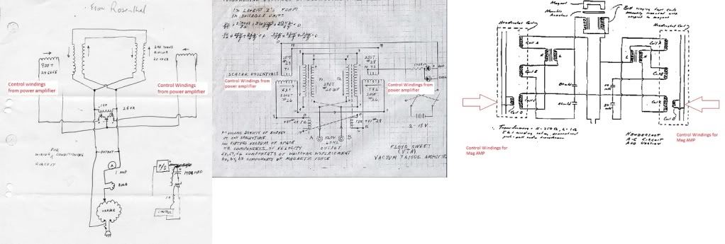
              I wanted everybody to see what John has mentioned about magnetic amplifiers in respects to his invention as well as comparison to the Hendershott, VTA, and countless others!!!

              What did John say that was very important about magnetic amplification? John mentions that “you want to self bias this from the pulse”. (post 131) This means that the half bedini/cole switch only controls the biasing!!! This brings a very interesting and important lesson to light!!! Remember what I learned from my experiment....it took very little input to control the inductance! Imagine the enormous amounts of magnetic amplification.

              Where?

              Between the differentials of the magnetic fields on the slaves!

              The slave coils in asymmetrical geometry are creating potential differences, no need for input!! I had it backwards!!! So again John is teaching us how to switch and control the magnetic field!!!

              Catch these streams!!!!

              I was originally thinking the slaves were control. I was wrong! I failed to see that the pulse determines the biasing!!! Please, I urge everyone to carefully read everything John has to say!! I missed this myself. I believe most of us are seeing this opposite because of me! I apologize if I have confused everyone with this. We only want to deal with control of magnetic streams. Otherwise we waste our input!!!

              Know this is where things get very interesting! John said that Floyd Sweet used a 100 W amplifier for control in magnetic amplification! He was even asked to leave after John found out what Floyd was doing. We don't have to waste a large amount of input to the control windings since we are dealing with the magnification of nature’s magnetic streams. Use the 18AWG. All we want to do is hook are paddles into the del-phi river!!

              So again, where is the energy? It’s at the drop below!!! How? Control the del-phi river with an electromegnet stream! Don’t see this? Look at the AWG size wire of both slave coils!!

              I certainly don’t want to get anyone off track here. We are all here to learn! Again John I can’t thank you enough, I hope I am going in the right direction, I’m here to learn.

              Here is your answer John to why the switch in my post was the downfall and wasting power.

              All the best,
              Jeremy Burnum


              Comment


              • Bedini GT3

                John,
                Would you please tell us the mounting degrees that you used for the axial coils.
                ------------------------------------------------------------------------------------------------------
                I said I have Ten coils that would make it 36 degrees each.------------------------------------------------------------------------------------------------------

                Or have we not made it that far? The axial magnets are at 36 degree spacing correct? one set of the five coils are out of phase with the other but both at 72 degrees each, correct?
                ---------------------------------------------------------------------
                Yes---------------------------------------------------------------------
                You told me before that its 2 short pulses (outside coils) and one long one to drive it around (central coil). In your video you stated that EVERYTHING was parallel. So the axial hub is in parallel with the bottom coils but each axial coil is in series with each other?
                ----------------------------------------------------------------------
                Yes a series arrangement switched 5 times.----------------------------------------------------------------------

                In my mind I see the the following, please correct me so I can get a clearer picture: the wheel is started into rotation. The axial is in neutral territory due to coil spacing.
                ---------------------------------------------------------------------
                Yes
                ---------------------------------------------------------------------

                The right coil fires first, the wave and spike are sent to the cap pulser which fires just right and dumps copious amounts of energy into batteries.
                ---------------------------------------------------------------------
                No
                ---------------------------------------------------------------------

                . A piece of that charge is sent to the axial motor now that the rotation has brought us into regauging territory. so the first series of n/s coils are energized (PMH) and we are pulled through the first coils lenz. Then the left coil fires, again to cap pulser to batteries. followed by the reguage and flipping of the poles on the axial to counter the lenz of the left coil. so the 2 short pulses are countered by the regauging motor no loss of rotational energy correct?. Then the center is fired a long duration due to the flux shaping and a large spike is sent to the cap pulser and sent to batteries to charge. the axial is in "neutral' territory again temporarily due to coil spacing and is carried through by flywheel rotation and the long stroke of the center coil.
                ----------------------------------------------------------------------
                No First pulse is sent to all coils and they repel then the re-gauge takes place. Very little power is returned to primary battery here. as the power, long flash is when the energy is re-gauged to suck all the magnets in. then it starts over again. then what is waste power goes to the cap. The Starr Motor has nothing to do with running of the machine it only acts as a generator if the macine is in run mode then it's circuits are off. It's just for Idling the machine.----------------------------------------------------------------------

                I would also like to add I appreciate the way you are teaching us. I am really starting to understand things I feel. Now I see why you are doing it this way. With the people participating in this thread we are actually learning. Other SG groups and ways of doing it make for a lot of chaos and bickering. No one wins that way and the people cant screw it up and say it doesnt work even though "they followed the directions". I am gathering materials to get underway. I am trying to get a flow chart to see if I really do "get it".
                Thanks again
                ----------------------------------------------------------------------
                I hope your all learning something here, but do not give up just yet more to come on ED
                John.
                ----------------------------------------------------------------------


                Originally posted by redrichie View Post
                Yep your reed will not make it terribly long.

                John,
                Would you please tell us the mounting degrees that you used for the axial coils. Or have we not made it that far? The axial magnets are at 36 degree spacing correct? one set of the five coils are out of phase with the other but both at 72 degrees each, correct?
                You told me before that its 2 short pulses (outside coils) and one long one to drive it around (central coil). In your video you stated that EVERYTHING was parallel. So the axial hub is in parallel with the bottom coils but each axial coil is in series with each other? In my mind I see the the following, please correct me so I can get a clearer picture: the wheel is started into rotation. The axial is in neutral territory due to coil spacing. The right coil fires first, the wave and spike are sent to the cap pulser which fires just right and dumps copious amounts of energy into batteries. A piece of that charge is sent to the axial motor now that the rotation has brought us into regauging territory. so the first series of n/s coils are energized (PMH) and we are pulled through the first coils lenz. Then the left coil fires, again to cap pulser to batteries. followed by the reguage and flipping of the poles on the axial to counter the lenz of the left coil. so the 2 short pulses are countered by the regauging motor no loss of rotational energy correct?. Then the center is fired a long duration due to the flux shaping and a large spike is sent to the cap pulser and sent to batteries to charge. the axial is in "neutral' territory again temporarily due to coil spacing and is carried through by flywheel rotation and the long stroke of the center coil.
                I would also like to add I appreciate the way you are teaching us. I am really starting to understand things I feel. Now I see why you are doing it this way. With the people participating in this thread we are actually learning. Other SG groups and ways of doing it make for a lot of chaos and bickering. No one wins that way and the people cant screw it up and say it doesnt work even though "they followed the directions". I am gathering materials to get underway. I am trying to get a flow chart to see if I really do "get it".
                Thanks again
                John Bedini
                www.johnbedini.net

                Comment


                • As these three YouTube videos relate to ED's work, and as it has been much discussed here, I thought they might be of interest.
                  YouTube - Transformer core tests part 1
                  YouTube - Transformer core tests part 2
                  YouTube - Homemade magnetic amplifiers made from common materials.
                  Last edited by Turion; 12-10-2010, 11:48 AM.
                  “Advances are made by answering questions. Discoveries are made by questioning answers.”
                  —Bernhard Haisch, Astrophysicist

                  Comment


                  • Bedini GT3

                    Turion,
                    Yea, that is right, you can't use this type of core because the magnetic streams do not run one agents the other to form the lock. The tape wound core is in layers and they will repel each other and leak. The only way to work with this energy is with plain old soft iron or cast iron and that is it. But there's more to all this which I can not get into right now. These type cores are designed to loose energy that is why you have them in everything. You may think not but you just saw it.
                    John B


                    Originally posted by Turion View Post
                    As these three YouTube videos relate to ED's work, and as it has been much discussed here, I thought they might be of interest.
                    YouTube - Transformer core tests part 1
                    YouTube - Transformer core tests part 2
                    YouTube - Homemade magnetic amplifiers made from common materials.
                    John Bedini
                    www.johnbedini.net

                    Comment


                    • After reading the Davis manual I noticed that almost all the U motors or generators had rod/axle switches. I wonder if Ed used them too so he could turn his PMH's on and off. Could it have looked like this?

                      rw
                      Attached Files
                      Last edited by everyidea; 12-10-2010, 10:09 PM.
                      My Calloway V Gate Motor Video

                      Comment


                      • Raymond Radus

                        Found a recent PBS video...

                        Anyone live near Lucas, KY and want to go tell Chris Radus what he has!!!

                        Skip to chapter 3 of 4...that's where the video starts. Enjoy and have a wonderful weekend!


                        Brent


                        Season 8: Episode 1 | History Detectives | PBS Video

                        Comment


                        • Originally posted by everyidea View Post
                          After reading the Davis manual I noticed that almost all the U motors or generators had rod/axle switches. I wonder if Ed used them too so he could turn his PMH's on and off. Could it have looked like this?

                          rw
                          I did some experiments today with a PMH and managed to charge a small iron bar while placed across the u-bolt. What's interesting is that the iron bar does not need to make contact with the u-bolt and can be charged while suspended closely. Once charged if you flip the iron bar (reverse the ends) and charge it again it will go neutral. "Ring twice" may be referring to charge on (create dipole) and charge off (neutral).

                          Also I found that using cold roll steel retains more magnetism when charged and neutralizes flat when reversed charged.

                          Ecoman
                          Last edited by Ecoman11; 12-10-2010, 10:56 PM.

                          Comment


                          • pmh motor test 1

                            Hi all

                            As Jetijs asked me to do a Video of the test pmh pulse motor
                            here it is

                            Just for info i elevated the PMH prods something higher so to face the ring magnet on the top of diameter , and it work better than when i center the prods in the center of the ring magnet. Perhaps it is a mean to get "sharper effect as per a superpole" ?

                            No pretention at all, and always on the hard learning way

                            Hope this helps

                            good luck at all

                            Laurent

                            YouTube - pmh motor 1

                            Comment


                            • Thank you Laurent!
                              It's better to wear off by working than to rust by doing nothing.

                              Comment


                              • good video woopy,

                                i always enjoy your videos....more please more

                                Comment

                                Working...
                                X