Announcement

Collapse
No announcement yet.

Bedini Ferris Wheel Regauging Motor

Collapse
X
 
  • Filter
  • Time
  • Show
Clear All
new posts

  • Bedini GT3

    John K,
    How can I help you. did you get it running? I would study my coils as I said the coils are two different impedances and that the coil must be big in the center double the outside coils I could measure them if you want.
    John
    John Bedini
    www.johnbedini.net

    Comment


    • Hi John B,

      Yes, I got it going. Just the main coil for now as I want to master the mag amp side of it before I add the slaves.

      Here's a quick video of where I'm up to.

      YouTube - Bedini S1GT

      I have an idea I want to try with the Mag Amp in that the two thinner windings are used to a) bias the coil at the ideal operating point and to b) use the winding to control the inductance (or permeability) of the coil for maximum and efficient power transfer through the power windings when the Bedini/Cole circuit fires.

      I'll keep playing around and let the group know how I'm going. I may go digital with the switching on you though - 1 hall input can give me the flexibility to adjust the Mag Amp coil bias, as well as the power winding timing and dwell.

      I was just wondering of the 2 thicker windings of the centre coil are connecetd in series or parallel and if in series, are they in phase? My gut tells me they are.

      I will keep studying and testing.


      John K.

      Originally posted by John_Bedini View Post
      John K,
      How can I help you. did you get it running? I would study my coils as I said the coils are two different impedances and that the coil must be big in the center double the outside coils I could measure them if you want.
      John
      http://teslagenx.com

      Comment


      • Bedini GT3

        @all,
        Yes the inductance does change when the magnets pass the pole. The one thing that you can not do in the machine is twist the wires. Now each wire in the main coil has it's own resistance so this is offset a little when it turns on sort of like a mag amp but pulsed DC or more like PWM because of the switching so I had to sit and tune it for maximum power low RPM.

        This is a very tedious to do as if I did not get just right I could not self start the machine. No one posted a Video of me showing it at the convention yet but someone out there has it. When I would start it from a dead stop it would accelerate backwards and slam agents three magnetic fields and dead stop then leap forward right up to 16RPM's that is how I knew I had the timing right. You all have done excellent work on this group. But now I'm going to do something I always wanted to do with a new machine just like this we must make it run with no input. Great group glad I could be here.
        John B
        John Bedini
        www.johnbedini.net

        Comment


        • Base coils

          John B,

          You have said very little about the (slave) outer coils except for the impedance being half that of the center coil. Are the slave coils made up of the same number of windings as the center coil? Is the length of the (4) windings in the center coil all the same length (4000 turns)?

          Also, question in regards to the size of the cores. Would you suggest that the cores be bigger than the width of the magnets? We have 6"x2" magnets...should we make them at least 2" diameter or bigger?

          Thanks for your continued guidance!!!


          Brent


          Originally posted by John_Bedini View Post
          John K,
          How can I help you. did you get it running? I would study my coils as I said the coils are two different impedances and that the coil must be big in the center double the outside coils I could measure them if you want.
          John

          Comment


          • Bedini GT3

            John K,
            Just use a little DC bias on one winding but reverse, you must choose the resistor, may also require a capacitor in series. I have been watching Chuck H at work with his machine I have not seen him charge the batteries yet but he can also tell you that it's not easy to tune. Just ask him he is on this group. Do not give up I did not learn this overnight.
            John
            John Bedini
            www.johnbedini.net

            Comment


            • Bedini GT3

              Brent,
              No the slave coils are 1/2 the impedance with single windings this all makes up a parallel transformer with different impedances This is very hard to explain but it's almost like having a time delay between coils as you can see this in the recharge output power. Three very YouNeak pulses of over 500 amps peak in one second.
              John Bedini
              www.johnbedini.net

              Comment


              • Base coils

                John B,

                Thanks!

                Were there any diodes used with the windings for paralleling the the coils?


                Brent


                Originally posted by John_Bedini View Post
                Brent,
                No the slave coils are 1/2 the impedance with single windings this all makes up a parallel transformer with different impedances This is very hard to explain but it's almost like having a time delay between coils as you can see this in the recharge output power. Three very YouNeak pulses of over 500 amps peak in one second.

                Comment


                • Thanks John,

                  I think I get what you mean. If the coil is biased reverse then the coil will take longer to charge as it will fight the bias, but then when the coil discharges, it discharges faster and with a bigger "whallop" which means a bigger spike to the cap.

                  I will use a large rheostat or potentiometer to find the right resistance for the bias winding. The 2nd thinner #18 winding I will experiment with using in series with the bias winding and use the passing rotor magnet to generate current to influence the DC bias.

                  I agree with Chuck H that it is hard to tune, which is why I want to go with a PIC as a PWM and use the hall as the PIC input to be able to adjust the switching and timing digitally. I'm also thinking of Sziklai pairs switched by optos off the PIC in place of the MJL21194 & MJL21193 to do the power winding switching. Minimal loss and faster switching.

                  Gotta test these ideas on the bench though.


                  John K.


                  Originally posted by John_Bedini View Post
                  John K,
                  Just use a little DC bias on one winding but reverse, you must choose the resistor, may also require a capacitor in series. I have been watching Chuck H at work with his machine I have not seen him charge the batteries yet but he can also tell you that it's not easy to tune. Just ask him he is on this group. Do not give up I did not learn this overnight.
                  John
                  http://teslagenx.com

                  Comment


                  • Bedini GT3

                    Brent,
                    No diodes used.


                    Originally posted by BrentA929 View Post
                    John B,

                    Thanks!

                    Were there any diodes used with the windings for paralleling the the coils?


                    Brent
                    John Bedini
                    www.johnbedini.net

                    Comment


                    • Originally posted by John_Bedini View Post
                      Brent,
                      No the slave coils are 1/2 the impedance with single windings this all makes up a parallel transformer with different impedances This is very hard to explain but it's almost like having a time delay between coils as you can see this in the recharge output power. Three very YouNeak pulses of over 500 amps peak in one second.
                      John,

                      Were the slave coil wires unifilar wound with 18 AWG?

                      Thanks,

                      Dave

                      Comment


                      • Originally posted by genessc View Post
                        Howdy John K,

                        I built me a magnetic amplifier to learn and study from. Its here in this youtube vid I put up last friday.

                        YouTube - 1000 Watt Magnetic Amplifier running 500 watts of lamps.

                        A basic Mag amp needs one AC winding and one Control winding which is controlled with DC power. (or so the mag-amp book says.) However theres a homemade mag-amp site on the sparkbangbuzz site that is what I made use of to build my mag-amp using 3 of the same model 1000va transformers.

                        In effect only one of the transformers is the load transformer. The other two transformers are used to create an asymetry on ONE side of the output load transformer. The other side of the output from the load transformer goes directly to the load. The two transformers are wired up on the other end of the load winding in series and finally out to the load. The DC bias of those two trafos (short for transformers) is then wired in "BFCEC" which means bifilar common end connected, which nulls the inductance of the two windings put in such relation or would if they shared a common axis and core, however in this instance it just seems to make it so the bias winding can't be shorted to cause the AC load to be powered. If you short the bias winding and the load gets power, then the DC bias windings are connected wrongly.

                        The interesting thing about a magnetic amp is that it "switches current". The voltage sine wave is always present on the load trafos output winding so that if you put a resistive lamp load over the winding, the sine will go flat as there is no CURRENT there to keep the sine from sagging. What happens if you use a cap as the load? I don't yet know, but will soon.

                        The idea is that the cap won't act as a short to the load so the full sine should still be let thru but the rate of charge would be based on the amount of current needed to bring up the rated farad capacity of the cap to the volts being output from the load trafo.

                        This then brought me to think about chopping the DC pulse bias. So I did that. I found that I need an ON duty of about 98% to get full output from the trafos load winding. (this without the cap on the DC bias to hold the charge, which I think might change the DUTY a little ... hopefully.) I need to add a cap there and see if it doesn't allow me to reduce the ON duty further while still being able to retain the output from the mag-amps load winding at full voltage. (albeit chopped).

                        So Chopping the DC bias on this mag-amp made little improvement over the power needed to turn it on or off. I am almost just as well able to use the DC bias in constant on as theres not much savings in pulsing/chopping the DC bias pulses if I still want the full rated volts output in the sine.

                        Thats my study of the magnetic amp I built on my bench so far. Thoughts/comments? how does this apply to the ferris wheel setup?

                        Seeing as the SG is a rotary magnetic amplifier that switches on a single polarity, perhaps the field shaping of the rotor is getting the waveform to trigger the drive circuit just right so that its better able to work with the now biased sine waveform that appears to be emitting a single polarity ramped over time versus the sudden drop to zero perceived as the field reguaging function on the typical SG perhaps? The balanced sine wave has the same time to drop to zero as it took to get from zero to the peak. The biased waveform presented in Nvissers vid shows that the neo has altered this sine into more of a sawtooth wave.

                        Good stuff... Hope I'm not off-topic sharing the mag-amp I mocked up.

                        Take care all,
                        Gene

                        Hi Gene,

                        Thanks for the Spark,Bang,Buzz link, for those who are interested in some basic mag amp stuff its well worth a look

                        Homemade Magnetic Amplifiers.

                        Regards
                        "Once you've come to the conclusion that what what you know already is all you need to know, then you have a degree in disinterest." - John Dobson

                        Comment


                        • You bet Ren.

                          I put a 330uF cap on the DC bias side to see if that would let me get the DC ON time below the 98% but it only reduced the heating of the transistor slightly. I'm not sure if using a larger capacity would make much difference.

                          Next is to put a cap on the output and see how that works as the load.

                          Take care,
                          Gene

                          Originally posted by ren View Post
                          Hi Gene,

                          Thanks for the Spark,Bang,Buzz link, for those who are interested in some basic mag amp stuff its well worth a look

                          Homemade Magnetic Amplifiers.

                          Regards

                          Comment


                          • Mag Amp

                            Hi Jeremy,

                            I've been studying and testing the Mag Amp, trying to figure it out.

                            A couple of questions:

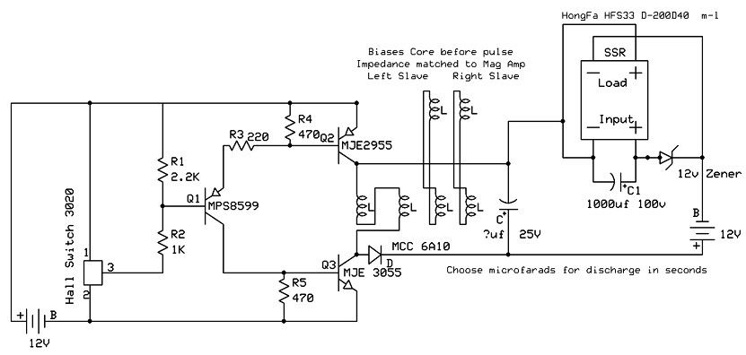
                            1. Until now I thought the slave coils were in parallel with the 2 power windings on the main coil. Your schematic shows the slave coils in parallel with the 2 thinner windings on the main coil. Are the slave coils purely used to bias the main coil? (As a Mag Amp)

                            2. In the Mag Amp material I have studied it is advisable to set the DC bias of one of the windings to the "ideal operating point", where a small change in power in the control winding reflects a large change in inductance in the power windings. Is an LC meter the only practical way to measure the inductance of the power winding whilst adjusting the amount of DC bias?

                            Any other related information will also be helpful.


                            John K.

                            Originally posted by jerdee View Post

                            I want to discuss the principle of rotational magnetic amplifiers. I had to experiment with this principle, so I tried this....

                            • Take four wires, any size, but keep them same length and size for now. Keep this simple.
                            • Wind three wires as a trifilar coil and the fourth one by itself. The trifilar will be the Mag Amp. While the separate coil will be CONTROL. MAKE SURE TO NOT LITZ THE WIRES OR THIS EXPERIMENT WILL NOT WORK!!!
                            • On the Mag Amp coil, connect one power strand end to the top of the next power strand. This will be two power strands in series!! This will create high inductance on the windings!!! Measure the inductance of these windings and keep the LC meter connected.
                            • Now short the third available winding on the trifilar and measure the series inductance. It drops!!
                            • Now take the third winding ( control strand ), place it across a 9 volt battery and measure inductance.
                            • Flip the polarity on the 9 volt. What do you get? A gigantic inductance rise or lowering of the series power wires depending on 9 volt polarity. You can swing the inductance either way dramatically with very little input.
                            • Now connect the 4th single strand coil left to the third control winding instead of the 9 volt battery. This extra coil should be in PARALLEL to the control winding of the trifilar mag amp. Think of this as the impedance matched slave coils on the sides.
                            • Take a large Neo and slam it on top of the slave control winding! Guess what, you control the inductance to the Mag amp coil very easily!!! Both up and down!!! This all requires an A/C wave to control the inductance!!


                            Why is mag amp technology a lost art?! It's beyond me. BTW, the early marconi stations were based on Tesla's work with intense grounding (bolinas county, CA) uses Alexanderson's mag amp work!! I find this very interesting. Read Alexanderson's patents. Some of the earliest work of mag amps.

                            So here is a proposed wiring of the Mag Amp with Slaves windings in parallel. I have moved the diode close to the switch.
                            There is still lots of room for improvement here. For example, I do not show the capturing of the reactive impulse from the slaves as well as the axle generator. But this is a good start for all of us to begin and understand the process here. Thanks goes to Vissie and Matt for the SSR potential inverted switch. This sche is set for 12volts but can easily be set to higher voltage inputs and outputs.


                            Now imagine the Mag amp coil is pulsed in low inductance and released in high inductance!!! A rotating wheel self biases the mag amp, and still only requires one switch from the input!!

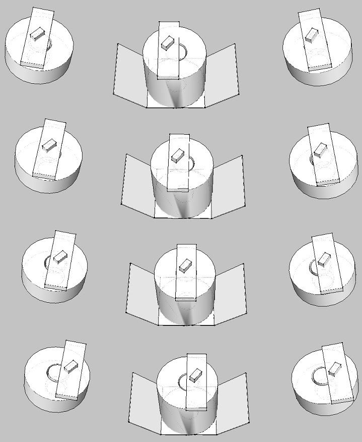
                            Here is a simple timing of the slaves vs. master mag amp coil in CCW rotation, just to show this principle of variable inductance control from rotation.


                            Now everyone needs to see the scalar south (fake south) that is pointing out in between the neo-tipped weak north’s. This is where the triggering of the hall switch needs to be. Since the neo is creating an asymmetrical large south compared to the north, the scalar south is going be very pronounced. Also the rotation of the neo causes the south field to cover a much larger area between the 22.5 degree sections. I or someone soon will talk about this later. This gets into geometry of the axle in generation mode to prevent lenz law!! Look at the sweet 16 diagram from John Depew that John posted, you should see the coils in the center now!! Also notice that the pie shaped barium ferrite magnets are pointing directly at these monopoles!! Ring the bell twice!! Look at the line at the 16 pole sun. We all need to see how to prevent lenz's law with the 10 coil axle.

                            I trust that this is mostly on the correct path John. This is by far the most important device to understand how to manipulate and make a man made flux field from Ed’s work as it is correct.

                            Hope this helps.
                            Jeremy Burnum
                            http://teslagenx.com

                            Comment


                            • Hey John K

                              Where was that post from Jerdee at I've never seen it before.

                              Comment


                              • Almost there!

                                John B,

                                Found several items today that will help Scott and I complete the bottom coils of our build. Found some great reels that are 10.5" wide with 3" holes for cores and found a magnet wire distributor here in Dallas, TX that has the larger (75-80 lb.) spools of wire. Cheaper per pound than the normal 11 lb. spools that everybody carries.

                                All we lack is to get over that last little hurdle of confidence to pull the trigger on a potential $1500 purchase. We both have different interpretations of all the information that has been presented by you and others here. I think that there are only 2 wires (2 - #15) on the center coil and he thinks that there are 4 wires (2 - #15 and 2 - #18). Then of course there is the whole thing about half the impedance.

                                Any interest in proving one of us wrong?

                                Thanks again for your help last night!


                                Brent

                                PS Eager to see our 6' wheel begin to spin!!! "Junior" as we like to call it!

                                Comment

                                Working...
                                X