Announcement

Collapse
No announcement yet.

Theoretic foundation of Meyer's Cell: the electret effect

Collapse
X
 
  • Filter
  • Time
  • Show
Clear All
new posts

  • Theoretic foundation of Meyer's Cell: the electret effect

    Posted my theory about how Meyer's fuell cell worked, based on some earlier posts at this forum, over here:

    Theoretic foundation: the electret effect

    It contains various references to a/o Prof. Claus Turtur and John Bedini's "cold boiling" batteries and is essentially an exercise in "connecting the dots" between Turtur, Meyer, Bedini and (old-school) Electrolytic Capacitors....

    To me, all the pieces of the puzzle appear to drop into place.


    -- Arend --

  • #2
    Originally posted by lamare View Post
    Posted my theory about how Meyer's fuell cell worked, based on some earlier posts at this forum, over here:

    Theoretic foundation: the electret effect

    It contains various references to a/o Prof. Claus Turtur and John Bedini's "cold boiling" batteries and is essentially an exercise in "connecting the dots" between Turtur, Meyer, Bedini and (old-school) Electrolytic Capacitors....

    To me, all the pieces of the puzzle appear to drop into place.


    -- Arend --
    Meyer have apply old technologies dated 1900 and nothing else.
    Meyer need a plasma .. plasma is the way and you need energy for create plasma.. all energy and life is started from sun .. ether is formed from positive sun particles.. how an battery work? how an battery is formed? you don't need of advanced technologies or complicate devices.. Humans must think simply for reach the illumination..

    Comment


    • #3
      Originally posted by tutanka View Post
      Meyer have apply old technologies dated 1900 and nothing else.
      Exactly! I referred to this 1938 book on electrolytic capacitors, which explains exactly how these were made:
      FaradNet Electrolytic Capacitor Book Contents


      Meyer need a plasma .. plasma is the way and you need energy for create plasma..
      Correct again!

      The plasma is created within the fluid by the electric field created by the strongly polarized dielectric layers on the tubes, which field should exceed the dielectric breakdown strength of water, which creates "streamers" a.k.a. "sparks" or "plasma". And the energy needed to create the plasma is extracted by the polarized dielectric from the aether, as explained by Prof. Turtur's thesis. It's all really a matter of connecting the dots.
      Last edited by lamare; 05-21-2013, 08:46 PM.

      Comment


      • #4
        Originally posted by lamare View Post
        Exactly! I referred to this 1938 book on electrolytic capacitors, which explains exactly how these were made:
        FaradNet Electrolytic Capacitor Book Contents


        Correct again!

        The plasma is created within the fluid by the electric field created by the strongly polarized dielectric layers on the tubes, which field should exceed the dielectric breakdown strength of water, which creates "streamers" a.k.a. "sparks" or "plasma". And the energy needed to create the plasma is extracted by the polarized dielectric from the aether, as explained by Prof. Turtur's thesis. It's all really a matter of connecting the dots.
        Meyer use thermal plasma..

        Comment


        • #5
          Originally posted by tutanka View Post
          Meyer use thermal plasma..
          Yes, look for "glow" in the thread I posted and the documents linked.

          The glow is created by tiny sparks, plasma, within the fluid.

          I collected some documents about dielectric breakdown, the process which takes place within the fluid, which may be of use:
          Directory contents of /pdf/Reference_Material/Dielectric_breakdown_Avalanche_Multipactor/
          Last edited by lamare; 05-22-2013, 10:04 AM.

          Comment


          • #6
            Originally posted by lamare View Post
            Exactly! I referred to this 1938 book on electrolytic capacitors, which explains exactly how these were made:
            FaradNet Electrolytic Capacitor Book Contents


            Correct again!

            The plasma is created within the fluid by the electric field created by the strongly polarized dielectric layers on the tubes, which field should exceed the dielectric breakdown strength of water, which creates "streamers" a.k.a. "sparks" or "plasma". And the energy needed to create the plasma is extracted by the polarized dielectric from the aether, as explained by Prof. Turtur's thesis. It's all really a matter of connecting the dots.
            Water as a Dielectric - YouTube

            Comment


            • #7
              Stan Meyers Devices

              The voltage Intensifier Circuit

              Tesla Patent 381,970 - System of Electrical Distribution

              The Water Fuel Cell

              Tesla Patent 567,818 - Electrical Condenser

              The Air Processor

              Tesla Patent 568,177 - Apparatus for Producing Ozone

              The Engine

              Tesla Patent 517,900 - Steam Engine

              The Igniter

              Tesla Patent 609,250 - Electrical Igniter for Gas Engines

              The Circuit Controller

              Tesla Patent 336,961 - Regulator for Dynamo-Electric Machines

              Read and analyze!

              Comment


              • #8
                Plasma Is The Key

                Meyer use PLASMA ..

                Puharich use PLASMA..

                THE KEY IS PLASMA FOR CONVERT THE LOW ENERGY INTO HIGH ENERGY
                Last edited by tutanka; 06-23-2013, 01:16 PM.

                Comment


                • #9
                  combination approach

                  (not for on demand but general production) Since one of the uses of an ultrasonic horn is to induce instantaneous chemical reactions. Is it possible that using an ultrasonic horn in combination with the electricity could have a positive effect? Or just rebind the H2 to the O
                  Last edited by Hrothgar; 06-01-2013, 09:06 PM. Reason: Clarafication

                  Comment


                  • #10
                    Originally posted by Hrothgar View Post
                    (not for on demand but general production) Since one of the uses of an ultrasonic horn is to induce instantaneous chemical reactions. Is it possible that using an ultrasonic horn in combination with the electricity could have a positive effect? Or just rebind the H2 to the O
                    Yes, that is definitely possible. The gas bubbles tend to stick to the tubes and thus make it harder for water atoms and/or H+ and OH- ions to reach the region where the strong electric field is present.

                    So, acoustic resonance, either in the length direction of the (organ like) pipes or perpendicular with respect to the tube surfaces, would likely help to prevent the gas bubbles from sticking to the tube surface and thus improve the amount of gas which can be produced per unit of time.


                    Update: some earlier considerations on acoustic resonance here:
                    http://www.energeticforum.com/water-...tml#post111120
                    [4/2/2007 11:29:10 PM] Tao says: UNTIL, I just watched that video
                    again..........
                    [4/2/2007 11:29:50 PM] Tao says: Look at what Dave was pulsing his DC at in
                    the video: 5714Hz!!!! At 1:11 in the video you can see what he was pulsing
                    at.......
                    [4/2/2007 11:30:58 PM] Tao says: Based on the equation for acoustic
                    resonance, Dave was pulsing his tubes at the EXACT frequency at which those
                    tubes will resonate ACOUSTICALLY in FRESH WATER... So, my finding was
                    basically his: Dave found the BEST gas production at the VERY SAME frequency
                    that just so happens to be where his tubes resonate ACOUSTICALLY IN WATER
                    ... HMMM...
                    Maybe it is nothing at all but a coincidence, but maybe there is just
                    something to it........................

                    Something else about the tuning because I can't wrap my head around yet I believe the 2mm gap of the small tubes is also a harmonic of the open tube frequency. Then add the the large tube-set at 4 octives below the small tubes and its gap of 1mm another harmonic of the picture.

                    There has to be some intense science behind this to achieve the final outcome that just hasn't been evaluated yet.
                    http://www.energeticforum.com/water-...tml#post111121

                    Of course, acoustic resonance also keeps the fluid in motion, thus forcing atoms and ions into the reaction area, and thus also increasing the production rate.
                    Last edited by lamare; 06-02-2013, 03:55 PM.

                    Comment


                    • #11
                      Originally posted by tutanka View Post
                      Meyer use PLASMA ..

                      Puharich use PLASMA..

                      THE KEY IS PLASMA FOR CONVERT THE LOW ENERGY INTO HIGH ENERGY
                      Is there any evidence, documentation or witness reports that any of Meyer's more fancy stuff has ever been shown to work?

                      For all I know, what *has* been shown to work is only the fuell cell, as replicated up to a certain degree by Ravi and Lawton. For all we know, all the other stuff may have worked, but it may just as well have been total failures. To my knowledge, we just don't know what worked and what not, other than the basic fuell cell. All the rest may have been "under construction" and may never have actually worked, but then again, it may also have worked. But since we don't know what worked and what not, we are merely performing guesswork and may be chasing a ghost.

                      As for Puharich, his son declared on a radio show in Dutch that his father probably parented his stuff in order to raise funds and that he doubted that it ever actually worked:
                      Thema Uitzending: Vrije Energie – 24 september 2011 » Argusoog

                      It must be noted, however, that his son only visited his father during summer holidays.
                      Last edited by lamare; 06-04-2013, 07:35 PM.

                      Comment


                      • #12
                        An interesting detail can be found in Patrick Kelly's book:

                        Practical Guide to Free-Energy Devices - Chapter 10

                        It is said that Stan ran his VolksWagen car for four years, using just the gas from four of these units which had pipe pairs 16-inchs long. A very important part of the cell build is the conditioning of the electrode tubes, using tap water.
                        This suggests that it is entirely possible that the only version of Stan's system that actually worked is the system with just the tubes. I remember having seen a video of some Dutch guys visiting Stan to see his car at a moment the car was not working. It may very well be that his injectors never actually worked.

                        Comment


                        • #13
                          Both Sterling D. Allan and TechZombie posted an article about the info presented here:

                          Article:Theoretical Foundation for the Functioning of Meyer's Fuell Cell - PESWiki
                          Dutch Engineer may have the Missing Link To Hydrogen Cell Efficiency

                          First of all, I wish to express my gratitude to them for publishing this, because the more this information is being spread around the better. Zomb also made a collection of documents with info about this project: https://keychests.com/?c=150

                          A further collection of documents can be found at my server:
                          Directory contents of /pdf/Patents/Meyer/

                          And finally, there is (of course) our Bible, Patrick Kelly's guide, which is also hosted at my site now, because Patrick is retiring and was kind enough to send me the contents of his site. Particularly interesting with regards to this project are chapters 5 and 10, but at the front page there are also more documents under "Electrolyser construction plans and Suppliers":
                          Practical Guide to Free-Energy Devices - Chapter 5
                          Practical Guide to Free-Energy Devices - Chapter 10
                          http://free-energy-info.tuks.nl/

                          All right, now Zomb asked me the following by email:
                          This can be a great open source project since it is so easy to begin.

                          We need to give them more guidance. on how to start.

                          for example you say high voltages are required if we use dc right? 7x higher than 20kv? that is extremely high. very lows amps. .1ma will keep the water cool and keep it from evaporating I assume. but we need to guide them on what transformers they should use to experiment with such voltages.

                          Also the nature of the cell itself.
                          Since I am not such a good builder myself, I am working together with a friend, and we are planning to make a fuell cell for experimenting. This afternoon, I made a shopping list with some considerations for getting started.

                          We considered both the option of using rectangular plates, as well as round pipes as Meyer used. We decided to go for the latter and stay as close as possible to Lawton's design, because the components for that are readily available in the UK.

                          Essentially, what we plan to do is to do what Dave did, but only exchange the Stainless Steel pipes for Aluminum ones, because then we can control the growth of the dielectric layer which does all the magic. What will also be different, of course, is the process for growing the dielectric layers. For that, we need to study the book:
                          FaradNet Electrolytic Capacitor Book Contents

                          For those who are not convinced yet that there is more to a dielectric than meets the eye, I wholeheartedly recommend watching this video:
                          https://www.youtube.com/watch?v=9ckpQW9sdUg

                          To quote Eric Dollard on this one:
                          Tuks Unsorted KieknWatTWordt Stuff : Energetic Form Posts
                          There are some very serious misconceptions in the world of Electrical Engineering today. (The writings of Oliver Heaviside and Proteus Steinmetz gravely warned about this...) Let us start with the YouTube MIT Physics Demo video that Armagdn03 posted a link to on 11-10-2009 on page 2 of this thread.

                          This is a good demonstration for several reasons.

                          1.) Glass is a dielectric which can store electrical energy within its physical form. This should be common knowledge and not a surprise to anyone today…

                          2.) That this simple fact and reality “blows some people’s minds” clearly illustrates that it’s just all gone way, way, too far… The Einsteinian Lie has succeeded in instilling a mind virus in most everyone and also in confusing Main Stream “Scientists”, who today waste billions of dollars of funding each year, only to chase their own tails in a canonic sequence.
                          All right, the shopping list:

                          First, the tubes. Stan used 16" or 40 cm. Lawton used 1" outside diameter for the larger tubes and a gap between the tubes of about 1-2 mm. In the Netherlands, tubes can be bought here:
                          RONDE BUIZEN - IJZERSHOP

                          It should be noted that there normally already is a dielectric layer on the tubes, which will most likely have to be removed. We still have to figure out how to do that, because the tubes will have to be roughened in order to increase their surface area, but we will probably go for cleaning and etching, since that is the most easy with round pipes.

                          We plan to go for 25x20 for the outer tubes and 16x12 for the inner tubes, so we get a gap of 2 mm.

                          We still have to decide about the number of pipes, which will either be 6 or 9. Lawton used 6, but Dr Scott Cramton used 9, which gives the option of running with three phases.

                          However, as it looks now, I prefer to stay as close to Lawton as possible, because that gives the best comparison with available results and the available kits we plan to use are also designed for that configuration.

                          So, we would need 6 x 40 cm of both tube sizes.

                          For the housing of the cell and other components, we are looking at this site, which sells almost all the needed parts and electronics under one roof:

                          Dave Lawton - Electrolysers

                          For the use of 40cm tubes, we need 1 plastic tube of 50 cm length:
                          Dave Lawton Electrolyser 110 x 500 x 3mm Acrylic Tube - Dave Lawton - Electrolysers

                          And 2 end caps:
                          Dave Lawton Electrolyser 110mm End Cap - Dave Lawton - Electrolysers

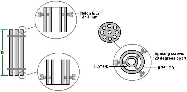
                          Further, I would consider using plastic bolts instead of rubber slides, so I would also opt for a set of these:
                          Scott Cramton Plastic Screws Kit - Dave Lawton - Electrolysers

                          See this drawing:


                          For the electronics, there are two options available, as far as I understand:


                          1) The manual controlled PWM version:
                          Dave Lawton PWM Kit - Dave Lawton - Electrolysers

                          2) The PLL auto-tuning kit, which can also be manually controlled, *but* also has an auto-resonance tuning circuit:
                          Dave Lawton PLL Full Kit - Dave Lawton - Electrolysers

                          Of course, the PLL kit has its advantages, but it is more expensive.
                          For these, one can choose for full kits, just the soldered PCB or a bare PCB.


                          Besides that, one needs a coil. Perhaps buy a couple, because they are not expensive and the wiring and such may be handy for further experimenting:

                          Dave Lawton Pattern Bifilar Inductor Kit - Dave Lawton - Electrolysers

                          And, a "fixing kit" is also worth considering:

                          Dave Lawton Electrolyser Stainless Steel Fixings Kit - Dave Lawton - Electrolysers

                          The only thing that is missing in the shop are the place holders. There are these:

                          Scott Cramton Electrolyser 150mm diameter tube mounting plates - Dave Lawton - Electrolysers

                          But these have 9 holes of 19 mm diameter, which could be drilled up, but then you still have 9 holes instead of 6. So, we haven't decided on this part yet.

                          What is left from the shopping list is at least these items:

                          1) electrolyte solution. A choice will have to be made from:
                          FaradNet "Electrolytic Capacitors" Chapter 5

                          2) Cleaning / etching aluminum. This will have to be studied and a choice made from:
                          FaradNet "Electrolytic Capacitors" Chapter 4

                          Grinding is also possible, but that might be hard to do with round pipes. Bob Boyce did this, but he used flat squared plates....

                          3) bubbler and other safety material for mounting on a test-engine and eventually perhaps in a car.

                          4) Gas production meter.

                          5) Insulation material around the outer tubes and the inner side of the inner tube. This is optional, but it is advised by Kelly to be used.


                          Finally, according to the information in Kelly's chapter 10, tuning of the pipes is important:
                          Practical Guide to Free-Energy Devices - Chapter 10

                          It needs to be stressed that Dr. Cramton’s cell is very close in construction principles to Dave Lawton’s cell and the quality of construction is very important indeed. The first and foremost point which can be easily missed is the absolutely essential tuning of all of the pipes to a single, common frequency. This is the equivalent of tuning a musical instrument and without that tuning, the essential resonant operation of the cell will not be achieved and the cell performance will not be anything like the results which Dr. Cramton and his team are getting.
                          Now that does not mean one cannot achieve results in terms of energy extraction from the aether without resonance, given what Bedini reported about his batteries. However, apparently it is required for obtaining an optimal gas production, so I think it would be a good idea to follow this advice.

                          Comment


                          • #14
                            I tried using aluminum tubes with a grown dielectric. I still couldn't prevent the formation of 'aluminum foam' in the water. Hope you have better luck!. One thing I have always though about concentric tubes is because of the larger surface area of the other tube you automatically have a difference in 'voltage potential'. Like you can make an earth battery with electrodes made of the same metal if the surface area is different. So it gives you a head start in the difference of potential from inner tube to outer tube.

                            Comment


                            • #15
                              Originally posted by Jeff Pearson View Post
                              I tried using aluminum tubes with a grown dielectric. I still couldn't prevent the formation of 'aluminum foam' in the water. Hope you have better luck!. One thing I have always though about concentric tubes is because of the larger surface area of the other tube you automatically have a difference in 'voltage potential'. Like you can make an earth battery with electrodes made of the same metal if the surface area is different. So it gives you a head start in the difference of potential from inner tube to outer tube.
                              What electrolyte did you use to grow the layers?
                              Did you leave the electrolyte in?


                              The action should happen at the positive plate, so best take the outer tube as positive. The other plate should be just a contact plate, no capacitor function there. At least in a normal elco, that is.


                              Update: just found out we had a thread about this theory before: http://www.energeticforum.com/john-b...et-effect.html
                              Last edited by lamare; 06-06-2013, 09:19 PM.

                              Comment

                              Working...
                              X