Announcement

Collapse
No announcement yet.

Stan Meyer's VIC UNICORE setup

Collapse
X
 
  • Filter
  • Time
  • Show
Clear All
new posts

  • Stan Meyer's VIC UNICORE setup

    Hi all,

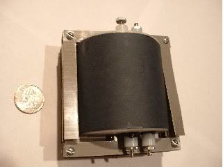
    Here are some pics that show 'one possibility' of how to make a VIC. I am not saying this is the best or anything. It IS a unicore like Stan Meyer talks about in 'some' of his writings. The primary/secondary power is on the same core as the bifilar chokes.

    IGNORE THE QUADFILAR WINDINGS ON THE COILS...Meyer's only used 2 windings on each. Just look at the concept of the metal and how it is constructed as a simple example of 'how' you could make a unicore for easy winding.

    The core is not physically attached to the spool...at least not solidly. You can remove the core....this makes for easy winding on the spools, then you can slip in the core. the core obviously has a cutout to mount the other part of the core to it very flatly.

    Some may think that a core like this is the same as a torroid (circular) core, but please don't think in these terms. If it is not a round core, then literally, it is NOT a torroid.

    Anyway, on the unicore design, just remember that the magnetic field created by power coil side is partly available at the choke core side.


    I believe that bundled welding rod for a core works better so it lets go of the field quicker and has less eddy currents BUT, this is just a plain simple way to make a unicore.
    Sincerely,
    Aaron Murakami

    Books & Videos https://emediapress.com
    Conference http://energyscienceconference.com
    RPX & MWO http://vril.io

  • #2
    stanly used a pulse train with the VIC because the vic produces static. the pulse train would have a static pull on the negative electrons in the water molecule, the vic would damage and dislodge a few electrons when the pulse train was at work. when the pulse train is not at work i cant remember if the damaged electron is given back then dislodged? or totaly taken away for good, missing electrons.

    anyways the vic was a very small setup, from the information i have looked into the chokes would fit into a sparkplug and worked at just over 20 thousand volts.

    just my 2 cents, and i am usually wrong lol, just my ideals.

    Comment


    • #3
      What material is bundled welding rod made of?

      Comment


      • #4
        core material

        Iron/steel for welding rod. It is fairly cheap last time I bought some to make cores out of. I'm sure there are a lot of different types but that is all I have used.
        Sincerely,
        Aaron Murakami

        Books & Videos https://emediapress.com
        Conference http://energyscienceconference.com
        RPX & MWO http://vril.io

        Comment


        • #5
          Have they been tested whit a WFC (capacitor)?
          - Behold the truth -

          Comment


          • #6
            Good Work Aaron!

            I have built Stan Meyers VIC. Once It is completed and tested I will post about it so others can understand how it works, why it works, and why it is built the way it is. It will be a while before I get it completed and tested though. Probably a month or two.


            Last edited by HMS-776; 11-09-2009, 11:19 PM.

            Comment


            • #7
              I too have made the figure 6-1 VIC transformer:


              Now notice the correct way to wrap the primary coil as per Meyer's instructions on figure 6-1.
              Also notice that the secondary and the chokes really are one coil, that is why each of the bobbin spaces inductances must match, for it really is an electronic means to make an alternator and in an alternator all of the stator coil loops of each phase group match up perfectly.
              In the way that I make the VIC transformers is with three seperate bobbins for ease of winding them up because I wind them by hand.
              As transformers go it is simple to understand as it works the same way an alternator works if all the coils are connected in series. These type of transformers are found in bug zappers and police tazers and work to make their high voltage when the magnetic field terminates, it says that right in the patent.

              Though I find it odd that people still don't understand it, in that they are looking at it to perform some kind of magic trick. There is no magic about it, it is just a transformer that is not commonly built and/or taught about in books. One can seperate the chokes, primary, and secondary, but it has to be connected the way I have shown or you will not get any magnetic amp restriction as Meyer intended for it to have.

              I hope everyone takes the time to read the thread I posted for that is the science behind Stanley Meyer's technology: http://www.energeticforum.com/renewa...explained.html
              and a summary of his invention here: http://www.energeticforum.com/renewa...html#post65042 ; http://www.energeticforum.com/renewa...html#post65046 Enjoy


              h2opower.

              Comment


              • #8
                I have some basic questions and that is becouse circuits and electronics is new to me, so please be nice in your reply , here we go.

                If one looks at the schematic (image added) of Meyer one can see different elements in place, before the capacitor and after. Now, if we look at the images - why does he have this arrangement:

                1. Why does he use a torodial transformer?

                2. Why is there chokes/inductors in there - what do they do? Lower the amp acording to everybody - okey, but if you use a step up transformer, why does'nt that reduces the amp and increases the voltage (kV x mA)???

                3. On the secundery inductor he uses a variable one, why? - is it to tune that one according to the current comming of from the discharge?

                And if you look at the conection between the parts, is this right??? in my image.
                ...

                If this is a nessesary setup - what changes if we use only a HV microwave oven transformer to charge the capacitor?? or am i missing something somewhere?

                There are things in this sett up that i dont understand and i need to so i get things right!
                If you have an anwser for me that whould be great - an help is good help

                (Ps: The PWM comes befor the 12V primary, i just did not put that in.)


                There might be things that i have missed, i dont know - but if someone can clarify this for me, i whould be glad.
                Last edited by Oneminde; 11-10-2009, 02:16 AM.
                - Behold the truth -

                Comment


                • #9

                  Hi Oneminde,

                  Perhaps you have never seen this photo of Meyer's buggy before when he was using the WFC? Notice that each tube has it's very own VIC transformer, and Ravi also used one VIC for one tube set. To the best of my knowledge I have never seen any photos of Meyer actrually using a toroide transformer. He talks about it in one of his patents but I think it was a deception to deliberately throw would be copycats off of the trail of sucess. And from what I can tell you are mixing up all of Meyer technology as if it where one when he made many advances and each one is different from the next.

                  Notice how it is wired shown in the post above, that clearly shows a magnetic amp restiction as the begining of the coil is being put together backwards in the third choke or choke #3. That backwards arangement is a magnetic amp restriction taking place. An alternator is not a step-up transformer and neather is Meyer's since it is the transformer he copied. In the summary I posted I explain just how it makes it's high voltage your going to have to read it this time. Figure 6-1 is a slice of the VIC transformer depicted graphically, though it doesn't show the two chokes on right on top of the nexted and I showed in the drawing with the 1/2" core. That drawing with the 1/2" core is pritty much the same as the all rusty VIC transformer shown in you post and komtech's VIC transformer. I made some changes to make it easyer to wrap for myself with the bobbins I made. With the post I just made I find it hard to belive anyone would still have questions if they had read the information I put out for all to have.

                  Don't mix old Meyer technology with newer Meyer technology as it only leads to mass confusion. If after reading what I posted and you still have questions then I think you might have gaps in your learning and need to fill those gaps before you can move forwards. This might mean taking more college classes in basic electronics and magnetizim. For if you don't understand a thing how can you possibly move forwards and/or come up with an original thought on the subject matter of the thing. I had to stop and take quite a few classes when I found myself stuck on parts Meyer's technology. If you think I am being hard on you trust me I am not I am being very kind. Not many people in this world today even care enough to try and help out others these days.


                  h2opower.

                  Comment


                  • #10
                    Okey - i will take your advice and read some more, i hate confusion and that is the reason why i am posting about this "problem". Now, the figure 6-1 VIC assy was replicated by 2curious4wfc in the waterfuelcell.org and he send me pictures of this one, but i had some problems whit it - it did not work as he wanted to, but it is always something.
                    You can read about it here and maybe i should read some more about it etc...

                    Thanks!

                    The Water Fuel Cell :: View topic - The VIC Multi-Coil Spool Assembly

                    Ps; I'v seen that image many times
                    - Behold the truth -

                    Comment


                    • #11
                      why worry about the VIC etc...???

                      Hello folks - hi to h20power and to Oneminde, and to all the others - like Aaron as well.
                      Why worry about the VIC ... Uncle Stan, just had to make the VIC, because he had no other way to make high voltage from. However if he had gone over to the guys working on the shuttle - he could have used NUVISTOR valves - for his high voltage oscillator, back in the time he was designing his circuit.
                      so as I say - why worry about the VIC, when today with modern components, we can build high voltage pulsed supplies. Oneminde knows this, as I have already sent him just such a circuit.
                      Also - h20power, could you PM me as good a picture of the buggy as possible, as I would very much like to have a printout, of what this brilliant man - called Uncle Stan, to me - did..!!!! - for all of us...
                      Regards
                      cardac

                      Comment


                      • #12
                        The requested document is on it's way
                        - Behold the truth -

                        Comment


                        • #13
                          Sorry everyone but my Internet connection just went off line so I will have to finish this line of thought later, okay?

                          h2opower.

                          Comment


                          • #14

                            Now this is an example of a three phase stator winding found in an alterntor.
                            Replace x,y,z with 1,2,3 and wire it up as I have shown above. That makes it one very long coil with one of the coil groups going in the wrong direction for a magnetic amp restriction. Now the magnetic field rotates about the stator field windings and notice how the rotor is constructed:

                            The finger poles are spots where the magnetic field intesity is the highest and where there is no pole the magnetic field is very weak more or less cut off. As this rotor rotates the magnetic field cuts through the coils of the stator windings inducing a voltage in them. If you take out the trical diode it will not be able to charge and if you take out the main six diodes you will get run away voltage spikes due to each coil having it's capacitive reactance multiply to the next coil, and so forth. Meyer re-wired the alternator to take advantage of the capacitive reactance effects of the individual coils acting as voltage multiplyers and gave them a whole lot more to multiply with by hooking all of the individual coil groups in series.

                            It is important that everyone learn just how an alternator works to see just what Stanley Meyer did. And also to see how he made changes to the transformer as he took out all of the moving parts. Also note all of the individual coils are exactly the same inductances so the transformer will resonate all coils at the same time when resonance is reached, this part is very important in that all of the bobbin spaces also must have the same inductance for that very same reason.

                            @ Cardac, that is the best photo I have of his buggy from the rear, sorry it is not all that clear. But why make the VIC transformer? Just because it is in the patent, and once we all get it working then we can start to make changes to the circuit aswell as any other part of the system to make it better. Also note the circuit is also on my thread towards the end, and it is complete enough to build and run test with. Plus the magnetic restriction without signal degregation is important so we can build up the highest corona discharge field possible without arcing in the Gas Processor, and note nothing will work without the electron extraction circuit(yet another big reason why so many have failed to duplicate Meyer's work).

                            I posted what I know about Stanley Meyer's work for all the world to have for isn't it about time someone did something to help those at the bottom?


                            h2opower.

                            Comment


                            • #15
                              Originally posted by cardac View Post
                              Hello folks - hi to h20power and to Oneminde, and to all the others - like Aaron as well.
                              Why worry about the VIC ... Uncle Stan, just had to make the VIC, because he had no other way to make high voltage from. However if he had gone over to the guys working on the shuttle - he could have used NUVISTOR valves - for his high voltage oscillator, back in the time he was designing his circuit.
                              so as I say - why worry about the VIC, when today with modern components, we can build high voltage pulsed supplies. Oneminde knows this, as I have already sent him just such a circuit.
                              Also - h20power, could you PM me as good a picture of the buggy as possible, as I would very much like to have a printout, of what this brilliant man - called Uncle Stan, to me - did..!!!! - for all of us...
                              Regards
                              cardac
                              cardac,
                              Please enlighten me on the high voltage pulsed supplies.

                              Eric

                              Comment

                              Working...
                              X