Announcement

Collapse
No announcement yet.

Water Sparkplug

Collapse
This topic is closed.
X
X
 
  • Filter
  • Time
  • Show
Clear All
new posts

  • Capacitors overheating

    Originally posted by jstadwater View Post
    4.7uF caps went over temp too, three minutes at 4,200 rpm temp measured 235 deg. F. I am measuring the temp on top of the cap, between the leads, that is the hottest spot on the cap. Also now using ALL NTE517 diodes, two per plug. Temp was 99 deg. F, plus or minus 2 degrees on all diodes. I am going to see if I can find any of those oil filled caps to purchase, may solve the heat issue..................................Mike

    Hi Mike,

    I was thinking about the capacitors heating issue and I had this idea, maybe it'll do a difference maybe not but I think it worth the try, at least we will know more about it.

    I would introduce in the circuit an inductive load by connecting (as an example) a MOT primary in series with the dumping capacitor and measure any change in plasma intensity and capacitor temp.
    BEWARE of the MOT secondary there will be presence of High Voltage pulses!

    All the numbers you are sharing with us is your kind contribution to everyone for a better understanding of what really happen in the circuit. Thank you.

    Gibs

    Comment


    • Results

      Originally posted by Jetijs View Post
      Hi Gibs

      ...This time it took 31m36s till the fuel level reached the bottom line. That is about 7% economy
      I did not use a diode string in series with the ignition coil to prevent the cap discharge through the secondary winding of the ignition coil. I will do this tomorrow. But that should improve the effect much more. Will try also a voltage doubler circuit.

      Thank you,
      Jetijs

      7% is good news!
      It is obvious that something is happening there!

      With the voltage doubler and the right capacitance to obtain exactly twice the energy, that will give interesting results to compare... interesting.

      Nice work Jetijs, thanks for sharing.

      Gibs

      Comment


      • Hey Gibs,

        Thanks, testing and posting results is the only way we will obtain "perfect circuit" status. I tried inserting a MOT, not sure where it needs to be. These tests w/22uF discharge cap. In-line on the neg. side of the discharge cap to the diodes, kills the plasma event, only regular spark. Same result in the pos side of cap to engine block, no plasma. Those two attempts were with the light bulb still hooked up as a resistor. Inserted MOT in place of resistor (light bulb), notable increase in plasma intensity, still builds heat in the cap and diodes very quickly. Inserted MOT in-line pos side of voltage doubler output to discharge cap, no change noticed. Same for neg. side of doubler output to discharge cap. The only other place I can think to insert it would be before the voltage doubler circuit. Don't think it will change anything, as it didn't inserted in the output side. Let me know if that covers what you had in mind. The more we try, the more we figure out!

        The 100 watt light bulb measures 10.2 ohms, the MOT primary is 1.1 ohms. I guess that's why the spark intensity increased with the MOT. I still like the lower capacitence level, I think I will triple the voltage now instead of just doubled. Stay tuned for whatever happens next!.......................Mike
        IF IT DOESN'T EXIST, CREATE IT!!!

        Comment


        • Hey geys,

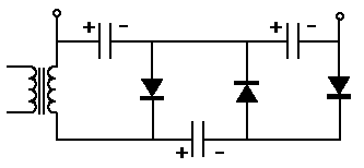
          Here is the voltage doubler I'm using, with some drawn in mods to verify with someone here who knows more than me. Will the mods I drew into this circuit, make a voltage tripler instead of just double..................Or will the whole thing FRY!!

          Please see atached pic below, thanks................................Mike
          Attached Files
          IF IT DOESN'T EXIST, CREATE IT!!!

          Comment


          • Use this circuit:

            You just have to attach a light bulb or a resistor in series of the positive output wire and then connect the other resistor wire and the negatibe output terminal of the tripler to your small capacitor.
            It's better to wear off by working than to rust by doing nothing.

            Comment


            • Originally posted by Jetijs View Post
              Use this circuit:

              You just have to attach a light bulb or a resistor in series of the positive output wire and then connect the other resistor wire and the negatibe output terminal of the tripler to your small capacitor.
              Thanks Jetijs,
              I'm afraid I'm a lame horse when It comes to some diagrams. Could you please draw in the AC input connections, and label the pos and neg DC output like in the pic I posted? The light bulb (resistor) just hooks up in-line in the pos output on it's way to the discharge cap, correct? I test these circuits and play with all this stuff like there's no tomorrow, truth is.....I'm horrified of getting shocked by this stuff. I know if I hook up something wrong, I could fry at these voltages. Just trying to stay safe. Sorry to be a pain, please "bear" with me, I'm still learning. Thanks again...................................Mike
              IF IT DOESN'T EXIST, CREATE IT!!!

              Comment


              • OK,

                Just for confirmation, the top pos and neg on the diagram is output. On the left of the diagram, where the transformer (?) is depicted is AC input. Please tell me if this is correct. Thanks............................Mike
                IF IT DOESN'T EXIST, CREATE IT!!!

                Comment


                • Yes, that is right. The left terminals are the AC input, the upper left terminal the positive DC output and the upper right terminal is the negative DC output. I will make a complete drawing later, of course if you still need one, because you already understood everything
                  It's better to wear off by working than to rust by doing nothing.

                  Comment


                  • Well, that was appearently the correct way to wire it, I got 460VDC from 120VAC input............very cool! I accidentally left the MOT primary hooked up as my resistor (only 1.1ohms resistence), spun the distributor shaft by hand and dang near blew the ends off the spark plugs!!! With a 1.06uF oil cap! Plasma blasted about two inches off the plug ends, I almost wet myself. I really must order a variable resistor, so I can tune this thing in. I even swapped out to a .67uF cap and still was too much for the plugs with the MOT in-line! I put the 100 watt bulb back in and got back under control for now. I think I have ENOUGH voltage for the time being. The extra voltage seems to be showing heat at the diodes now though, I will probably have to go to 4 per plug instead of 2. I'm now going to test a few different bulbs to see what changes with the resistence changes. Later......................Mike
                    IF IT DOESN'T EXIST, CREATE IT!!!

                    Comment


                    • That's great Mike
                      I just tried my generator setup using a voltage doubler for my 230VAC input. That is about 650V on the output. Works fine. I used a 75w light bulb as a resistor. At first I made a test with no vexus circuit attached, no booster side, just an ordinary spark. I made the test for longer time to get more accurate results. The ordinary spark circuit did consume all the fuel in 45m40S. Then I attached the vexus circuit with a voltage doubler. I also attached a microwave diode connecting the ignition coils LV positive to the HV output. And I attached a diode string in series with the ignition coil secondary to prevent the booster cap discharge through the secondary in between the pulses. This is the circuit that I used:


                      Now using the same load and timings, it took 49m14s till the same amount of fuel was consumed. That is about the same percentage (7%-7.5%) of fuel economy as without using the voltage doubler (just about 300V on the booster side). So there you have it. Now we need to think of a way to get water along with the fuel in the engine to see how this performs.
                      Thanks,
                      Jetijs
                      It's better to wear off by working than to rust by doing nothing.

                      Comment


                      • cap type

                        Quick quesiton:
                        What type of capacitors are you using in the Vexus?
                        Electrolytic or something else?

                        Where on-line can I buy them because my local electronics store doesn't stock 400 volt caps.

                        Thanks
                        DonL
                        Don

                        Comment


                        • Hi DonL, I use ordinary electrolytic caps for the voltage doubler/tripler and some pulse caps for the smaller capacity. I bought my pulse caps from ebay. I use these:
                          1uF 400V PETP CAPACITORS. K73-16. Lot of 18 - eBay (item 380072916841 end time Oct-21-08 16:37:27 PDT)

                          I just noticed, that these are 400V caps, I somehow thought that they should be rated for 1000V. And I loaded them with 650V It is good that nothing happened to them. They handled 650V with no problems and no heat
                          Hope this helps.
                          It's better to wear off by working than to rust by doing nothing.

                          Comment


                          • Originally posted by Jetijs View Post
                            Hi DonL, I use ordinary electrolytic caps for the voltage doubler/tripler and some pulse caps for the smaller capacity. I bought my pulse caps from ebay.

                            Hope this helps.
                            Helps a lot.

                            Thank you,
                            DonL
                            Don

                            Comment


                            • That's COOL Jetijs!!

                              We can build on 7% for sure! Thanks for posting your circuit too, I will also be testing a similar animal soon here in the shop. You just gave me a good place to start, thank you.

                              I now have turned my rpm down to 2,100, about average turns for cruising speed. I hooked up another old, oil cap in parallel, 1.06uF + .72uF = 1.78uF. I also just added a Storage cap hooked up on the tripler circuit side of the resistor bulb, that's where it goes right? 15uF 450V (that's real tight running 460V, I know) it's the highest V one I have. Voltage tripler uses three 120uF 450V caps, so, my total available capacitence output is 40uF right? Should be safe to use the a 15uF for storage, I hope. I know I hooked up a 470uF for storage cap one time when I was only using doubler a while back. I guess it tried to pull too much from the doubler circuit and smoked the whole thing, screwed up the caps and the diodes. I'm always frying something. Anyway, back to testing, will be time for another video soon......................................Mike
                              IF IT DOESN'T EXIST, CREATE IT!!!

                              Comment


                              • Mot

                                Originally posted by jstadwater View Post
                                Hey Gibs,

                                Thanks, testing and posting results is the only way we will obtain "perfect circuit" status. I tried inserting a MOT, not sure where it needs to be. These tests w/22uF discharge cap. In-line on the neg. side of the discharge cap to the diodes, kills the plasma event, only regular spark. Same result in the pos side of cap to engine block, no plasma. Those two attempts were with the light bulb still hooked up as a resistor. Inserted MOT in place of resistor (light bulb), notable increase in plasma intensity, still builds heat in the cap and diodes very quickly. Inserted MOT in-line pos side of voltage doubler output to discharge cap, no change noticed. Same for neg. side of doubler output to discharge cap. The only other place I can think to insert it would be before the voltage doubler circuit. Don't think it will change anything, as it didn't inserted in the output side. Let me know if that covers what you had in mind. The more we try, the more we figure out!

                                The 100 watt light bulb measures 10.2 ohms, the MOT primary is 1.1 ohms. I guess that's why the spark intensity increased with the MOT. I still like the lower capacitence level, I think I will triple the voltage now instead of just doubled. Stay tuned for whatever happens next!.......................Mike
                                Hi Mile,

                                Did you measure the resistance on the MOT. It's probably pretty low ... probably lower than the bulb or any resistor that's been used. All that's happening is that the (TOO) low resistance is letting longer term power flow from the supply and/or the starage Cap. The idea with this circuit is to charge the CDI (dump) Cap up only long enough to catch a full charge for your highest required frequency. When the plug fires, the CDI Cap discharges and a minimum amount of wasted power flows from the storage Cap. If you go too low then you will start to melt plugs ... it will just continually arc.

                                I designed VexUs to be customized around this RC relationship, R1 and C1. The addition of an inductor where R1 is (with the proper computed resistance, or resistor in series) can clamp down on the storage Cap current flow thereby increasing the circuit's efficiency and lowering heat everywhere. (insane4evr suggested this)

                                You can 'overdrive' the VexUs circuit to the point where it no longer provides any benefits.

                                I hope this helps and keeps everyone from undue frustrations.

                                Thanks for posting the ladders.

                                Peace,

                                Greg
                                Last edited by gmeast; 10-16-2008, 09:35 PM.

                                Comment

                                Working...
                                X