Just for fun, I did measure the "gap" on a non-resistor plug I had laying around. The shortest distance from the center electrode to the shell or plug base appears to be about 3.5mm. So you are correct. That just seems like a huge gap even with the additional energy and plasma. Normal gaps are around 1-1.5mm. Will the ceramic insulator surrounding the center electrode provide any additional conductivity as a path to the plug base?
Announcement
Collapse
No announcement yet.
Water Sparkplug
Collapse
This topic is closed.
X
X
-
Plug gaps.
Normal plug gaps, when using an old points and condenser equipped distributor system, are typically around 0.9mm, so when upgrading the ignition to HEI(electronic) distributor, the gap can be stepped up to 1.3-1.5mm, as you say, thus when applying the far more serious RPG supplied plasma, you can easily go to the bigger gap without issue.Originally posted by Turbo98 View PostJust for fun, I did measure the "gap" on a non-resistor plug I had laying around. The shortest distance from the center electrode to the shell or plug base appears to be about 3.5mm. So you are correct. That just seems like a huge gap even with the additional energy and plasma. Normal gaps are around 1-1.5mm. Will the ceramic insulator surrounding the center electrode provide any additional conductivity as a path to the plug base?
Note that once you step up a HEI further, to include a CDI driver, as in an MSD or Crane Cams HI6 CDI, you can open the gaps up a little more from the recommended HEI gap too, thus once you add the 4.7UF capacitor supplied plasma from the RPG4700, you can easily open up the gaps to 4-5mm, not a problem. I suggest you keep the gap down to about 3mm though, as plug wear will open the gaps up as the erosion does what it does, so start at 3mm, and then watch both the electrode and plug base for indications of wear. Once you wear them out to about 4mm, change them over for new ones. Simple.
Note the gap size on a Brisk Premium LGS plug, it's factory set at around 3mm, and cannot be adjusted, so if you take all this into account, you'll see that a stripped down plug will happily work in this scenario too. That Brisk plug is designed to run with a simple HEI, and also works great with a CDI spark as well. Just a shame that the electrodes chew out with plasma.
You need to know that spark/plasma always displays a phenomena called "glide effect" or "skin effect" too, where the spark/plasma "glides" over the top of the ceramic, and once you understand this point, you'll be able to appreciate that this phenomena can also be used to your advantage as it allows the spark/plasma to "bend", thus stretching it out further than would normally be the case if you gave the spark an unhindered path to the earth point, like say in a straight line across from the electrode, meaning if the electrode and earth points were directly across from each other, the spark/plasma has no interference.
This "glide effect" becomes apparent if you place a non conductive obstacle directly in the path of the spark/plasma, just like the center electrode ceramic, thus the spark/plasma will have to go around this obstacle to get to the ground/earth points. Take a very close look at the Brisk plug to see how this works, then look at doing the same thing with your stripped down plug.
When choosing a plug to use in the stripped down fashion, select a plug that gives you everything you need right from the outset. Choose wisely.
Calculate your "reach" carefully, and try to get a plug that will allow the electrode/firing point, to be positioned precisely in the middle of the combustion chamber, meaning that under compression(TDC), the electrode is midway between the piston face and the roof of the combustion chamber, but remember, a stripped down plug will be firing backwards at an angle of about 100-120 degrees, so you can place the electrode a little closer to the piston in this scenario, do try to take advantage of this.
It's all about capitalising on the flame kernel, and exposing it to as much fuel/air as possible from the outset.
This firing back angle is best appreciated by looking at how the Brisk plug operates, and the bulbous center electrode ceramic of that plug will give you an idea of how the "glide effect" works, I strongly recommend you study this point and apply your new found knowledge to your best advantage.
Be aware too, most spark plugs were never designed to run plasma, and often the manufacturers join the electrode to the electrode shaft, deep within the plug (where you can't get at it), they do this with a "powder joint", and this "powder joint" will explode if you throw plasma down through it, so again, choose your plug very carefully.
Another thing to watch out for, is the fact that most plugs present a "ceramic hugging" phenomena under pressurised conditions, meaning that when you apply compression, the spark/plasma will not jump across to the earth, even though that appears to be the path of least resistance, rather, under compression, the spark/plasma can, and often does, "hug" the center electrode ceramic, and travels along that to ground/earth deep within the plug base. You'll be shocked to learn that many plugs do this. It's a design flaw, and care needs to be taken to ensure you don't select a plug with this flaw, for if that turns out to be the case, you'll just waste precious time and energy on a set of basically dud plugs.
That ceramic "hugging" phenomena appears to be related to the length at which the electrode protrudes from the center electrode ceramic, and it appears to be more apparent when using a shorter style electrode, so choose a plug that has a nice long electrode.
This is why I suggested that you get your hands on a suitable spark plug pressure tester, for that would then allow you to test a variety of plugs, until you find the one that works for you. If you do opt to go down that path, just ensure you allow fresh air to be passed through the pressure tester, as ionised air exacerbates the problems I've mentioned above, and will give you poor data.
You do learn "stuff" when you start looking into this spark/plasma circus.
Comment
-
Wow. A lot of good points you made for sure. That's what I was talking about--the "skin effect" but I didn't know the term. That's very interesting for sure.
I have thought about obtaining a pressure chamber for firing spark plugs. It would be very interesting to see the difference.
Thanks for all the help understanding plugs and plasma.
Comment
-
Here is a short youtube video that demonstrates what Rosco1 is talking about YouTube - Silver spark plug
Comment
-
"Leader formation and the return stroke"
Ignition CoilsOriginally posted by rosco1 View PostWhile testing plasma via an Aquapulser RPG4700, I noted that the Crane Cams HI6 CDI and PS91 coil supplied spark, did not merge with the plasma, they clearly do remain separate, and this can be seen by anyone who actually takes the time to look for it.
You can physically see the spark tendrils crossing between the ball tip(FireStorm) and the earth cage, as well as seeing the plasma plume, though often they're displaying from a different part of the ball tip, which I assume is related to the ionization effect.
I've shown this to several electrically savvy friends and they're as puzzled as I am about it.
So, if spark of this magnitude does not merge with plasma, meaning they're travelling together all the way from the trigger point(rotor button), along the plug lead to the spark plug, then displaying as being clearly separated at the plug gap, most noticeable when using a FireStorm replication(ball tip), then it's probable that one could somehow make use of the redundant HI6 and PS91 spark for other uses, providing one could devise a way of doing so without interfering with the route of the plasma at the same time.
I'm not sure why they don't merge(I'm not that clever), maybe it's a frequency thing, I don't know, but I'd sure like to know why this occurs, as I would have thought they'd have merged instantly.
That said, I wonder what would happen if one passed the HI6 and PS91 spark into the lead from the opposite direction that the plasma is travelling along?? What would happen then? Maybe nothing, maybe they'll simply ignore each other in the same way they do when travelling in the same direction.
Beats me....
See the 3rd & 4th picture from bottom of the link
Ignition Coils
"Firestorm" Sparkplug, Lightning Analogy?
"Once a channel of ionized air is established between the cloud (the earth cage) and ground (the ball tip) this becomes a path of least resistance and allows for a much greater current to propagate from the Earth back up the leader into the cloud. This is the return stroke and it is the most luminous and noticeable part of the lightning discharge."
Lightning - Wikipedia, the free encyclopedia
Al
Comment
-
Primary as well as secondary ignition source.
Hi Al,Originally posted by aljhoa View PostIgnition Coils
See the 3rd & 4th picture from bottom of the link
Ignition Coils
"Firestorm" Sparkplug, Lightning Analogy?
"Once a channel of ionized air is established between the cloud (the earth cage) and ground (the ball tip) this becomes a path of least resistance and allows for a much greater current to propagate from the Earth back up the leader into the cloud. This is the return stroke and it is the most luminous and noticeable part of the lightning discharge."
Lightning - Wikipedia, the free encyclopedia
Al
I'd be only too happy to subscibe to your answer as being a plausible cause, but it doesn't answer the question as the non merging spark/plasma phenomena I'm talking about is only apparent when the 2x ignition sources are firing simultaneously. The Crane Cams HI6/PS91 is prime, the RPG4700 is secondary.
The RPG requires a spark(provided by HI6/PS91) to effect the dump of its capacitor, thus it cannot function without a prime ignition source, yet when it does engage, it far surpasses the spark of a HI6/PS91, by a long shot.
I do run an on/off switch with the RPG4700, so I can turn it on/off whenever it suits me, and I do use this function a lot when testing.
I can see the HI6/PS91 spark quite clearly, remembering that this is the primary system. When I turn on the RPG, I can still see the HI6/PS91 spark crossing over, as well as the RPG plasma.
Edit: I should add that we have never seen this spark/plasma phenomena when employing the RPG as the primary ignition source, nor have we witnessed it with plasma energy levels all the way up to 100 microfarad.
Comment
-
Sparkplug gap
Hello, guys.
About the gap of the sparkplug, we need to know that its dimensions are NOT set according to the spark energy, but according to the High Voltage delivered by the ignition coil and the electric insulation of the ignition coil (secondary winding), distributor cap and sparkplug wires.
The air is an electric insulator.
In open air, for an electric current to arc between two metal electrodes, we need 1kV for each mm, cause the air has a certain electrical resistance that needs to be broken. And this is in open air.
In the engine the air is compressed, so the electric resistance (insulation) of the air between the two electrodes of the sparkplug is much bigger. That means that you need many KV for every mm of the sparkplug gap. It's not about the energy, but about the high voltage to break the air insulation.
In my country, every ingnition module marketed has to generate at least 7mm spark lenght to be considered reliable. Keep in mind that the average sparkplug gap is 0.6-0.8mm. So, we could assume that each 0.7mm of the sparkplug gap needs at least 7KV to be jumped by the spark. That means a sparkplug gap of 3.5mm needs about 35KV. I think to run with this HV in your ignition system is to wear off the electric insulation of it (ignition coil, distributor gap, sparkplug wires) early... You need to maintain the HV at a minimum to have a long life of the ingnition system. How to do that? It's simple: make the sparkplug gap smaller.
So, the HV determines the lenght of the spark, and the energy of the spark determines it's thickness and, probably, it's duration.
Hope this thoughts help somebody.Real PEACE from the Prince of Peace: Jesus Christ!
Comment
-
HI6/PS91 and RPG4700 Plasma Arcs
Crane Cams HI6/PS91 and RPG4700 different time delays (trigger to ignition resulting from inherent electronic delay) may also explain two plasma arcs.Originally posted by rosco1 View PostHi Al,
The RPG requires a spark(provided by HI6/PS91) to effect the dump of its capacitor, thus it cannot function without a prime ignition source, yet when it does engage, it far surpasses the spark of a HI6/PS91, by a long shot.
I do run an on/off switch with the RPG4700, so I can turn it on/off whenever it suits me, and I do use this function a lot when testing.
I can see the HI6/PS91 spark quite clearly, remembering that this is the primary system. When I turn on the RPG, I can still see the HI6/PS91 spark crossing over, as well as the RPG plasma.
Edit: I should add that we have never seen this spark/plasma phenomena when employing the RPG as the primary ignition source, nor have we witnessed it with plasma energy levels all the way up to 100 microfarad.
Al
Comment
-
Plasma as well as spark.
Hi Al,Originally posted by aljhoa View PostCrane Cams HI6/PS91 and RPG4700 different time delays (trigger to ignition resulting from inherent electronic delay) may also explain two plasma arcs.
Al
Not sure what the difference would be in spark/plasma speeds.
It's not 2 plasmas, it's 1 spark and 1 plasma.
The HI6 delivers 12 sparks per trigger event below 3000rpm, then reverts to a single spark through to the redline. You can't really see the 12 sparks as they're all firing so closely together, rather they appear as a single spark.
That said, if the initial HI6 spark(spark 1 of 12) initiates the plasma dump, which is exactly what happens, then that means that the plasma is travelling through the lead somewhere within the same time frame as the other 11 sparks, you follow?
As I said before, you can still see the long tendrils of spark, crossing between the ball tip and the earth cage, as well as seeing the plasma plume, clearly seperate, and while they sometimes travel close together on the ball tip, making them sometimes hard to distinguish as seperate entities, at other times they appear to jump from widely distant areas of the ball tip, which shows them up much more clearly.
The ionisation effect is very probably the cause of this.
All that aside, the fact remains that they do not merge, as I would have thought to have been the case.
Comment
-
Several ignition coils connected in parallel, using the same coil driver, will produce one-location plasma arc of one-coil HV but at higher output current. Thus Analysis of HI6/PS91 and RPG4700 output invents at two locations requires high-speed video recorder.Originally posted by rosco1 View PostHi Al,
Not sure what the difference would be in spark/plasma speeds.
It's not 2 plasmas, it's 1 spark and 1 plasma.
The HI6 delivers 12 sparks per trigger event below 3000rpm, then reverts to a single spark through to the redline. You can't really see the 12 sparks as they're all firing so closely together, rather they appear as a single spark.
That said, if the initial HI6 spark(spark 1 of 12) initiates the plasma dump, which is exactly what happens, then that means that the plasma is travelling through the lead somewhere within the same time frame as the other 11 sparks, you follow?
As I said before, you can still see the long tendrils of spark, crossing between the ball tip and the earth cage, as well as seeing the plasma plume, clearly seperate, and while they sometimes travel close together on the ball tip, making them sometimes hard to distinguish as seperate entities, at other times they appear to jump from widely distant areas of the ball tip, which shows them up much more clearly.
The ionisation effect is very probably the cause of this.
All that aside, the fact remains that they do not merge, as I would have thought to have been the case.
Al
Comment
-
Active Nitrogen + Atomic Hydrogen = THERMAL EXPLOSIVE ENERGY
I started this thread because of Luc's diode deal. He was looking to replicate
a water fuel circuit.
Here is the answer to the water fuel:
http://www.energeticforum.com/renewa...ater-fuel.html
Active Nitrogen + Atomic Hydrogen = THERMAL EXPLOSIVE ENERGYSincerely,
Aaron Murakami
Books & Videos https://emediapress.com
Conference http://energyscienceconference.com
RPX & MWO http://vril.io
Comment
-
Gas Turbine Jet Engine homemade ignition system - plasma from 1966 inspiration
http://www.technologie-entwicklung.de/Gasturbines/Bangbox/bangbox.html
Bangbox
Ok, I call this thing simply the bangbox, because that is what it does when activated. Producing loud bangs. It actually is a high energy ignition system. And I think it cannot be built much simpler. This is what it looks like, not yet fit with the large storage capacitor, but only 100nF instead.
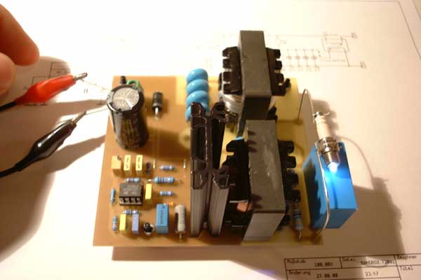
This picture shows the bangbox with a micro spark plug as used on small model aircraft IC engines. The plasma extends approx. 3mm from the gap and is really hot.
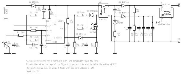
And this is how it works (click on the schematic for a larger version):
A flyback converter transforms the 12V input to approx. 2-3kV (adjustable, depending on energy storage capacitor capabilities) and charges the capacitor. Through a voltage-doubler circuit another (small) capacitor is charged. This cap is connected to an air spark gap, that connects to the primary of a Tesla transformer. When this gap breaks down, the secondary of the Tesla transformer induces about 15kV, which is superimposed over the voltage of the storage capacitor and causes breakdown of the ignition spark plug. Once ionized, the large current, supplied by the storage cap, flows through the Tesla secondary (resistance well below 0.1 Ohm) to the spark plug. A very similar design is used to ignite xenon short arc lamps or argon ion laser tubes.
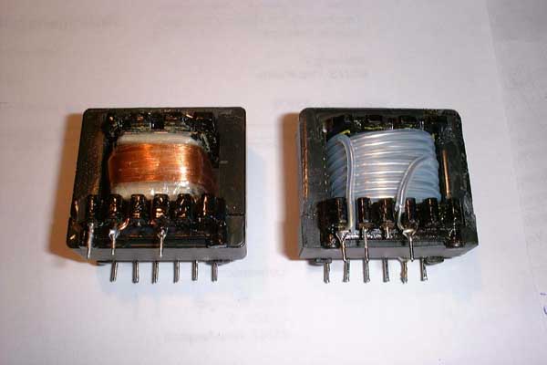
These are the two transformers. The left one is the flyback transformer, primary 10 turns of 2 x 0.5mm dia bifilar, secondary 100 turns of 0.3mm dia, 4 layers with layer isolation. The core has an air-gap of 0.5mm. The right one is the Tesla transformer, secondary 20 turns, 2 1/2 layers, primary 4 turns, no core air-gap. The wire is 1mm dia silver plated copper, threaded into a PTFE tubing with 1.1mm inner dia. Both cores were recycled from power transformators, salvaged from blown desktop PC power supplies. They are approx. 40 x 35 x 12mm3 in size and are of N27 material.
You can download the CAD file for this device here.
The circuit has been designed with Target 2001 by Ingenieurbüro Friedrich. They offer a free demo version of this program at their web page http://www.ibfriedrich.com . The demo is only restricted in component count and should be more than sufficient for this circuit. An English language version is also available, as is the documentation.
To be continued as I get hold of a larger capacitor.
09/25/2000
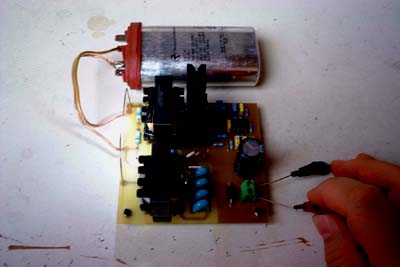
Wow - finally making really big bangs! Last week I obtained a few surplus capacitors for microwave oven - rather cheap. They are rated 1µF at 2100VAC, so they should stand almost 3kV DC. I didn’t want to ruin my small spark plug, so I used two copper wires to form a spark gap. It is about 4mm wide and gets a little bit wider with each bang ;-). It is hard to describe the intensity of the discharges. The repetition rate is about 2Hz, varying slightly. I placed a sheet of paper between the electrodes, just being curious what would happen. The arc rips a hole of about 2mm diameter into the paper, and the flash is still brighter. Next I will try to light a Petromax kerosene lamp with it, because my turbocharger turbine is currently configured to run on propane, but this will be changed one day... So I’ll have to go and get a suitable spark plug capable of a little more power. Taking the above picture was quite difficult because the strong electromagnetic pulse emitted from the bangbox causes my digital camera to trigger itself. After about 30 shots I got the above. But photographing these arcs is somewhat similar to recording the sound of a running turbine - you simply don’t catch the “feeling of it”.
If somebody needs one of these capacitors - I still have some left and will sell them cheap.
Just been experimenting a little bit more with the bangbox: I placed a kleenex, soaked with kerosene, between the electrodes and connected the power. The kerosene lights easily. So I think it should light a turbine combustor as well. Now my ears are ringing - I’ll better put on ear defenders next time.Sincerely,
Aaron Murakami
Books & Videos https://emediapress.com
Conference http://energyscienceconference.com
RPX & MWO http://vril.io
Comment
-
part 2
http://www.technologie-entwicklung.de/Gasturbinen/GTP30-67/body_gtp30-67.html
After another deal with Bruce Linsmeyer from Avon Aero (http://www.avonaero.com) I got an original starter motor (since converting a motorcycle starter seems too much hassle) as well as an ignition exciter and some other smaller components. Yet though I operated the exciter according to the specifications on the type plate, it gave up its ghost after only a few minutes of total sparking time. Seems like I have no luck with these units. Yet Bruce was so kind to send me another one for free, this time everything was ok. The former ones were GLA brand (General Laboratories Assosiates), this one is a Bendix. But since I’m always a little peculiar, I opened the second damaged GLA unit as well. After cleaning out all the rubber resin it was covered with, the photo below was taken.
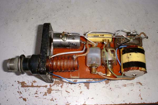
This ignition exciter dates 1966 and is exactly what I had expected. A nice, straight-forward electro-mechanical unit. At the right there’s the voltage converter coil with the trembler points as an integral component above. The points are placed in a hermetically tight cabinet, probably filled with some highly isolative gas (SF6 or the like). The yellow capacitor left from the trembler cabinet is the resonant cap, wired in parallel with the points. Left from the transformer coil sits the gas-filled rectifier diode and then the trigger spark gap. Some of its electrodes’ material had been sputtered onto the glass walls during operation. The series ignition coil is placed in-line with the ignition terinal with the ignition capacitor just above it. All these components are glued to a pertinax plate. On the other site of this plate there’s the large energy storage capacitor placed as well as the two discharge resistors. A more detailed analysis of the failure revealed a partial isolation break-down in the secondary of the voltage converter coil. This will reduce the output voltage to a point where the trigger spark gap won’t break down anymore. Since the other components are still in a pretty good shape and I managed to open the exciter case without damaging it, I decided to rebuild this unit with an electronic voltage converter. After some hours of design work it became amazingly clear how small actually the electromechanical solution of the sixties is. Anyway I managed to construct the electronic exciter circuit in the same place but I can tell you this wasn’t easy. I’ll post a picture as soon as the new version is ready for testing.
And here it is:
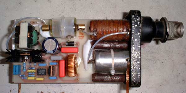
The voltage converter is based on a UC3843 current mode PWM flyback converter chip that allows the construction of a very compact and reliable power supply. Due to the extremely high switching speeds of power MOSFETs, the step-up transformer requires just about 100 turns for the secondary to produce up to 5kV. In this case I used PTFE-isolated PCB patch wire for the secondary because of its superb isolation characteristics.
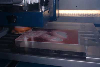
This is a shot of my mill making the PCB (actually nothing much to see).
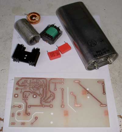
Here some of the components are shown. The PCB is finished. Top right is the big energy storage capacitor, salvaged from the old, damaged ignition exciter. It is rated 1µF at about 5kV.
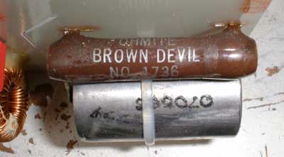
What a nice name for a resistor!
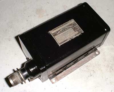
After thorough testing the exciter cabinet finally is soldered hermetically tight and re-painted. As I found out later (read below) good old “Murphy” must have found a way into the cabinet just before I shut it tight...
If anybody is interested in the schematics (very similar to the “Bangbox” but a little simplified and different ignition configuration), please drop me a line.
------------------------------
http://www.gasturbine.pwp.blueyonder.co.uk/page1.htm
Developments to Date
In 1999 my brother built me a high energy ignition system to my good friend Roger Marmion's design. The unit uses a surface discharge plug taken from a racing car engine, light up tests have shown that this arrangement is superior to the high tension systems previously adopted. The ignitor works by using an inverter to charge up a 2uf capacitor, a special trigger circuit provides a low energy spark which ionizes the air and causes a high curent flash-over at the spark plug tip.
Home Built High Energy Ignitor In Action!Sincerely,
Aaron Murakami
Books & Videos https://emediapress.com
Conference http://energyscienceconference.com
RPX & MWO http://vril.io
Comment
-
Solutions...
Aaron,
As you're already aware, normal spark plugs are generally only capable(construction material wise) of surviving up to about .2 or .3 joule.
Anywhere beyond that, and they're just gobbled up fast by the plasma.
You have to first know the plasma energy level required to attain the electrochemical reaction, then design a plug and ignition to suit that requirement.
We've already designed the plug, it's called the "Nascent Plug". It's a duel purpose plug, meaning it acts as the cylinder pre-heater(glow plug) in the start up cycle, as well as acting as the primary ignitor.
We've also designed a duel role ignition system, which is still as yet un-named. The ignition serves to pre-heat the cylinder in the start up cycle, as well as to fire the plug at whatever energy level we choose. This ignition system has interchangeable capacitor capability, enabling us to utilise capacitor sizes from 4.7uF all the way through to 1000uF. It has been tested and has proven itself to be rock solid.
Be aware, the plasma energy level requirement for the electrochemical reaction is within the vaporization zone, meaning it will vaporize diamond, tungsten, and anything else known to mankind.
Now, a normal plug would be lucky to survive for a minute or so at best in that kind of environment.
Specifically designing a plug made out of tungsten still does not meet the requirements mentioned above, for, as stated, the plasma energy level is in the area where tungsten cannot survive either, so while you may get a marginally longer operating life out of running a tungsten plug, it will still fail in short course.
** WARNING to anyone attempting to modify tungsten electrode(off the shelf) plugs, these often contain a powder joint, where the manufacturer joins the electrode to a tungsten tip, and this powder joint is only designed to withstand normal spark energies, not plasma energies, as quoted above(.2 to .3 joule). If you apply a high energy plasma through these types of plugs, they can explode at the powder joint, so please DO NOT attempt this. Safety first!
Our solution to all the inherent problems, was to painstakingly design a plug which "projects" the plasma outward, away from the firing points and plug base, in a controlled "Plasma Jet Plume" effect. Please look closely at the attached image. This is a very advanced plug.
I'm sure you've seen enough plasma to know that it usually always presents itself in a typical "golf ball" shape, thus, you'll also know that this "golf ball" shaped plasma will engulf the plug base, which, at the higher energy levels required, will see that vaporized pretty quickly, along with the roof of the combustion chamber and even the edges of the intake and exhaust valves.
Trying to remove a vaporization damaged plug from a likewise damaged combustion chamber would probably prove difficult, thus we decided to delete the "golf ball" shaped plasma issues and strive for a much more practical, albeit better "modelled" plasma shape.
By doing this, we can safely keep the high energy plasma away from the plug, extending its lifespan to the point where we see no discernable signs of wear, even at plasma energy levels well above those required to attain the electrochemical reaction.
We've tested our plug at (x)uF for 1 hour, in open air tests, with no cooling or anything to assist the plug, and it came out of that most gruelling test with flying colours, indeed, we did not see any significant signs of wear on any part of the plug.
In another test, we ran these plugs for several thousand kilometres in a gasoline engine, with water/methanol augmentation. The trigger was a standard HEI distributor, with a Crane Cams HI6 CDI added, along with a Crane Fireball PS91 ignition coil. Atop that was an Aquapulser RPG4700 radiant plasma generator, and I can assure you, no signs of wear whatsoever are apparent on the plugs when firing at these light plasma energy levels for prolonged periods.
@rmitoday, PM me please.Attached Files
Comment
-
plasma plug
Rosco,
The plug sounds amazing!
The most I used was about 30-40 joules per blast and one single blast
of that on a regular plug shows wear on the little explosion mark.
I can only guess what the plug looks like. There could be geometry that
focuses the plasma I suppose. Nasa and the others always discussed the
Lorentz Force to eject the plasma from the plug since the plasma is repelled
by that magnetic field.
Nasa was using about 150 joules per blast and they had geometry in the
plug so that the Lorentz Force ejected torus rings of plasma into the
combustion chamber.
Anyway, very interesting and can't wait to see them!
Pretty wild how all these things came together.Sincerely,
Aaron Murakami
Books & Videos https://emediapress.com
Conference http://energyscienceconference.com
RPX & MWO http://vril.io
Comment
Comment