Announcement

Collapse
No announcement yet.

Water Sparkplug

Collapse
This topic is closed.
X
X
 
  • Filter
  • Time
  • Show
Clear All
new posts

  • #61
    I watched the video rick. Where are the plans?

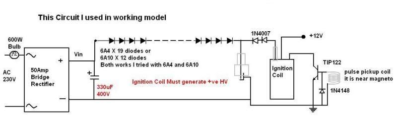
    I figured out why my diode exploded and added a relay contact to disconnect charging. Push button to charge, release to fire. May need to add a set of contacts to isolate the ground from the bridge if I understood Aarons description.

    Hell ya baby, whip out the plans, I'll take a stab at at. (probably) I will definately be going with an electric starter. :-)

    Comment


    • #62

      Comment


      • #63
        Originally posted by rick123 View Post
        Have you attempted the Diodes in Parallel?

        This is straight from Chemelec, which has a WHOLE LOT of Credibility!

        "Some Persons believe two diodes in parallel Doubles the Current Rating. However just putting two diodes in parallel may or may not increase the current rating at all.

        All diodes have a foreward voltage drop and if you measure a bunch of a particular diode, (even all being in the same batch) you will find each is slightly different at a given current. And this can change in a Non-Linear way for other currents.

        When diodes are placed in parallel, the diode with the Lowest Voltage drop will
        conduct the most Current.

        This could result in No Advantage, Partial advantage or High Advantage.
        But Extremely Doubtful it will ever Double the current.

        One way to help fix this is to put a Low Value, Series Resistor in front of Each Diode.
        The voltage drop across this series resistor tends to Equil Out the differences in the diodes. The resistance of each series resistor should provide a voltage drop, somewhere around 0.3 to 0.6 volts at the current draw of the particular circuit it is used in.

        Another Problem that can occur sometimes: Is when a large filter capacitor is used after the diode and If the Power transfomer has a low impedance and is capable of driving large currents. "This Inital High Surge Current, Can Damage the Diodes".

        In these cases it is advisable to place a low value, series resistor. Sometimes it is called a "Fusing Resistor". This resistor Raises the Effective Impedance and Lowers the High In-Rush Current to a safer level, thus protecting the diode from damage.

        In Low Voltage Supplies, Resistor Values between 0.1 ohm to 10 ohms are quite effective. And in High Voltage Supplies, Values between 47 ohm to 100 ohms are used to fix this. In the case of a Diode Bridge Circuit, a resistor is placed on Both Inputs.

        A bit of Wisdom, from my many years experience."

        Attached Files
        RedMeanie
        (psst...Don't Tell Anyone, But I'm Really Not Mean!)

        Comment


        • #64
          I decided to replicate Ossies circuit.
          This is the original one:


          At first I decided to make the upper circuit part, that would make the sparks across the spark gap at variable frequency, like this:


          This worked fine, here is a video:
          YouTube - another test

          Then I made the lower part of the circuit with a 75w light bulb. I used a capacitor from a disposable photo camera, there are no readings on the cap, so I can't tell you the capacity. At first I just powered up the bottom part of the circuit. It was not attached to the upper part. I just wanted to see if the cap would charge up and it did. As the cap charged up, the light bulb went on for a short time. So I attached the bottom circuit part to the upper part as in the circuit diagram. At first I turned on the inverter, and then the switch that turned on the upper part, but nothing happened. I could hear the transistor switching, but there were no sparks. I turned the inverter off, but still no sparks. Only if I remove one of the bottom circuit wires from the spark gap, the sparks appear. What could be the problem? Any suggestions?
          Thanks,
          Jetijs
          It's better to wear off by working than to rust by doing nothing.

          Comment


          • #65
            That's a good demo. Best so far of the arc staying lit. Nice work.

            Just out of interest is there any theoretical efficiency gained by using this method compared to electrolysis and piping hydrogen directly to the combustion chamber as Daniel Dingel does now?

            YouTube - Water Car ... Daniel Dingel

            Also the general process is exactly the method which Stanley Meyer was using as described on wikipedia.

            "He replaced the spark plugs with "injectors" to spray a fine mist of water into the engine cylinders, which he claimed were subjected to an electrical resonance. The fuel cell would split the water mist into hydrogen and oxygen gas, which would then be combusted back into water vapor in a conventional internal combustion engine to produce net energy."

            Except that they misunderstood the concept. It's obvious now that he didn't use the spark plugs to create the spray for injecting. He used the spray as the method to get the hydrogen excited so it could be easily split by the arc that the plugs provided when lit.

            In the end though it's just igniting hydrogen.

            Makes me wonder why for so many years so much money has been invested into Fuel cells and supposedly delayed due to not being able to create enough hydrogen for the mass market at efficient prices. Doh, all they needed was a car battery and they could star the ball rolling.

            I'm thinking that hydrogen would make a good modification for my gas oven. What is the likelihood of blowing myself up if the gas was left on for a couple of minutes like with lpg? Would the hydrogen dissipate quickly and be less of a hazard?

            Finally I have noticed that there is a lot of momentum on Hydrogen as a fuel in the past month from many different parts of the world. Seems that critical mass has been reached now and it may not be long for this idea to become common knowledge. Keep up the good work exploring the possibilities.

            Comment


            • #66
              Gotgas:
              I read your post #34 about 4 times. Very insightful for me, thanks for taking the time to write it. I am finally starting to understand the principle. I had to read the thread several times. The capacitor size does not matter, it just matters that there is a compactor because of its characteristics. The characteristics of the inductor (ignition coil) also matter. Now I can start seeing the circuit for what it truly is.

              I built the capacitor70's circuit and I keep blowing the transistor? I will have to do some more reading. I wrote the guy who made that cold fusion plasma 9 video. Maybe he will reply. Rick
              Last edited by rick123; 07-08-2008, 03:24 AM.

              Comment


              • #67
                Compressed spark checks vs. humidity

                I love this subject, it is utterly cool and my deepest respect goes to all who are building and studying it!!

                When you consider the possibilities and permutations of testing the spark performance under pressure conditions (which is certainly important work), it would seem to get deceptively complex.... For instance, because the water content of the air has been proven by Luc to be a factor you would have to decide what relative humidity air to use Compressing humid air of a certain relative humidity should increase the actual humidity level inside the chamber verses "1 atmosphere"... Which could certainly account for differing spark observations.

                Test open-air with 60% humidity, then take an air supply of 10% humidity and compress to 6 atmospheres? Dunno for sure if that works lineally, tho. Yikes. Scratch that one lol.

                Or simply compress differing humidity air and compare the sparks. Still doesn't tell you what effects/changes are simply from compression and not humidity :/

                So maybe some sort of base line would first be needed on how the spark reacts at different relative humidities at 1 atmosphere. So just how to accurately and repeatably do that? Judging by color alone may be perfectly good for someone working alone, but difficult to relate subtle differences to fellow experimenters. Photography light meters? Dunno. The ones i've seen react rather slowly. And there is the infra-red content. Gotta be a better way...

                ...Unless you lived or tested in the desert, or anywhere humidity is very low anyway, and then compression would not significantly raise it. Then the humidity issue could be discounted and it gets a whole lot simpler.

                Comment


                • #68
                  Applying pressure to the spark

                  Originally posted by jibbguy View Post
                  I love this subject, it is utterly cool and my deepest respect goes to all who are building and studying it!!

                  When you consider the possibilities and permutations of testing the spark performance under pressure conditions (which is certainly important work), it would seem to get deceptively complex.... For instance, because the water content of the air has been proven by Luc to be a factor you would have to decide what relative humidity air to use Compressing humid air of a certain relative humidity should increase the actual humidity level inside the chamber verses "1 atmosphere"... Which could certainly account for differing spark observations.

                  Test open-air with 60% humidity, then take an air supply of 10% humidity and compress to 6 atmospheres? Dunno for sure if that works lineally, tho. Yikes. Scratch that one lol.

                  Or simply compress differing humidity air and compare the sparks. Still doesn't tell you what effects/changes are simply from compression and not humidity :/

                  So maybe some sort of base line would first be needed on how the spark reacts at different relative humidities at 1 atmosphere. So just how to accurately and repeatably do that? Judging by color alone may be perfectly good for someone working alone, but difficult to relate subtle differences to fellow experimenters. Photography light meters? Dunno. The ones i've seen react rather slowly. And there is the infra-red content. Gotta be a better way...

                  ...Unless you lived or tested in the desert, or anywhere humidity is very low anyway, and then compression would not significantly raise it. Then the humidity issue could be discounted and it gets a whole lot simpler.

                  The reason I posted those results was to show that a spark amplifies under pressure, and that white plasma can be obtained without going to the trouble of using inverters etc.

                  By going the high voltage route, I expect we will see a fast expiration of the spark plug components. Indeed, why have such a powerful spark in open air, when pressure in a combustion chamber will take care of the amplification for us.

                  I reason that as we already know a blue spark won't ignite water vapour, what if we amplify that blue spark with a simple inline capacitor to achieve the desired white stage, then see if it will do it's thing to water vapour under pressures above (for arguments sake) 75-100psi.

                  I feel that HHO is very much the key here, and there should later be a percentage of HHO mixed in with the water vapour, I reason that the HHO will aid the combustion of the water vapour and will assist the compressed white spark in getting a decent ignition event happening. It would be a 2 stage approach.

                  My test bell window is already leaking, and while I intend to repair the leak, I'm also considering the fitting of a simple blow off valve(say 120psi) to the side of the bell head, (it does allow for that), and I may inject a water vapour at the white spark under pressure to see what happens.

                  I'll have to think this through as I don't want anything bad to occur. I can already see the pressure cell window making like a bullet if I get this right, or wrong??? Depends on which way you look at it I suppose.

                  Comment


                  • #69
                    If you look at nearly all the water fuel patents, they all fired multiple times. Most people think that the step charge was something that took place in the cell, that is not true and if you look at the circuit it is simple to see.

                    Another place people get confused is they are not sure if they are looking at a electrolyzer or an injector which I am sure is by design. Meyer's methods covered all of them from pulse compression US 4936961 seen here and is why the pulse train doubles, to what appears to be a plasma water resistor setup seen here in US 4798661

                    or even just his New Zealand video where he admits he patented up all the processes and did so with authorization of an executive order from Regan.

                    I really think it is time for people to break out of attempting to replicate and to begin to try new things, your own new things and if you ever hit pay dirt, remember the frustration we all feel and don't sell out or be the next Stanley, put it out there. You will never benefit any more than EVERYONE if history is our guide.

                    Siemens is a large corporation and they make piezo injectors that produce a pressure greater than 10,000 feet below the surface of the ocean for the new European emission standards. Therein may be your injector / fine mist solution. Siemens also has done extensive research in electrolysis and offers for sale transformers "rich in current harmonics". They are the size of a truck. Google "siemens electrolysis" if you get bored.

                    The Bohr model of the atom states that when a mass loses energy, it absorbs light. Voltage is light and in GB they refer to the electrostatic force of the atom as the color force if I am not mistaken. Meyer used a 120 PSI water pump. When water goes from 120 PSI to ambient instantly, it almost or does boil for a moment.

                    So I really feel it is important to follow your intuition. We have enough people doing monkey see monkey do Dave cells and other useless distractions although there is something to be learned from all of it.

                    I am going in the mag amp direction and current rich harmonics which is what Boyce was up to I suspect. The reason is all the water cars have a power source the size of a welding box. In fact, Meyer's looks like one that was painted over on his dune buggy. The Japan car from a few weeks ago, same thing. Dingle's power supply appears to be that size and the part of the core you can see looks to be the size of my 70 amp welder. Current is magnetic, voltage is not.

                    Here is a shot of the underside of Dingel's hood and the japan water car power supply. Both scream magnetic current and current rich harmonics to me.
                    Attached Files
                    Last edited by GotGas; 07-08-2008, 06:32 AM.

                    Comment


                    • #70
                      Originally posted by rosco1 View Post
                      By going the high voltage route, I expect we will see a fast expiration of the spark plug components. Indeed, why have such a powerful spark in open air, when pressure in a combustion chamber will take care of the amplification for us.
                      Did you mean to say "By going the high amperage route"? Since voltage isn't going to hurt anything, amperage is what we use to weld with.

                      I can touch my finger to a million volts and it won't hurt me or anything else except a CMOS chip perhaps. On the other hand, 300ma of current is usually what they use to start/stop your heart at the hospital.

                      Thanks for posting those results by the way - it was interesting. I suppose the higher the air pressure, the more conductive it gets since there are more ions available. You could probably use the law of squares and atmospheres to calculate exactly what what would be with a given air sample.
                      Last edited by GotGas; 07-08-2008, 07:22 AM.

                      Comment


                      • #71
                        Originally posted by Redmeanie View Post
                        Kinda like this setup...
                        I didn't think to use the neon. Do you still maintain a good plasma? My diode exploded and hit me in the face. I added a relay contact to disconnect the power during firing. DA!

                        This circuit operates way different than what I originally thought. What a goofy idea, mixing a high voltage and high current line together like this. Who'd of thunk it?

                        Is there some science that suggests something different is going on here or is this a way to compensate for not having the right plasma source / transformer?

                        Comment


                        • #72
                          Tomorrow, if all works out well, I will get an old Russian car in fairly good condition. It has no computers, no sensors, no nothing. It has a spark distributor, that can be turned in any timing position you need. I always wanted a test car for my booster, joecell, ect. experiments. So you will have to help me to get this thing to run on water.
                          It's better to wear off by working than to rust by doing nothing.

                          Comment


                          • #73
                            Imortant new information

                            Hello folks,

                            I was just over at the waterfuel1978 group site, and noticed that a new message and file had been posted by s1r9a9m9. As files seem to be disappearing at that site, about as quickly as they are posted, I immediately copied the file and posted it in the Public folder of my Windows Sky Drive.
                            I think that should be okay since waterfuel1978 is an open public forum, and I gave full credit to s1r9a9m9 as being the document author. I will show a link to the file between the dotted lines below, but first an explanation is in order.

                            When Gotoluc posted his s1r9a9m9 replication videos on YouTube, s1r9a9m9 watched the videos and made the following comment, "Nice set up. If you use a coil with two windings going through a main coil to boost the output spark up about 10 times what you have now, you will have a system almost like mine."

                            Today, sir9a9m9 posted a new message concerning this coil, along with a document explaining it further. He also said that he would be posting a video soon, showing how the coil is actually wound. Hopefully he will also share some additional details.
                            ----------------------------------------------------------------------

                            Here is a link to the transformer file:
                            S1r9a9m9 transformer coil.rtf - Windows Live SkyDrive

                            UPDATE - S1r9a9m9 has now also posted a photo showing the silver cup that appeared in his YouTube video of the 18 hp engine running on water, and also shows what was inside the cup. You will see this photo, and a close-up of the photo, plus a new pdf file in which s1r9a9m9 explains the step-up transformer coil that was in the silver cup. See them here:
                            S1r step up transformer coil.jpg - Windows Live SkyDrive
                            ----------------------------------------------------------------------
                            Note that s1r9a9m9 says the inverter isn't needed, and that in fact it can not even be used with the transformer setup. It looks like s1r is finally going to show us the missing pieces (or at least some of them), and that is great.

                            I hope this information spurs some additional experimentation and modification of the circuitry. I have been watching this thread with interest, and you have all been making excellent contributions to the effort. Keep up the great work!

                            Rickoff
                            Last edited by rickoff; 07-09-2008, 02:55 AM. Reason: UPDATE
                            "Seek wisdom by keeping an open mind to alternative realities, questioning authority, and searching for truth. Only then, when you see or hear something that has 'the ring of truth' to it, will it be as if a veil has been lifted, and suddenly you will begin to hear and see far more clearly than ever before." - Rickoff

                            Comment


                            • #74
                              Thanks Rick!
                              As for me, I finally figured out what the problem with my setup was. The high voltage from my induction coil was negative, that means that I needed to reverse the polarity of the bottom circuit part. Got some nice and powerful sparks, but the run battery went down. I will charge it up and then make a video. Also, all the sparking keeps disturbing nearby electronics - computers and radio, also my signal generator is affected in some way, sometimes it just restarts to the basic settings. I will have to leave some space between the signal generator and the spark gap.
                              Thanks.
                              It's better to wear off by working than to rust by doing nothing.

                              Comment


                              • #75
                                Well, I killed my inverter
                                I wanted everything to be simple, so I used a bridge rectifier after the light bulb instead of the diode array. Like this:


                                The cap charged up and and the spark was very powerful. I set my function generator so that it fired the transistor about 2 times per second. And then, after about 10 powerful sparks, the inverter died. I should have used those diode arrays, maybe it would protect my inverter. After this I opened the inverter and saw that there are two 30A fuses burned out. But I don't think that replacing those fuses everything will work again.
                                It's better to wear off by working than to rust by doing nothing.

                                Comment

                                Working...
                                X