Announcement

Collapse
No announcement yet.

Water Sparkplug

Collapse
This topic is closed.
X
X
 
  • Filter
  • Time
  • Show
Clear All
new posts

  • Hi everyone.
    I've checked the schematic I've posted last time (CDI-plasma ignition), and I saw that there is a mistake made.
    The pin4 of the first 555chip (U1) must be wired to +.
    All the best.
    Real PEACE from the Prince of Peace: Jesus Christ!

    Comment


    • Aaron,
      The taking of pictures and posting them is a bit outside of my technical capabilities - will have to seek some assistance on that score!

      Nothing too complicated in grinding off the earth electrode - the washer needs to be positioned with a tapered centering mandrel to ensure equal gap around the centre electrode whilst brazing.

      I suspect a continual arcing/discharge may be required for best operation - the duration to match the exit time of the water mist from the plug cavity. I will be trying several modes of operation - one using the "MSD - 6A" (multiple spark CDI unit).

      Will post on my findings - may be a while though - lots of projects on the go.

      Just found an entry by s1r on the Yahoo Waterfuel1978 forum - a link to a company -"Perma Tune" manufacturers of high performance igniters (including plasma) for automotive applications - claiming suitability for ALL petroleum fuels - even diesel in a petrol type engine configuration.

      Industrial Ignitors from Perma Tune
      Last edited by neva.; 08-29-2008, 09:26 AM.

      Comment


      • Originally posted by gotoluc View Post
        Hi neva. and aboard

        Interesting information you are sharing there. Thanks...

        ...it is possible as Frederic Gauthier (a French Canadian like me who lives a few hours from me)
        Luc
        Hi Luc, I'm French Canadian too!

        I wonder if we're not so far away from each other.
        I live on north shore of Montreal. If you wish to say, where are you from?

        Peace.

        Comment


        • Voltage Doubler

          @ Aaron,

          Sorry to hear about the censorship issues.

          I would like to enhance the circuit (yours) with a 1/2 wave voltage doubler (X-Box's). I don't think my relay can handle a direct feed, so I am wondering, if I run a separate supply from the variac to the doubler then to the Caps on the backside, would that work? I would double the number of diodes as a precaution.
          As always, your input is welcome.

          Rgds.
          D.

          Comment


          • Induction or not induction?

            Hello Radiant-1 and All,

            I have thought long and hard about your post. It would not be fair or correct to dismiss your observations because I don’t share all of your views. So I focused on the following statement.

            Originally posted by Radiant-1 View Post
            ....So, in an ignition coil, we run off of the backspike of energy (which was provided by magnetic collapse "induced"...not our circuit energy)...
            I don’t share your view here. I believe that the capacitor is the sole source of energy and induction does not play a part in the generation of the HV spark in this circuit. I do agree however, that the coil, any coil, will produce a reversal in all cases and therefore can not produce pure DC. Inductive discharge would account for the enhanced spark but without the diodes in the circuit there is a normal HV spark.

            IMO this is a very fundamental argument and to progress our understanding of the effect we need to start with a firm grasp of how the ignition coil in our circuit operates. I and many others have formed opinions and theories based on observation and experimentation. In my case, I have realised that my observations and theory was based on two assumptions.

            The first was based on the internal construction of the coil. I assumed the primary winding is wound over the secondary winding in the same direction and that internally, both windings share a common connection on the negative side. The second was that the normal inductive cycle was omitted and replaced by the capacitive discharge.

            It has become clear to me that these two assumptions could invalidate my own understanding as my observations were based on these assumptions. I set about observing the circuit with my scope to at least prove or disprove that induction is not taking place. I have studied the waveform directly from the primary winding and indirectly from the coil as a whole by wrapping 15-18 turns of 24#SWG ECW around the casing.

            All the waveforms I have studied so far have shown a high voltage spike at the moment of the capacitor discharge. The primary winding in particular, showed the 250v spike of the capacitive discharge followed by a much longer tapering 10v polarity reversal terminated by a ringing wave.

            Currently, I’m not able to prove or disprove induction isn’t taking place. One fact does remain regarding my mental picture of the connection and relationship of the primary and secondary coils if the ignition coil. If the HV spark is the result of a inductive collapse of the primary, the HV spark would be the opposite polarity of a capacitor discharge and vica versa.

            I have more questions than answers at the moment. The experiments continue.

            Regards Lee…

            Comment


            • Originally posted by Gibs View Post
              Hi Luc, I'm French Canadian too!

              I wonder if we're not so far away from each other.
              I live on north shore of Montreal. If you wish to say, where are you from?

              Peace.
              Bonjour Gibs,

              I'm a 1.75 hour drive from you. In our National Capital city of Ottawa. Frederic Gauthier was also from Montreal (when I contacted him)

              Luc

              Comment


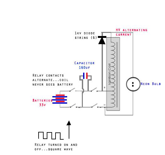
              • Below is info which was sent to me from Radiant-1 who unexpectedly (sic!) was banned from this forum for disrespecting an Admin. I hope you will accept description of his experiment which IMHO is important.

                In regards to Spark Plug operation modality.

                Ok...here it goes...if you do this, and post it, just acknowledge my work a little...plz

                Well, I figure that a differential in spark gap length (while enough for me to figure it out) isn't quite definitive enough for others.
                So, I took the liberty to devise an experimental check.

                For the experimental check this is what I did.

                1. A 555 timer triggers a 12v single pole relay, that triggers a 24v dual pole relay that charges a 160uf capacitor with 33v supplied by the three 12v batteries in series (not fully charged), and dumps it into the ignition coil primary.

                2. Across the HV to LV negative I placed a neon bulb. This neon upon operation w/o diodes, had both terminals glowing, so AC...Furthermore, one was slightly dimmer then the other (forward induced wave vs. Flyback wave)...Flyback being the brighter.

                3. Now, I attached the diode string...Only the brighter (now even brighter) terminal is now lit.

                This proves that the forward induced (out of phase) wave of the secondary is temporarily conducted back to LV positive(as this wave happens first) this sets up a feed back loop...then when the flyback induced wave occurs the diodes stop conducting, and the energy of the feedback loop is slammed into, overcome, then added to the higher potential wave (now slightly lower voltage due to wave destruction...but carries more amperage).

                My method of operation is now almost %100 confirmed...THIS IS how the Gray tube worked as well, so, Aaron is right about that connection.


                Last edited by boguslaw; 08-29-2008, 06:12 PM. Reason: Correction

                Comment


                • Inductive operation

                  Originally posted by boguslaw View Post
                  Below is info which was sent to me from Radiant-1 who unexpectedly (sic!) was banned from this forum for disrespecting an Admin. I hope you will accept description of his experiment which IMHO is important.
                  Thanks for this boguslaw,
                  The schematic is helpful. I haven't evaporated a neon for quite some time I have been looking hard into this yesterday and today. I will try to get some scope shots together over the weekend.

                  Regards Lee...

                  Comment


                  • Well,I imagine other but related to Radiant-1 discovery experiment, but unfortunately I cannot perform it due to many reasons. You may however find it interesting.
                    It's nothing more just testing if such modified circuit has still the so called "back EMF". Normally when you power ignition coil it will produce HV on secondary and quite a few hundreds volts on primary during magnetic field collapse. To test it is used commonly a diode like 1N4007 connected across low voltage negative and positive of car coil along with a neon which is lighting by back EMF (similar method is used in Imhotep radiant oscillator to charge battery while powering CFL)

                    What I suspect is , that it may be no back EMF when sparkplug effect occurs.

                    Could it be ?


                    (radiant-1, I modified your schematic for showing my idea .I hope this is OK for you ?)
                    Attached Files

                    Comment


                    • 10x BY448 gives wonderful spark - not on plug but on anode

                      Hi all,

                      something must be wrong with my choice of diodes. I used this one:

                      http://www.reichelt.de/?;ACTION=7;LA...4ecc90c2621a0e
                      BY448 1500V case S

                      Just in the moment I connect 10x BY448 in series with capacitor, parallel to spark plug gap, the spark on plug disappears, no matter if cathode to HV plug positive and anode to cap positive, or cathode to cap positve and anode to plug. When cutting connection capacitor/first of 10 diodes (10 diodes keep connecting on spark plug positve), spark appears right here at cutting point. After the distance is increased (>~3mm) the spark comes back on plug. No matter forward or backward of the diodes.

                      Must be wrong diodes. I tried even 20 in series of them. Same missing spark on plug, but spark at cap-diode-connection, when opening connection. After distance is larger than ~3mm, spark comes back on plug.


                      What type of diode(s) are you suggesting?

                      Who has long duration experience with diodes? One single HV type? Which of them keeps staying cool?
                      How are 1N5404 performing? Do they get hot or stay cool?
                      Better 1N5408?
                      Someone has diodes already killed due to heating up?


                      Hi Radiant 1,

                      sorry for getting stress with Aaron.
                      I tried to understand your writings, but my english is not good enough to.

                      What is the difference between condenser parallel to spark gap and diode?


                      magnetO

                      Comment


                      • Bemf

                        Originally posted by boguslaw View Post
                        Well,I imagine other but related to Radiant-1 discovery experiment, but unfortunately I cannot perform it due to many reasons. You may however find it interesting.
                        It's nothing more just testing if such modified circuit has still the so called "back EMF". Normally when you power ignition coil it will produce HV on secondary and quite a few hundreds volts on primary during magnetic field collapse. To test it is used commonly a diode like 1N4007 connected across low voltage negative and positive of car coil along with a neon which is lighting by back EMF (similar method is used in Imhotep radiant oscillator to charge battery while powering CFL)

                        What I suspect is , that it may be no back EMF when sparkplug effect occurs.

                        Could it be ?


                        (radiant-1, I modified your schematic for showing my idea .I hope this is OK for you ?)
                        Hello boguslaw, radiant-1 and All,

                        I have tried Radiant-1’s schematic on my circuit. Sadly, I was unable to observe as the neon was so bright I couldn’t see the electrodes clearly. There was also an effect on my circuit with intermittent sparking, even at reduced frequencies. I connected the neon directly across the primary winding and the negative side electrode lit, which is what I would expect.

                        I included the diode in the circuit as boguslaw had suggested. The neon did not light. This is unsurprising as my scope measured the BEMF in the primary at 5 – 10 volts, this is no where near enough to light a neon. However, with a larger capacitor the output from the BEMF across a diode will charge a battery as long as the output voltage of the BEMF is grater than the charge battery voltage.

                        There are a few important differences with my set up. My storage capacitor is only 4uF and it is charged to around 200v for these tests. As my videos show, I have no problem producing the effect with such little input energy but due to the limited energy stored on my capacitor I may be unable to produce the more intense effects.

                        After today’s testing I am certain that the HT spark is the result of direct capacitor discharge through the primary winding and not the inductive collapse of the “charged” primary winding. However, I’m not certain of the interactions there after, so I’m unable to agree or disagree with any other theory put forward. I do intend to share my experimental data for all to discuss and review, it will just take a bit of time.

                        Regards Lee…

                        Comment


                        • It is really interesting.I can only say that when long time ago I tested car ignition coil, powered commonly from square wave generator I had to shunt BEMF because it was far above 100V . I used neon across low voltage terminals of coil.Neon was lit in dull orange.

                          Thank you Lee

                          Comment


                          • Hi everyone.
                            magnetO, I could not say that I have a lot of knowledge using the diodes string, but here is what I can say:

                            - diodes overheat due to overcurrent. E.g: appliyng 400V on a 10 Ohm circuit that includes a diode rated at 30A max (pulsed) will result in "cooked" diode, cause the current raises to 40A... The warming is calculated with this formula:
                            Q=I x I x R x T
                            "I" depends on the voltage applied
                            "R" is the resistance of the circuit (depends on number of the diodes string in our case)
                            "T" depends on the value of the capacitor used to discharge; the bigger the cap, the longer the time to discharge, and the warmer the diodes...

                            - diodes are reverse surge stabbed (I don't know the exact term) due to overvoltage. This happened to me when I used a too large spark gap (15mm) with a string of 15 diodes 1N4007 (rated at 1000V). A few times the spark occured, but then they ceased. The voltage was just a little bit above their max limit...
                            After that, I made a string of new diodes (20 x 1N4007), used 12mm spark gap, and they work fine till now.
                            Remember that the spark needs 1KV to jump every 1mm of air gap.

                            BY448 are rated at 1500Vmax, so they are better than 1N4007, and have a bigger current too. But they are also much more expensive...
                            Anyway, BY448 is a good choice to make, but must be careful about the number of diodes in string. You should put diodes so that the maximum voltage raise value to be under the max voltage of the string.
                            E.g: if you work with max 15Kv, use at least 13-15 diodes BY448 (the string would have 19.5-22.5KV max voltage, and there will be 1.15-1.0KV on each diode). Let's hope they will do.

                            All the best.
                            Last edited by Kinetix; 09-01-2008, 06:38 AM.
                            Real PEACE from the Prince of Peace: Jesus Christ!

                            Comment


                            • Water spark motorcycle

                              Originally posted by revizal View Post
                              All,
                              I've just tried what Tero used on his Lawnmower several times ago. It seems real simpler to switch plasma ignition thru original magneto engine's ignition system without relay, SCR, or reed switch. Yes, we could not adjust timming ignition (mean:retard it) but in my experience it hard to adjust timing engine with reed+relay. This engine runs smooth with more power. Just like Aaron's lawnmower, my genset runs even on fully closed throttle valve position.

                              Any suggestion if this circuit I runs on motorcycle without modification on original ignition system ?

                              [ATTACH]1057[/ATTACH]

                              And this is the video:
                              YouTube - Engine Running On Plasma Ignition-2 (Gasoline)

                              Thanks,
                              Rev.
                              I just post 2 videos on youtube.com about my last expectation on running motorcycle by using water plasma spark.

                              YouTube - Plasma S1R-Tero's on Motorcylce
                              YouTube - Motorcyle Running on Plasma Ignition

                              Thank you for all posting in this thread that make it worked.
                              Regard,

                              Rev

                              Comment


                              • Originally posted by revizal View Post
                                I just post 2 videos on youtube.com about my last expectation on running motorcycle by using water plasma spark.

                                YouTube - Plasma S1R-Tero's on Motorcylce
                                YouTube - Motorcyle Running on Plasma Ignition

                                Thank you for all posting in this thread that make it worked.
                                Regard,

                                Rev
                                Hi revizal,

                                great job Have you noticed anything different like less smoke coming from the exhaust?

                                does it run smoother?

                                will you try mixing some Diesel in the gas at a small ratio first and increase to see how high a ratio you can go?

                                Thanks for the video's and sharing.

                                Luc

                                Comment

                                Working...
                                X