If this is your first visit, be sure to
check out the FAQ by clicking the
link above. You may have to register
before you can post: click the register link above to proceed. To start viewing messages,
select the forum that you want to visit from the selection below.
I have been thinking hard on this one Further study of scope traces have provided me with a better insight into what the effect actually is. I was wrong about the reduced resistance, it’s actually far more simple than that.
My scope shows that my secondary coil rises to spark 20uS after the SCR conducts. During this time my capacitor drops from 200v to 180v. Before the voltage on the secondary winding gets high enough to arc across the gap there is only one path for the energy stored on the capacitor to get to ground, through the primary winding.
The addition of the diode in the circuit does a very simple thing. Once the arc has formed, the energy stored in the capacitor has a new path to ground via the HV diode and the arc. There is so little resistance in this new circuit path that it is as good as a dead short across the capacitor terminals. CRACK A disruptive capacitor discharge straight to ground.
The poor ignition coil has had 20v (200v to 180v) dropped across the primary winding in barely 20uS. There is just enough voltage on the secondary to arc across the gap and CRACK… No more energy in the capacitor to deliver to the primary winding and drive the voltage up in the secondary to maintain the arc. The ignition coil has had the rug well and truly pulled from under its feet. Being a coil with a sudden loss of current, the magnetic field collapses. There was so little energy stored in the magnetic field of the coil at the time the capacitor shorted its energy across the gap that the BEMF is insignificant.
There are a few significant points here. The diode/s are important because they have to hold back a reverse voltage as the secondary rises into the KV range before there is enough voltage to create the arc. Once the arc appears it is like shorting a 200v capacitor out with a diode, anode to positive cathode the negative. Increasing the voltage on the capacitor to over 300volts, assuming the cap can handle it, will not stress the ignition coil with the HV diodes in place. It may, however, increase plug ware no end.
With increased voltage on the capacitor you will have a very violent discharge across the arc. Due to the fact that the capacitor shorts across the arc as soon as it is formed the duration of the spark event is very short, much shorter than a standard HT spark.
I have wondered where all the apparent energy came from. When I drove the ignition coil inductively via a 555 timer and transistors, that circuit used almost 4 Amps and everything got hot. My batteries got battered by that circuit and I was plagued with transistor failures.
My current circuit does what it does on 1 amp@ 12v. I have managed to squeeze a frequency of 48Hz out of my charge pump, charging the cap to 200v. Although the charge pump transistor does get warm, nothing else does and other than initial 7555 failures, I have not lost a component on this circuit after many hours of testing.
This "water spark plug" is the most basic and straight forward manifestation of Puriarch's patent #4394230, which was the slightly redrawn and patented again by Stanley Meyer's (his water plug). I have taken the liberty to add in a little piece I was "given"...(Let me first state that I have been up for over 24hrs now...on absolutely no drugs , something has compelled me to make this compilation and share it).
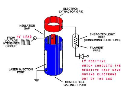
I now understand the importance of "splitting the positive...and let me share it with all you...this Water spark plug is bigger then many of you may imagine!
First, let me start with Puriarch...This is an illustration of his patent, which I have taken the time to highlight for your enrichment, the EXACT same specifics of this here experiment!!! Only, with a different inner electrode WATER!!!
On the left, the original...on the right my notes...
Now Meyer's
I hope that it clicks for everyone else now!!! We have all the parts now, lets uncover this and send it to all!! And, GOODNIGHT zzZZZ
Hi all,
I think this is an interesting concept as the water, being the central electrode, is already at HV potential and may assist with ionisation. It could also be used as a sacrifical electrode.
After watching the plasma fusion video, it seems they are more concerned with high current (600 Mega Amps).
Some people have observed an object resembling a largish transformer in the more successful watercars.
I was thinking of experimenting with a handyman arc welder (capable of around 130A at 2V) with water being pumped through a small tube/nozzle as an electrode.
Of course a HV pulse would be needed to initiate the spark, but perhaps having the welder set up and switched on with no spark, then applying a HV pulse ,would the
welder current follow?
I think everyone is on the right track with the waterplug as people are realising that to produce enough HHO only with electrolysis is very difficult.
It would be more a combination of technologies.Perhaps the electrolysis produces a small but vital role in aiding combustion?
Any comments, criticisms gratefully accepted.
I have been thinking hard on this one Further study of scope traces have provided me with a better insight into what the effect actually is. I was wrong about the reduced resistance, it’s actually far more simple than that.
My scope shows that my secondary coil rises to spark 20uS after the SCR conducts. During this time my capacitor drops from 200v to 180v. Before the voltage on the secondary winding gets high enough to arc across the gap there is only one path for the energy stored on the capacitor to get to ground, through the primary winding.
The addition of the diode in the circuit does a very simple thing. Once the arc has formed, the energy stored in the capacitor has a new path to ground via the HV diode and the arc. There is so little resistance in this new circuit path that it is as good as a dead short across the capacitor terminals. CRACK A disruptive capacitor discharge straight to ground.
The poor ignition coil has had 20v (200v to 180v) dropped across the primary winding in barely 20uS. There is just enough voltage on the secondary to arc across the gap and CRACK… No more energy in the capacitor to deliver to the primary winding and drive the voltage up in the secondary to maintain the arc. The ignition coil has had the rug well and truly pulled from under its feet. Being a coil with a sudden loss of current, the magnetic field collapses. There was so little energy stored in the magnetic field of the coil at the time the capacitor shorted its energy across the gap that the BEMF is insignificant.
There are a few significant points here. The diode/s are important because they have to hold back a reverse voltage as the secondary rises into the KV range before there is enough voltage to create the arc. Once the arc appears it is like shorting a 200v capacitor out with a diode, anode to positive cathode the negative. Increasing the voltage on the capacitor to over 300volts, assuming the cap can handle it, will not stress the ignition coil with the HV diodes in place. It may, however, increase plug ware no end.
With increased voltage on the capacitor you will have a very violent discharge across the arc. Due to the fact that the capacitor shorts across the arc as soon as it is formed the duration of the spark event is very short, much shorter than a standard HT spark.
I have wondered where all the apparent energy came from. When I drove the ignition coil inductively via a 555 timer and transistors, that circuit used almost 4 Amps and everything got hot. My batteries got battered by that circuit and I was plagued with transistor failures.
My current circuit does what it does on 1 amp@ 12v. I have managed to squeeze a frequency of 48Hz out of my charge pump, charging the cap to 200v. Although the charge pump transistor does get warm, nothing else does and other than initial 7555 failures, I have not lost a component on this circuit after many hours of testing.
All The best Lee…
Once again Lee, you really put your in this one and it shows. Most excellent explanation to which most everyone will easily understand.
I will post your circuit effect explanation on the Overunity topic.
I don't understand what you mean about 1 amp @ 12 volts. Your circuit appears to produce 200+ volts on the output of the bridge? I thought your discharge was about 80 millijoules by my calc. I am running 3.385 joules and it's just barely enough to get a good water explosion. 5 joules is much better with a very loud pop and pressure. It also appears as though dumping 412 volts @ 3300uF (280 joules) changes the color of the discharge from white to blue. Once this happens water explodes very violently and with much more pressure. I have not tried your SCR based design under these conditions but I will soon.
Hydroz:
It's my opinion after working for 15 years on standard and high voltage electrolysis that they are both dead ends in terms of viability of daily use in vehicles, generators, etc. This water explosion technology is really the only game in town when it comes to driving pistons efficiently and solely on water.
Everyone:
Color of the discharge appears to give indication of power level and also how easy larger volumes of water explode (may seem trivial to some), but changing from white to blue discharge color and shows a whole new level of ability to explode water. The color of a blue discharge will change to white when water is added however. The diode string appears to be an important variable when trying to achieve maximum effect for a given power level. 1 joule appears to be the extreme low end of this effect. Also, input is limited by capacitive reactance on the AC line on my circuit. This gives very good current limiting and inrush current control without trying to make a bunch of power resistors smoke . Use the Wiseman design for this use, it's well worth it as it also increases voltage while controlling current. Total circuit resistance has been found to have a major effect on discharge intensity as well. Tiny jumper wires etc on my circuit and I lose a large portion of the effect.
I don't understand what you mean about 1 amp @ 12 volts. Your circuit appears to produce 200+ volts on the output of the bridge? I thought your discharge was about 80 millijoules by my calc. I am running 3.385 joules and it's just barely enough to get a good water explosion. 5 joules is much better with a very loud pop and pressure. It also appears as though dumping 412 volts @ 3300uF (280 joules) changes the color of the discharge from white to blue. Once this happens water explodes very violently and with much more pressure. I have not tried your SCR based design under these conditions but I will soon.
Hello Fester and All
The input source for my circuit is a 12v 5Ah gel cell. When the circuit is running the average current is 1 amp measured with a moving coil ammeter. The battery runs the logic circuit and the charge pump which is just a 240/12v step down mains transformer. The secondary 12v winding is switched by a transistor driven by an oscillator at a fixed frequency(which I can’t remember off hand). The FWBR is connected to the 240v primary winding which steps up the pulses from the 12v secondary winding, rectifies and collects them in the 4uF capacitor.
In my latest batch of tests my cap was charging to 200v in 17mS, this takes around 30 pulses from the charge pump. The time between sparks was 20mS (50Hz). If I reduce the spark frequency to 25Hz, via the logic circuits oscillator, I can get 320v or so into the cap in 34mS.
I very much prefer the higher spark frequencies when working with the scope, 100Hz would be far better but as I have said, the limit to frequency in my circuit is the charge pump and how long it takes to charge the cap. I could use an inverter but I only have a small 150watt and it’s used regularly in other experiments.
Color of the discharge appears to give indication of power level and also how easy larger volumes of water explode (may seem trivial to some), but changing from white to blue discharge color and shows a whole new level of ability to explode water. The color of a blue discharge will change to white when water is added however. The diode string appears to be an important variable when trying to achieve maximum effect for a given power level. 1 joule appears to be the extreme low end of this effect. Also, input is limited by capacitive reactance on the AC line on my circuit. This gives very good current limiting and inrush current control without trying to make a bunch of power resistors smoke . Use the Wiseman design for this use, it's well worth it as it also increases voltage while controlling current. Total circuit resistance has been found to have a major effect on discharge intensity as well. Tiny jumper wires etc on my circuit and I lose a large portion of the effect.
Hi UncleFester, thank you for sharing your findings of when the spark gets to the blue light point. Is this the point when you can no longer look at the spark without your eyes hurting?
Have you experimented with higher voltage vs. higher capacitance?
I have found (in open air) that higher voltage and less uf capacitors give better effect than low voltage higher uf capacitor. Video demo: YouTube - Capacitance Vs. Voltage and Diode Test 1
Did you notice this also?
Have you done the spark tests under pressure (with viewing glass) to see if the spark changes?
Thanks. 200 volts sounds more like it for the discharge side of the circuit
Gotoluc:
Yes, the voltage made a huge difference in my setup as well. I went from 200 to 412 volts and found a major improvement. This one coil (MSD Blaster 3) is run from a high powered MSD driver which puts out 450 volts. Same with the Crane and Mallory drivers that are rated for close to one joule maximum. At 412 volts I can go with a multitude of different caps and yet once a threshold has been reached you can no longer get any more power to the plug. For instance if I go from 25uF @ 412 volts to 700uF @ 412 volts I don't see the improvement expected. The jump in power is staggering and yet the output just doesn't show it. Now the jump from 2uF @ 412 to 25uF @ 412 volts is major effect wise.
We are testing all kinds of plasma conditions. We have a chamber which puts two plugs side by side and we can put compressed air, nitrogen, Co2, or Argon into the chamber up to 150 PSI. With nitrogen at 25PSI + the effect is again increased all the way up to 150 psi. The discharge also changes color under these conditions as well.
Hallo everybody. smw1998a & UncleFester, you have given very interesting and useful information. Thank you! UncleFester, have you tried side-gapped spark plugs in your setup? Have you noticed any diferrence exploding the water with various ground electrode shapes?
All the best.
Real PEACE from the Prince of Peace: Jesus Christ!
We've tried all kinds of different configurations of plug. Since we are testing the Firestorm plug we also test along side it with normal plugs, and modified plugs with no resistor and the ground electrode removed. The Firestorm makes plasma the easiest of all and at lower energy levels.
I have now configured my Water Spark Plug circuit to trigger off of the line sine wave. That means that the circuit is operating at 60 Hz. It was only after I got it running this fast was I able to connect the characteristic "SNAP" or "CRACK" with the oscilloscope trace. I will post a video that will show the signature wave form appearing and disappearing in synchronization with the characteristic sound as the circuit misses an occasional beat.
But first I will show you the O-Scope traces. You have already seen them if you viewed my last video. The attachments below are the scope captures that appeared in the video. The Cap discharge trace with the 'crook' in it was thought to be the trace where the HV diode is merely included in the circuit (which it is), and the 'smoother' trace is without the HV diode (which it is). But further, however, the trace with the crook in it IS the signature of the effect ... or more clearly ... the CROOK itself IS the signature of the effect.
This is all very exciting! I will compile the video as quickly as I can so you all can see that the effect actually has a 'face'.
We've tried all kinds of different configurations of plug. Since we are testing the Firestorm plug we also test along side it with normal plugs, and modified plugs with no resistor and the ground electrode removed. The Firestorm makes plasma the easiest of all and at lower energy levels.
Thanks for this UncleFester, I haven't the luxury of testing high powered electronics, my plugs are tested straight into the car. So far I can definitely say that my firestorm replication using resistorless plugs out perform everything else. They also look totally different when pulled - almost like a blued effect and total clean, I can wipe a white cloth over the cage and they are clean, no soot - nothing! And I am running them in a motor that is 300plus Klm's old! I would really love to get the sort of power that you guys are talking about, into my running vehicle with FS plugs in place.
Inspired of Ozicell video, I posted a video on youtube to get the real effect on plasma ignition system. We can show the original ignition spark and compare to plasma ignition. Still by using 47 uF 250 volt with power AC supplied 220 V (0.45 A). The 2nd spark plug connected in seri to the original spark plug. In this setup we could view the real spark effect. Now, I'm sure this setup runs on high frequency based on engine's RPM. Capacitor could not fully charged at high frequency. I though small capacitant in high voltage capacitor is better for such application.
Comment