Announcement

Collapse
No announcement yet.

Stanley Meyer Explained

Collapse
This topic is closed.
X
X
 
  • Filter
  • Time
  • Show
Clear All
new posts

  • @HMS-776

    You are right - this was what i was talking about in my description of EM fields in the WFC - the principle is the same, the only differance is the conditions for the result.

    Thanks for a good post!

    - Behold the truth -

    Comment


    • Sorry about that, not trying to cause probs...

      Just trying to share with everyone what I have learned. Like you said there's more than one way of doing this. My goal is to build everything as close to Meyer as possible to understand the work, whereas you can understand it better by doing it your own way. Both will work. We just have different ways of thinking.

      So back to the Driving Circuits. I will explain this from the beginning so hopefully everyone can have a better understanding.


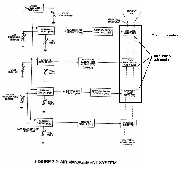
      Lets start from the beginning. The above diagram comes directly from Stan Meyers Tech Brief page 3-28. It is the block diagram for the ECU.

      THE LASER ACCELERATOR

      On the top you see the Laser accelerator. The laser accelerator is an optical distributor which uses light to cause a pulsed output.

      Examples:

      Optically triggered electronic ... - Google Patent Search

      Hydrogen Powered Commodore

      (See fig 3)

      The pulsed output created by the optical distributor goes to a chip which converts frequency to voltage, and as the frequency varies, so does the voltage. This voltage signal, as shown in the diagram splits 4 ways and goes to circuits which are called summing circuits.

      The Air Pressure Sensor, RPM monitor, and Engine Temperature sensor also create a variable voltage signal which goes to a summing circuit.

      The summing circuits are basically that, summing circuits, the output voltage is the sum of the input voltage(s). Summing circuits are made using OP Amp chips like the LM741, for example.

      Each summing circuit has it's own trim pot at it's output, which is used as a voltage divider. This makes engine adjustments as simple as adjusting a knob.

      As Stan states in his patent # 5,293,857

      Paragraph 6

      "Idling, low temperature operation adjustments or other calibration adjustments for normal or ambient conditions are made by trim pots..."
      If you know something about electronics you can see how this is going together, how simple it is, it's all analog (variable DC voltage), which in itself is extremly simple.

      Many people probably thought Stan was a genious, but in fact during the
      70s, 80s, and early 90s most cars had analog voltage systems. Meyers merely studied and copied them. Nothing new, nothing hard!

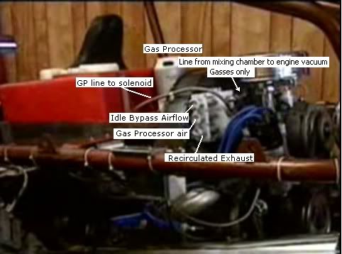
      The output voltage from the summing circuits is applied to FET's. The applied continusously variable voltage controls the amount of current which flows through the differential solenoids thus controlling the flow of the gas(es) flowing through them and into the mixing chamber, which then enters the engine through a vacuum line.


      The line going to the air cleaner is actutallt the Idle Air bypass line. THe mixing chamber line is under the throttle plate.

      Stan had three differential solenoid control valves mounted on a panel.One was for the exhaust recirculation,the second was for the processed air,and the third one went to the air cleaner.The air cleaner air would have been used for the idle air control like all EFI cars use today.It would control the idle speed.No water was put through any of these valves.
      All of theses valves are pictured in the memo for the injector system,423 I think. -Dynodon
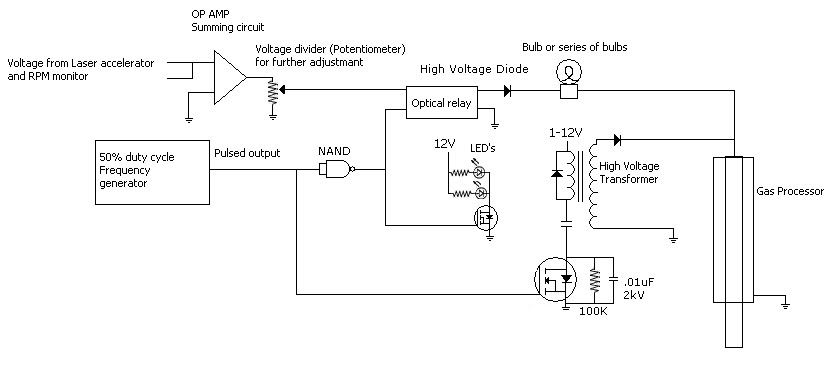
      The summing circuit which controls the Gas Processor solenoid also controls the EEC. The analog voltage from the summing circuit is also the voltage applied to the EEC. Some changes can be made, Personally I would add a voltage divider (pot) to further adjust the applied EEC voltage and start at the lowest voltage possible. When dealing with the amount of energy possible, you should always start low and work your way up.

      Keep in mind Coloumbs law, as Stan taked about in his NZ vid and the EEC circuit. If you apply 1 volt you'll get 1 amp of current flow....Use the proper bulbs, and start at a low voltage!


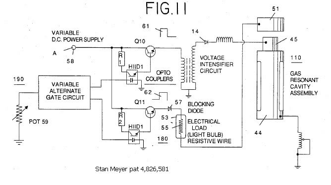
      Here's a quick circuit I just whipped up. Of course all the Resistors and things aren't there, but those parts are simple and any electronics forum or book can help you there. I'm just trying to give an example for now. Also you'll notice that the drawing closely resembles Meyer's in his patent # 4,836,581. Figure 11 in that patent is pretty good. If the Ground is an isolated ground simple connect the negative to the GP negative electrode.


      In the diagram above you should notice 2 things, First that the applied Volatge to the EEC is a low voltage. And Second that the frequency generator has a pot, meaning it is a VCO (voltage controlled Oscillator).

      Now one thing people may not understand, is how the EEC makes a complete circuit. And the way it does is the chamber in the Gas Processor has an area containing an excess number of free electrons (ionized from the Oxygen atoms), it is the free electrons that form the negative (ground) and complete the circuit. It is what I call, an invisible ground.

      Back to the Laser Distributor, if you studied the example I gave an understand how it works, you should understand that the Laser distributor can also be used to control Injector timing, which I believ Stan did. The pulses can be used to turn on and off the injectors to each cylinder very easily. These types of distributors allready exist. One thing you want to keep in mind though, is that the injector duty cycle needs to be able to change as well, which creates the need for using the throttle, RPM, and Air Pressure sensor.

      The VIC as I have stated many times is meant to produce a continuous voltage. The voltage is applied to the conventional part of the distributor which applies it to the injectors.

      It's hard to just describe one part of the system which needs the entire system to function. If you want to control the GP, you've got to make it work with the entire system at various engine loads, RPM, and temperatures! And being that every system is different I cannot explain it all.

      Some great References for more understanding. They are expensive so I just check them out at the library.

      Understanding Automotive Electronics is a great book, with several editions. The earlier editions are more based on Analog circuits which is what we need to understand here. There are also many books on electronics and analog circuits!

      If you build the Gas Processor, you do so at your own risk! You must understand the energy available with such a reaction!

      Hope everyone Enjoyed the post!
      Last edited by HMS-776; 08-29-2009, 08:59 PM.

      Comment


      • Thanks HMS-776,

        For you are very correct in that there is more than one way to do this, that is why I wont knock anyones designs. Here I just wanted to focuse on the water fuel injection system, but the gas injection system will also work. It has more parts than the water injection system and is of Meyer earlyer design. Perhaps someone should start a thread for Stanley Meyer's Gas Injections system for not all cars will be able to accept the water injection system easily. I would like it if you would start a thread on the Gaseous injection system, that way I can come to your thread and help as much as I can on that front too. Both of us have a good working knowlegde of how Stanley Meyer did what he did so I think it would be a great idea, what do you think?

        For I found this great site for hydrogen systems that would take a lot of the work out of creating a gaseous injection system here: Alternative Fuel CNG Engine Conversion LPG Hydrogen Erdgas Now in these systems you will have to make the WFC as the source of the fuel for the injectors as well as the quenching tubes to take the combustable gas to the injectors or fuel rail. But it is very possible and most of the control systems have already been made for such a system. So basically all one would need is the WFC set up to maintain a given pressure to opperate the system, and the same means to control the gas processor as can be found here or adapted to fit their system.

        The main reason for a new thread is this one is for the water injection system only for the most part. And as I have just shown you the Gaseous injection system has help from the site I posted. They sell Gaseous Hydrogen injectors and the means to control them with cpu's already made. On that system now would be easyer for not a lot would have to be made and the circuits might be adaptable to the WFC and Gas Processor. Just thinking out loud here, for I think you have something that we can all follow to energy independence, yet another way, or do you want me to start it? Anyway it is best not to put the two different systems in one thread as it will more than likely confuse people.


        h2opower.

        Comment


        • Hi Everyone,

          This is to let everyone know that I have put, sebosfato, tutanka, and Oneminde on the ignor list and sujest everyone else do the same for if you do not it will read funny as I will not be responding to them on this thread.

          sebosfato and tutanka have far too different ideas for this thread to handle and Oneminde is a instigator one that tries as start fights when he see's different thoughts come out. The reason I tell everyone this is people have a right to know why I did what I did. For if I didn't the thread would never move forwards the way I intended it to move, thus Stanley Meyer's technology would never come out. Again the goal of this thread is to replicate Stanley Meyer's injection system and also come to a full understanding of the science behind the invention. I hope everyone understands the decisions made here.


          h2opower.

          Comment


          • I guess it seems like I am talking about the gaseuos system, but I am not. I am only working on Meyers End product, anything else would be a waste of time.

            In Meyers End product, there are 2 systems. The Gas System and the water system. This has been confirmed after talking with Dynodon, who has seen the car personally several times. I have even asked him to look for certain things for me for clarification which he has done helped a great deal.

            In Meyers end product, the only thing that flows through the injectors is the heated water. The Recirculated exhaust, Ioinized air, and ambient air are all part of the gaseous system which enter the engine using engine vacuum.

            Comment


            • Originally posted by h20power View Post
              Hi Everyone,

              This is to let everyone know that I have put, sebosfato, tutanka, and Oneminde on the ignor list and sujest everyone else do the same for if you do not it will read funny as I will not be responding to them on this thread.

              sebosfato and tutanka have far too different ideas for this thread to handle and Oneminde is a instigator one that tries as start fights when he see's different thoughts come out. The reason I tell everyone this is people have a right to know why I did what I did. For if I didn't the thread would never move forwards the way I intended it to move, thus Stanley Meyer's technology would never come out. Again the goal of this thread is to replicate Stanley Meyer's injection system and also come to a full understanding of the science behind the invention. I hope everyone understands the decisions made here.


              h2opower.
              Dear H2OPOWER,
              You can ignore me , oneminde or sebosfato but you can't ignore that peoples have an mind. If you write this is clear that you are confused at this time.. not good idea answer these words.. At this time you don't hav anyting that work only more words and nothing else.H2opower you don't are an genious you copy only an genious..

              Comment


              • Now the reason for heated water was already made clear as it has to do with the phase diagram of water. This is the science behind the technology.

                Before the injectors the water is under pressure in Meyer's system 125 psi so over 100 degree C water will not boil before the injectors, but after the injector the pressure in the intake system is below atm typically -15 psi. So water injected into that vacuum pressure will imedeately turn into vapor at the same tempreture. This aids the voltage zones in that the water coming into them is already at a very small size, think of it as a head start to the charge and divid process of breaking water down as show here:


                Again this is the science behind the technology so everyone has a clear understanding as to how it all works. Hot water at high pressure injected into a low pressure zone into a high pulsating voltage zone. The water is also undergoing evaperation which aids the process for the surface charge density will be shrinking allowing voltage to perform work on the water molecules. As long as the water droplets are in the voltage zone they will the process will keep going. Any hydrogen and oxygen gas created in the voltage zone is subject to being striped of electrons prior to entering the combustion chamber. I hope this makes it very clear how the water fuel injectors work and why the water is being heated prior to injecting it into the voltage zones of the injectors.


                h2opower.

                Comment


                • Originally posted by h20power View Post
                  Now the reason for heated water was already made clear as it has to do with the phase diagram of water. This is the science behind the technology.

                  Before the injectors the water is under pressure in Meyer's system 125 psi so over 100 degree C water will not boil before the injectors, but after the injector the pressure in the intake system is below atm typically -15 psi. So water injected into that vacuum pressure will imedeately turn into vapor at the same tempreture. This aids the voltage zones in that the water coming into them is already at a very small size, think of it as a head start to the charge and divid process of breaking water down.

                  Again this is the science behind the technology so everyone has a clear understanding as to how it all works. Hot water at high pressure injected into a low pressure zone into a high pulsating voltage zone. The water is also undergoing evaperation which aids the process for the surface charge density will be shrinking allowing voltage to perform work on the water molecules. As long as the water droplets are in the voltage zone they will the process will keep going. Any hydrogen and oxygen gas created in the voltage zone is subject to being striped of electrons prior to entering the combustion chamber. I hope this makes it very clear how the water fuel injectors work and why the water is being heated prior to injecting it into the voltage zones of the injectors.


                  h2opower.
                  HI everyone,
                  Is clear that Meyer is illuminated for creation of injector from Peter Graneau experiments on longitudinal force in water.. Is mentioned on Electrodynamic Explosions in water that: Superheated steam has been suggested to drive a thermal explosion. Is an case?? I think not... you can read with your eyes here: Experiments
                  Last edited by tutanka; 08-29-2009, 10:16 PM.

                  Comment


                  • H2OPOWER,

                    I hope my explanation of the circuits above helped. They really are simple circuits. The problem is I have limited skills when designing and building them. I understand the basics of how they work but as far as building them I have not had much practice at it. That is why i cannot give any definite schematic and guarantee it will work. For now I can only show concepts of how the circuits could work. Hopefully that will change in the coming months!!!

                    It's hard to get things right the first time, and I don't want to be wasting people's time building circuits that do not work or are not reliable.

                    Once I feel I have the correct knowledge and am capable of building simple, reliable circuits I will gladly post them, everything included. Right now I just feel like I would be causing alot of troubleshooting work, and problems as my circuits design knowledge is not complete.
                    Last edited by HMS-776; 08-29-2009, 11:38 PM.

                    Comment


                    • Yes they helped HMS-776,
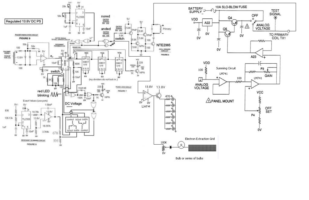
                      If you would can you draw the EEC and the LED driver on the nored side of the part where it says 'Switch' on the 4001 close to the primary coil and make it so the EEC and the LED driver has it's own FET? Thanks. And also add in figure 4 having the 'to primary coil TX1' hooked up to the spot where the 'IRFP450' is, for 'J' is where we would hook the engine control and management systems to in figure 4. For Q4 and Q5 are a Darlington transistor: Darlington transistor - Wikipedia, the free encyclopedia and that should be the correct way to hook everything up.


                      We must work together for we are getting help from a lot of good like minded people, thanks HMS-776.


                      h2opower.
                      Last edited by h20power; 08-30-2009, 12:39 AM.

                      Comment


                      • Why didn't you show it h2o?... if you know everything?
                        Is that the reason why do you want to create an ignorance list????????????
                        For those who don't ignore science http://www.energeticforum.com/renewa...eyer-true.html
                        Attached Files
                        Last edited by sebosfato; 08-30-2009, 05:16 AM.

                        Comment


                        • This is as good as I can do for now....I would recommend posting the Voltage Amplitude control circuit on the forums at allaboutcircuits.com, let them know the voltages your working with and the current flow through your primary and they will get you squared away pretty quick.

                          As far as that PLL circuit, a few people have claimed that it works. You can read the posts on the first testing of this circuit below, which I would highly recommed so you can have a better understanding and build it correctly:

                          The Water Fuel Cell :: View topic - Phase lock loop circuit schematic

                          The Water Fuel Cell :: View topic - Stans international circuit examination

                          Read the posts above and you will find some people with good knowledge on this circuit that will explain it much better than I could. Best of luck!

                          Comment


                          • Thanks so much HMS-776,
                            As always I will keep you posted of any test I will run on the water for fuel program for there is safty in numbers.


                            h2opower.

                            Comment


                            • circuit notification "ground"

                              Originally posted by HMS-776 View Post
                              Sorry about that, not trying to cause probs...

                              ...


                              Here's a quick circuit I just whipped up. Of course all the Resistors and things aren't there, but those parts are simple and any electronics forum or book can help you there. I'm just trying to give an example for now. Also you'll notice that the drawing closely resembles Meyer's in his patent # 4,836,581. Figure 11 in that patent is pretty good. If the Ground is an isolated ground simple connect the negative to the GP negative electrode.
                              ...
                              Hope everyone Enjoyed the post!

                              ...

                              Hi Hms-776,

                              for general notation clarification I want to suggest to use the term "ground" only when it means system overall ground (i.e. ICE metal case or grounded to earth).

                              So there is no more "isolated ground" - letīs call it 0V or zero level.

                              greetings,
                              bussi04

                              Comment


                              • Exactly which grounds need to be isolated again? They can't all be isolated, can they? I notice in the schematic HMS drew up for H2OPOWER, all the grounds are labeled 0v. Which need to be isolated?

                                Comment

                                Working...
                                X